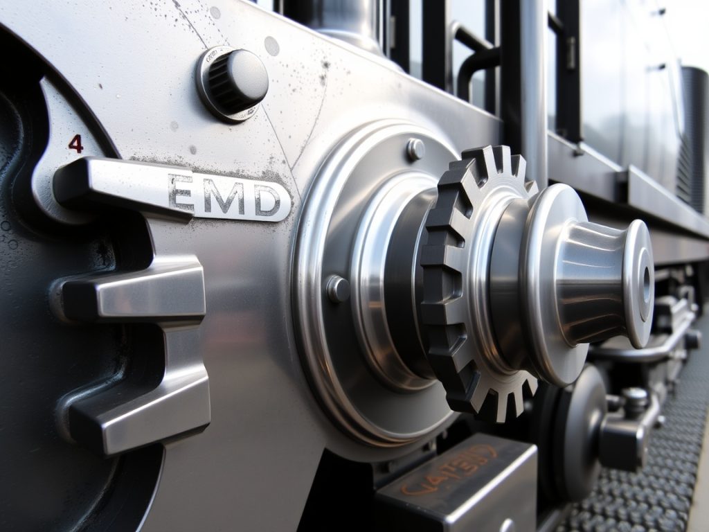
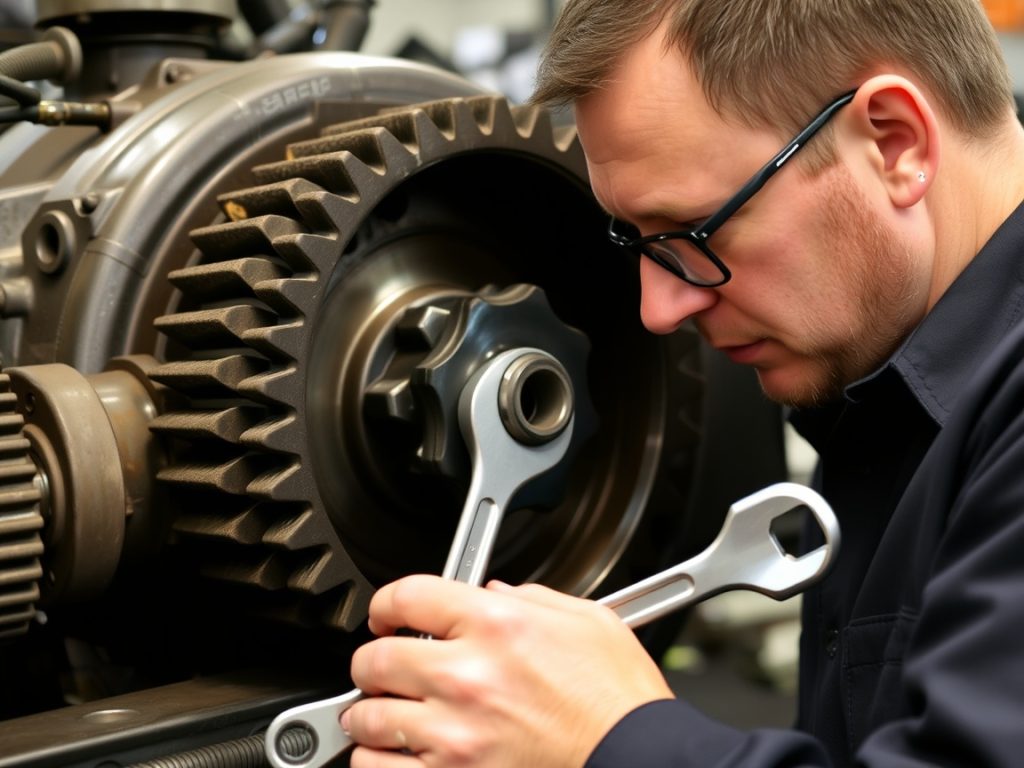
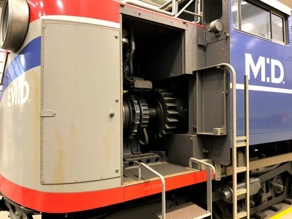
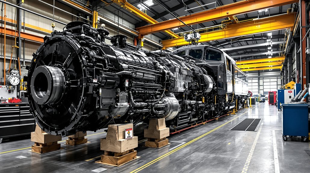
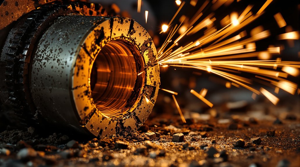
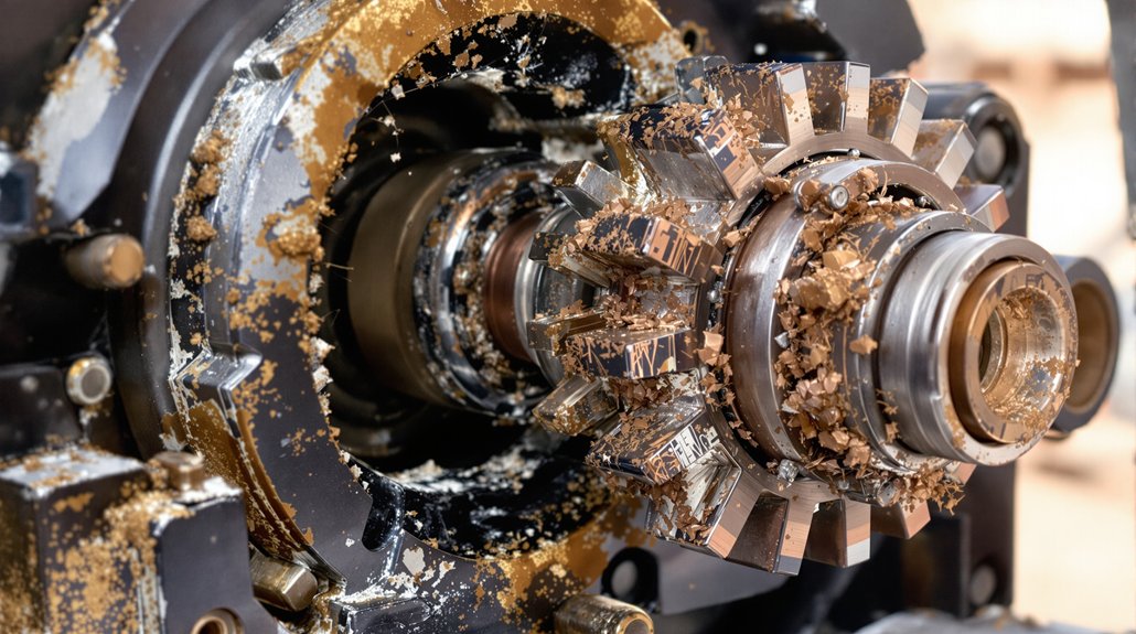
How to Fix Bearing Lubrication Problems in EMD Locomotives

How to Fix Bearing Lubrication Problems in EMD Locomotives

You’ll fix bearing lubrication problems in EMD locomotives by first diagnosing scavenging pump inefficiencies through pressure monitoring and prelube time comparisons between engines. Select proper babbitt-based alloys with steel backing for main bearings and aluminum-tin combinations for connecting rods, ensuring lead-based overlays meet 0.015–0.030″ thickness specifications. Maintain oil quality using micron-rated filters and conduct analysis every 500-1,000 hours. Activate auxiliary pumps 35 minutes before startup and verify all pre-lube parameters. Advanced diagnostic tools and predictive maintenance protocols will enhance your troubleshooting capabilities considerably.

Key Takeaways

  • Diagnose scavenging pump inefficiency by monitoring extended prelube times, pressure fluctuations, and comparing performance between engines.
  • Install proper bearing materials using babbitt-based alloys for main bearings and aluminum-tin combinations for connecting rods.
  • Maintain oil quality through micron-rated filtration, regular oil analysis every 500-1,000 hours, and sealed reservoir contamination prevention.
  • Activate auxiliary motor-driven pumps 35 minutes before operation and verify pre-lube system parameters for turbocharger protection.
  • Implement real-time diagnostic systems with vibration analysis and machine learning algorithms for predictive bearing failure detection.

Diagnosing Scavenging Pump Flow Rate and Pressure Issues

scavenging pump pressure diagnostics

When scavenging pump efficiency deteriorates, you’ll notice telltale signs like extended prelube times, pressure fluctuations at the pump outlet, or persistent low-pressure alerts that don’t resolve with standard filter replacements. These symptoms demand immediate scavenging pump diagnostics to prevent bearing damage.

Compare prelube times between engines to identify underperforming units. Monitor the scavenging pump outlet for anomalous behaviors—higher pressure than inlet readings or reverse flow patterns indicate internal component failure. Don’t restart engines with unresolved low-pressure issues, as continued operation will cause premature pump damage.

Effective pressure fluctuation analysis requires parallel testing of filter pot pressure against heat exchanger metrics. This cross-reference reveals whether issues stem from the scavenging system or distribution network. Use sight glasses to validate flow patterns, adapting fuel bypass diagnostic methods for oil system evaluation. When standard filter replacements fail to restore pressure, deeper system obstructions likely exist within pump components or downstream restrictions. Change elements if pressure exceeds 25 PSI at rated RPM to maintain optimal flow characteristics.

Selecting Proper Bimetallic Bearing Alloys for EMD 645/710 Engines

bimetallic bearing alloy selection

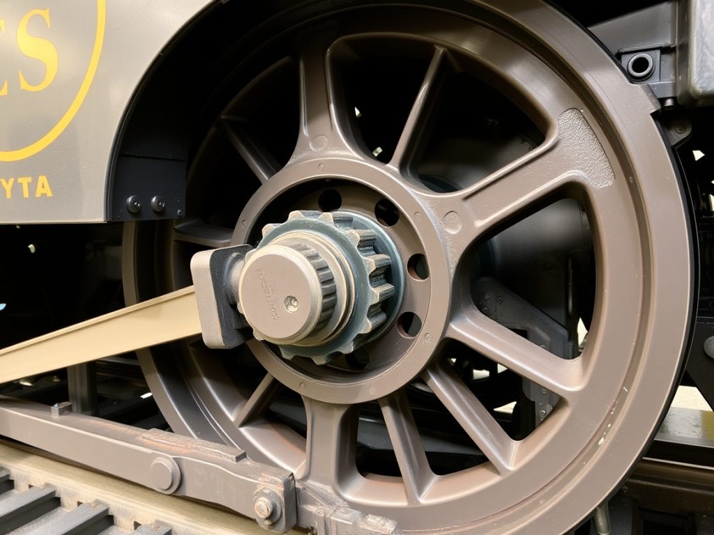
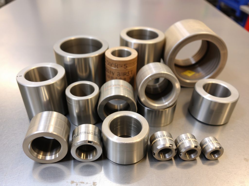
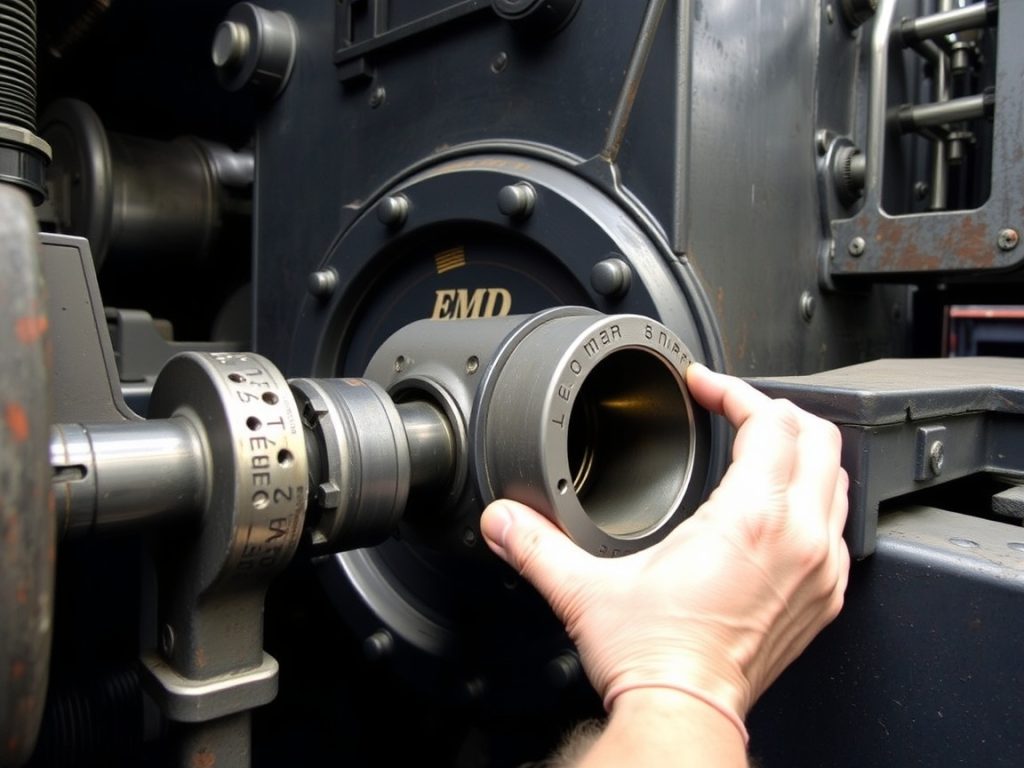
Since bearing failures account for over 60% of EMD 645/710 engine breakdowns, you must select bimetallic alloys that withstand the extreme thermal cycling and shock loads these powerplants generate. The 45-degree V-engine configuration places unique angular stresses on bearing surfaces that require specialized metallurgy considerations. For main bearings, choose babbitt-based alloys with steel backing—they’ll provide superior load capacity under vertical axial forces while maintaining conformability. The bimetallic properties of aluminum-tin combinations excel in connecting rod applications where reciprocating stresses dominate.

You’ll need lead-based overlays between 0.015–0.030″ thickness for anti-scuffing protection during mixed lubrication conditions. These overlays prevent seizure when oil films break down under high temperatures. Alloy performance depends on your specific application: aluminum-tin maintains ductility above 300°F for thermal resistance, while babbitt alloys offer better fatigue limits for sustained loading.

Select segmented designs for main bearings to minimize thermal distortion. Make sure your chosen alloy matches the torque multiplier ratios you’re using—differential stress during tightening can compromise bearing integrity if alloy strength ratings are inadequate.

Maintaining Oil Quality Through Filtration and Contamination Control

oil filtration and monitoring

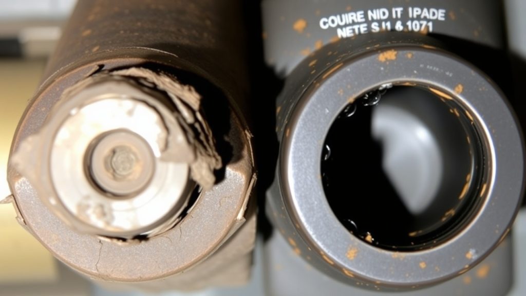
Proper bearing alloy selection becomes meaningless if contaminated oil destroys the bearing surfaces you’ve carefully specified. You must implement thorough filtration techniques to maintain oil integrity throughout your EMD locomotive’s lubrication system.

Install micron-rated filters capable of capturing particles ≥10 microns before they reach bearing surfaces. Replace these filters according to EMD maintenance schedules, typically aligning with 2,000-hour lubricant change intervals. Deploy multi-stage filtration combining primary and secondary filters to eliminate sludge, metal particles, and water contamination.

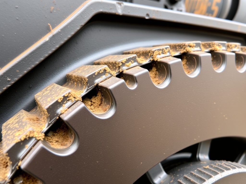
Address contamination sources systematically by sealing oil reservoirs against atmospheric moisture and dust ingress. Inspect lubrication lines regularly for corrosion or blockages that restrict oil flow. Install desiccant breathers or implement nitrogen blanketing in oil tanks to reduce moisture absorption.

Monitor oil levels consistently—low levels cause aeration while overflow creates contamination risks. Effective heat dissipation through proper oil circulation prevents thermal breakdown that compromises lubrication quality. Conduct regular oil analysis testing every 500-1,000 service hours, checking viscosity, particulate counts, and acidity levels to detect degradation early.

Implementing Pre-Startup Lubrication Procedures and Valve Operations

pre startup lubrication procedures

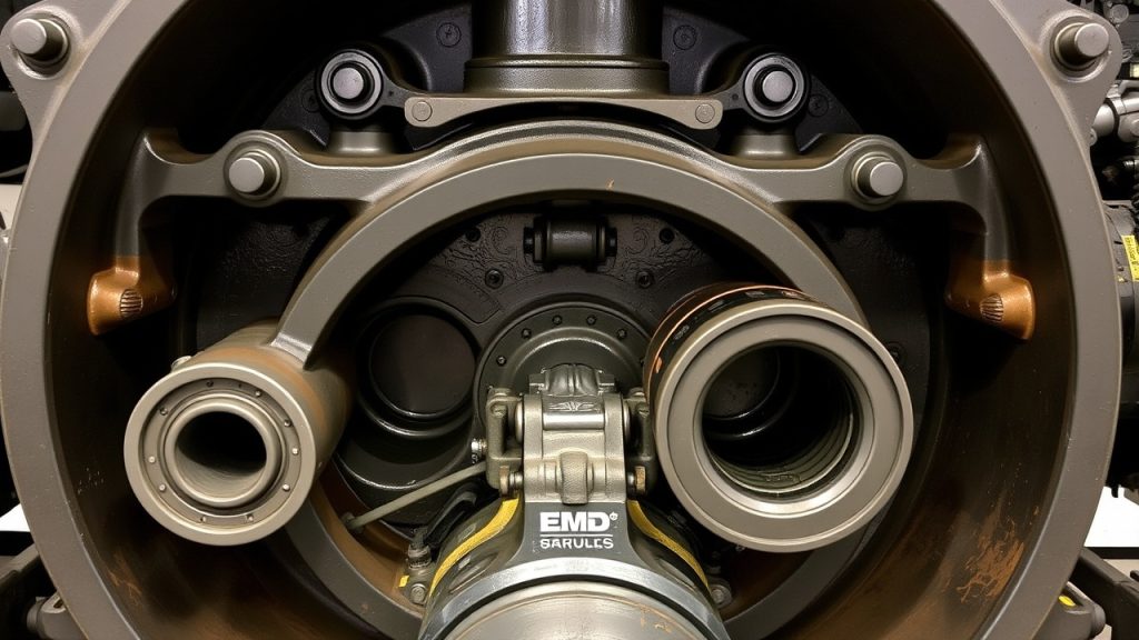
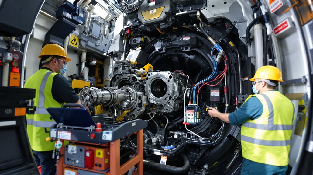
Before you engage the starter motor, establish complete lubrication coverage throughout your EMD locomotive’s bearing surfaces by executing systematic pre-startup procedures. Activate your auxiliary motor-driven pumps 35 minutes before operation to guarantee turbocharger bearing protection. Verify your pre-lube system parameters including oil level gauges and pump pressures to confirm adequate flow distribution.

Conduct thorough valve leakage inspection by examining turbocharger check valves for oil circulation blockages. Test your strainer functionality—discharge pressure exceeding 30 psi indicates dangerous blockages requiring immediate attention. Inspect bearing sprayer nozzles for clogging that compromises oil mist delivery to critical zones.

Execute pre lube synchronization by coordinating auxiliary pump activation with main oil pump engagement. Maintain minimum 1.3 kg/cm² pressure throughout startup sequences. Monitor your pressure gauges continuously and verify that emergency shutdown protocols activate below threshold levels to prevent catastrophic bearing damage during dry startup conditions.

Installing High-Quality OEM-Compliant Replacement Bearings

oem compliant replacement bearing installation

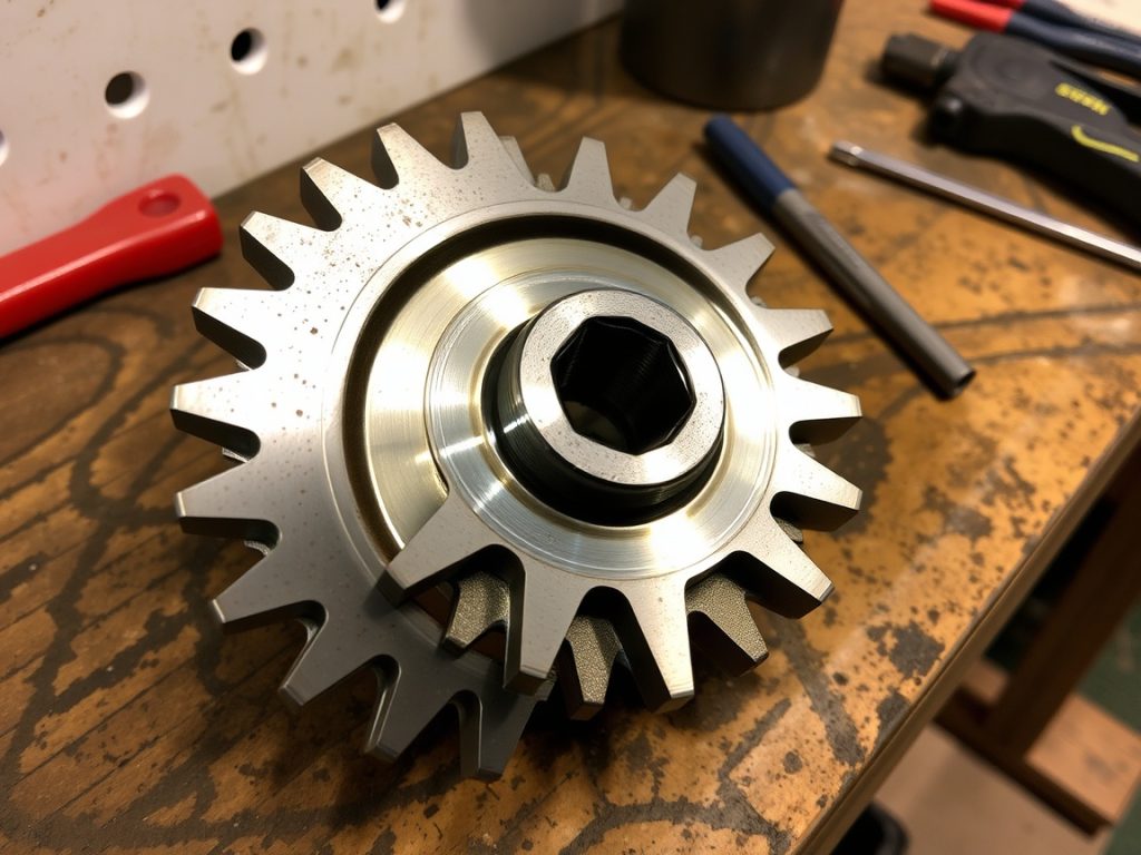
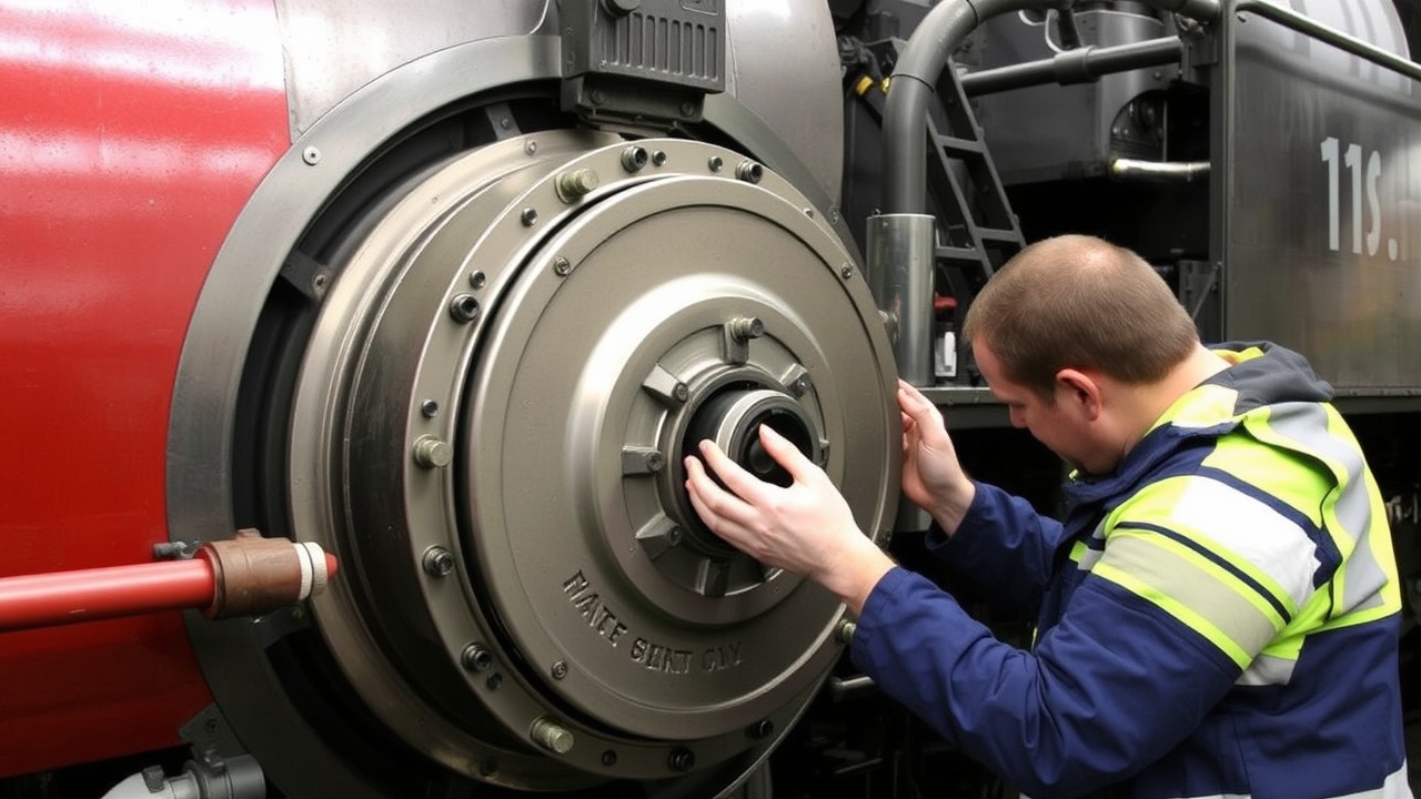
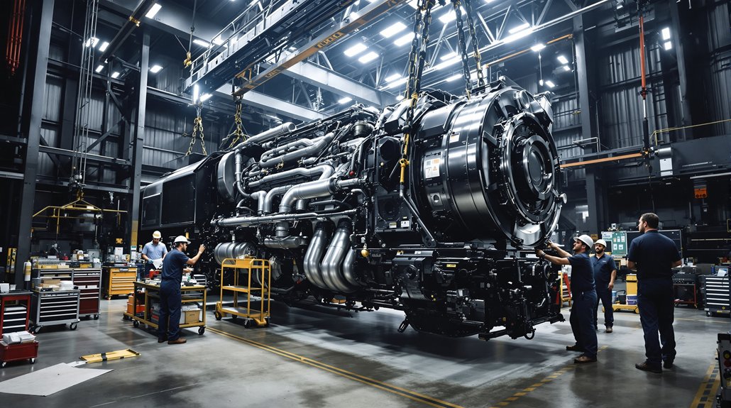
When bearing lubrication problems persist despite proper maintenance, you’ll need to install high-quality OEM-compliant replacement bearings that meet exact manufacturer specifications. You must prioritize ISO-certified suppliers and reference EMD’s component numbering system to guarantee geometric precision and material consistency throughout the installation process. Your precision installation procedures require calibrated torque tools, progressive tightening methods, and electronic measurement devices to maintain critical tolerances within 0.1mm specifications. Consider selecting bearings with specific oversize or undersize dimensions such as .093 Oversize or .031 Undersize variants to accommodate worn shaft conditions and restore proper clearances.

OEM Specification Compliance

Since bearing failures can cascade into catastrophic engine damage, you must install replacement bearings that precisely match OEM specifications to restore original performance parameters. OEM part compatibility guarantees direct fitment with original equipment designs, eliminating clearance deviations that cause lubrication failures. Bearing geometry optimization through contour shaping replicates factory load-bearing capacity, preventing premature wear.

ComponentOEM Part NumberCritical Specification
Main Bearing (Front)8455862Multi-layered lining thickness
Connecting Rod Upper08354118Clearance tolerance ±0.001″
Camshaft Bearing8071176Surface treatment compliance
Drive Gear Bushing8039671Metallurgical composition

You’ll prevent over/under-lubrication risks by maintaining tight clearance tolerances. Splenitizing and surface treatments must meet strict OEM standards for wear resistance, guaranteeing aftermarket suppliers don’t exceed metallurgical deviations beyond factory specifications. High-quality bearings constructed from heat-resistant alloys provide superior durability in demanding locomotive operating environments where extreme temperatures can compromise standard bearing materials.

Precision Installation Procedures

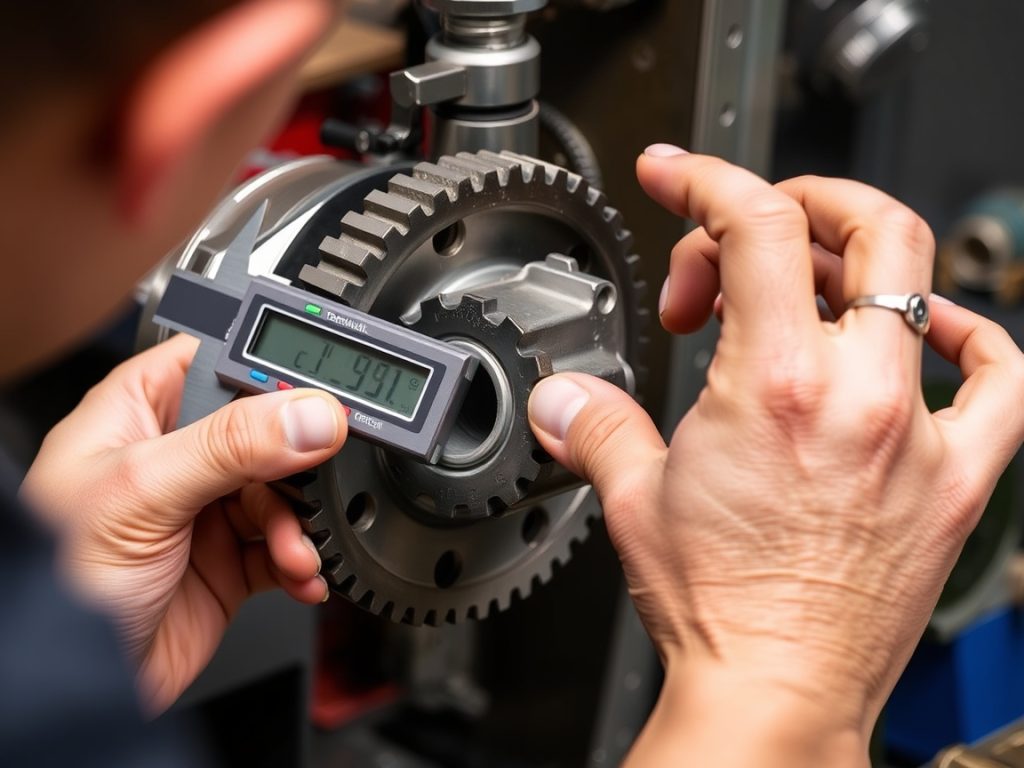
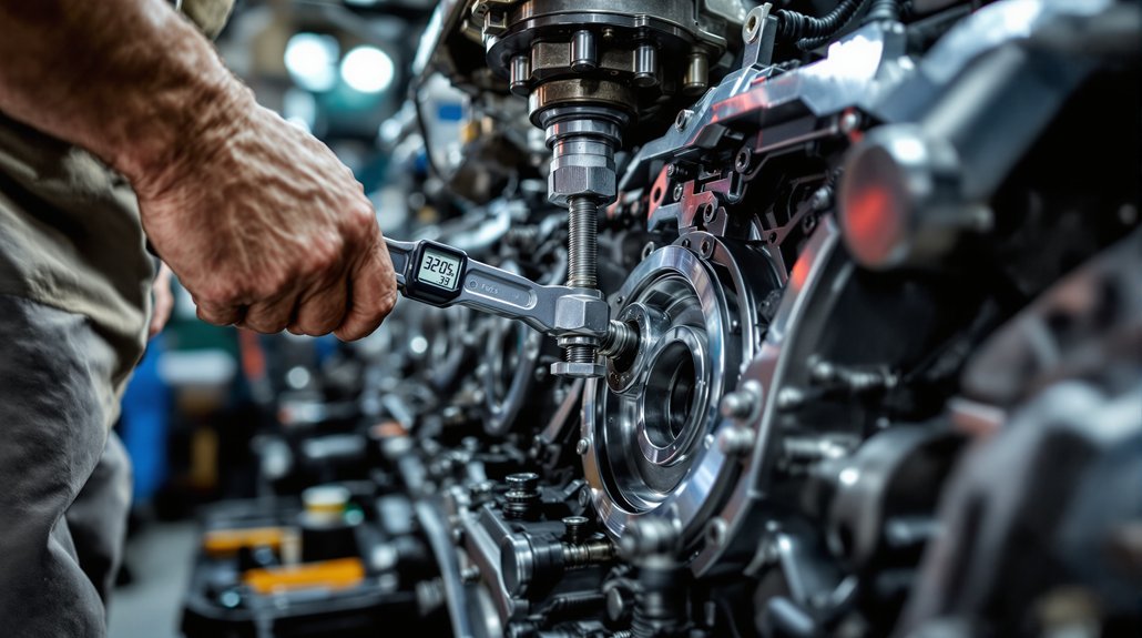
Proper bearing installation requires methodical execution of precise procedures that build upon OEM specification compliance to achieve factory-level performance restoration. You’ll need to verify crankshaft straightness using dial indicators across all ten bearings before proceeding. Inspect bearing recesses thoroughly for debris, then lubricate bearings internally before bearing seating. Load bearing caps from the rear to prevent crankshaft damage during installation.

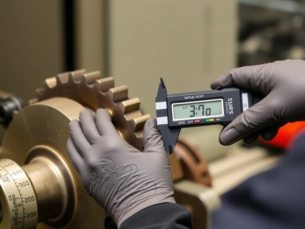
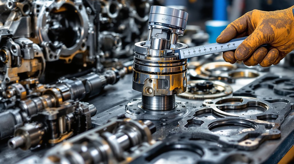
Use ball micrometers to verify wall thickness and measure interference fits within 0.0005″ using precision gauges. Apply precision torque to A-frame bolts following specifications to prevent distortion. Perform assembly at 1-2M temperatures with thermally matched components. Check radial clearances under operating temperature, then conduct post-installation run-in at reduced RPM for proper break-in. Replace bearings one at a time to maintain proper oil clearance specifications throughout the installation process.

Monitoring Oil Cooler Performance and Heat Management Systems

oil cooler performance monitoring

Although oil cooler performance directly impacts engine longevity, you must conduct thorough testing under full-load conditions to obtain accurate performance data. Position thermometers in the water pump discharge elbow to measure oil inlet temperatures, ensuring the engine reaches full-rated load and speed during testing. Maintain temperature stabilization at 70–80°C (160–175°F) for valid water inlet measurements.

Monitor lube oil outlet and cooling water outlet temperatures continuously to detect cooling inefficiencies that compromise oil cooler efficiency. Track turbo inlet pressure differentials affecting lubrication flow, adjusting throttle positions as needed to prevent overheating. Implement effective heat management strategies by dynamically controlling fan and shutter systems to maintain stable engine water temperatures. Avoid throttle position No. 3 until water temperature exceeds 54.5° C (130° F) to prevent thermal cycling damage to cooling components.

Conduct bi-monthly oil analysis for viscosity and contaminants per MI 1760 standards. Check filter differential pressures regularly, replacing filters every two years following EMD guidelines. Inspect oil strainer seals and housings for leaks that cause pressure drops, compromising bearing lubrication.

Preventing Cross-System Contamination in Multi-Pump Configurations

preventing contamination in pumps

When multiple pump systems operate within the same lubrication circuit, contamination can migrate between components through shared oil passages, compromising bearing protection across the entire system.

You’ll need rigorous component segregation protocols to maintain system integrity. Install sealed centrifuge filters with bypass circuits to isolate clean oil streams from contaminants, following EMD 16-645 engine specifications. Deploy dual-seal Bearing Lubrication Units with separate clean/dirty oil chambers to prevent recontamination between pump circuits.

Implement dedicated pressure reliefs to prevent inter-system pressure differentials that could force contaminants across seals. Maintain operating pressures below 50 psi for cross-linked components to prevent seal extrusion. Install differential pressure sensors at pump interfaces to detect imbalances indicating seal wear.

For contamination prevention, enforce cleaning sequence protocols that prioritize component reconditioning before reintroducing parts into multi-pump systems. Document all critical measurements before cleaning components to establish baseline tolerances for rebuilt assemblies. Use pressure relief valves on each pump circuit to prevent backflow between systems, ensuring complete isolation during maintenance operations.

Using Diagnostic Tools for Predictive Bearing Maintenance

predictive bearing maintenance tools

Beyond implementing robust contamination controls across multi-pump systems, you’ll need sophisticated diagnostic tools to catch bearing deterioration before catastrophic failures occur. Advanced signal processing techniques like Variational Mode Decomposition (VMD) outperform traditional methods by eliminating modal mixing issues that mask early-stage faults. Your fault detection capabilities improve dramatically when you integrate envelope analysis with calibrated vibration sensors designed for high-speed applications.

Essential diagnostic components for predictive maintenance include:

  1. Real-time data acquisition systems capturing weak fault signatures from multiple bearing locations simultaneously
  2. VMD-enhanced signal processing frameworks decomposing complex vibration patterns into analyzable modal components
  3. Machine learning algorithms trained on EMD-generated intrinsic mode functions for adaptive fault classification
  4. Specialized maintenance tools including offset bearing wrenches and precision lubricant applicators for targeted interventions

You must synchronize high-frequency sensor data while filtering electrical noise to guarantee accurate bearing condition assessments under variable load conditions. Research demonstrates that GNN-AdaBoost algorithms achieve over 98% accuracy in distinguishing between normal operation and bearing faults across different operational scenarios.

Frequently Asked Questions

How Often Should Bearing Clearances Be Measured During Routine Maintenance Intervals?

Like clockwork maintaining precise timing, you’ll measure bearing clearances annually per vendor specifications for critical components. However, you can extend intervals to two years if differential pressure monitoring systems are installed. Monitor bearing wear patterns continuously through predictive systems that detect anomalies before failure occurs. Always align maintenance frequency with EMD Service Bulletins, documenting clearance measurements to guarantee safe operational limits and prevent catastrophic bearing failures.

What Torque Specifications Are Required for Main Bearing Cap Installation Procedures?

You’ll need to apply 500-800 ft-lbs for initial main bearing cap installation procedure, with 650 ft-lbs recommended for verifying bore dimensions. Always retighten after thermal cycling to compensate for material expansion. Use specialized main bearing wrench sets like 8219512 or 8155363 for precision. Lubricate all threads before tightening and support tools through oil pan openings. Verify final bore measurements meet 8.249″-8.252″ specifications after proper torquing.

Can Synthetic Oils Be Safely Mixed With Conventional Mineral-Based Locomotive Lubricants?

Like mixing premium gasoline with regular fuel, you’ll compromise performance when combining oils. While synthetic compatibility exists chemically with mineral lubricants, you’ll dilute synthetic benefits and risk additive clashes. Follow EMD’s lubrication standards strictly—avoid routine mixing unless explicitly authorized. You must perform full system flushing before switching, verify additive compatibility through laboratory analysis, and use pre-approved syn-blend formulations to maintain warranty protection and peak bearing performance.

Which Infrared Temperature Ranges Indicate Critical Bearing Overheating Conditions Requiring Immediate Shutdown?

You’ll encounter critical overheating indicators when bearing temperatures exceed 200°F above ambient or reach absolute thresholds of 300-350°F. These readings demand immediate shutdown protocols to prevent catastrophic failure. Monitor HBD systems for temperature gradients exceeding 15-20°F across bearing surfaces, as these signal imminent breakdown. Don’t ignore sustained readings above baseline benchmarks—execute emergency停车procedures immediately when critical thresholds are breached to protect locomotive integrity.

How Do Ambient Temperature Changes Affect Optimal Oil Viscosity Selection Recommendations?

You’ll need to adjust oil viscosity selection based on temperature fluctuations in your operating environment. Higher ambient temperatures require higher-viscosity oils to maintain protective lubrication films, while cold conditions demand lower-viscosity formulations to prevent bearing starvation. You should select multi-grade synthetic blends that resist thermal thinning and thickening. Monitor your HBD systems closely during seasonal changes, as temperature fluctuations directly impact lubrication effectiveness and bearing protection.

7 High-Voltage Diodes for Railway Rectifier Applications

7 High-Voltage Diodes for Railway Rectifier Applications

You’ll need high-voltage diodes rated for 2,000-2,500A continuous current with voltage specifications ranging from 24V-110V DC to 25kV AC for railway rectifier applications. These diodes must comply with EN 50155 standards and withstand thermal cycling from -40°C to +85°C while maintaining ≤1.2V forward voltage drop. Critical features include surge protection up to 25kA fault current capacity, integration with 6-24 pulse rectifier configurations for harmonic reduction, and real-time monitoring capabilities for locomotive traction systems. Advanced specifications and selection criteria await your consideration.

Key Takeaways

  • High-voltage railway diodes must handle 15kV-25kV AC with current ratings up to 2,000A for traction applications.
  • Forward voltage drop should remain ≤1.2V at rated current to minimize power losses in rectifier circuits.
  • Diodes must comply with EN 50155 standards and withstand 0.7-1.25× nominal voltage ranges for railway certification.
  • Junction temperatures must stay below safety thresholds with thermal cycling from -40°C to +85°C operational ranges.
  • Multi-pulse rectifier configurations (6, 12, or 24-pulse) require matched diode sets for effective harmonic distortion reduction.

Voltage and Current Specifications for Railway Power Systems

railway power system specifications

Railway power systems operate across five distinct voltage categories, each demanding specific diode characteristics to guarantee safe and reliable rectification. You’ll encounter 24V-110V DC for auxiliary systems, 750V-1500V DC for traction networks, and 15kV-25kV AC for overhead transmission lines. Each category requires precise current rating calculations to handle peak operational loads.

For traction applications, you must specify diodes with current ratings up to 2,000A while maintaining minimal voltage drop across the junction. EN 50155 compliance mandates your diodes withstand 0.7-1.25× nominal voltage ranges, with transient tolerance reaching 1.4× for ≤100ms periods. High-voltage substations operating at 72kV require surge-rated diodes exceeding 25kA fault current capacity.

Your rectifier design must account for voltage drop limitations—typically ≤1.2V forward drop at rated current—to maintain system efficiency. Temperature derating factors become critical above 70°C, directly affecting both current rating and voltage drop characteristics under sustained railway operations. Power source transitions frequently cause voltage interruptions where diodes must continue rectification despite momentary drops to 0V for periods up to 20ms.

Thermal Management and Environmental Durability Standards

railway thermal management standards

Meeting precise voltage and current specifications means nothing if your diodes can’t survive the punishing thermal and environmental conditions found in railway operations. You must maintain maximum junction temperature below safety thresholds while managing thermal cycling between -40°C and +85°C operational ranges.

Critical thermal management parameters include:

  1. Thermal resistance (RθJC) quantifying heat transfer from junction to case
  2. ΨJT parameters enabling rapid Tj estimation via case temperature measurements
  3. Temperature differential (ΔT) restricted to ≤10K between ambient and initial junction temperature
  4. Continuous monitoring at ≥1 sample/hour during accelerated aging tests

Environmental durability testing follows IEC 60068-2-67 standards, maintaining 85°C ±2°C with 85% ±5% relative humidity. Advanced thermal management employs phase-change materials and composite structures for enhanced heat dissipation. Dynamic voltage cycling optimizes power loss distribution, while proper heatsink placement determines whether you’ll use RθJC or ΨJT thermal resistance values for system design calculations.

ECPE’s working groups specifically address power semiconductor reliability for railway applications, providing industry consensus on testing protocols and qualification standards. Advanced thermal management employs phase-change materials and composite structures for enhanced heat dissipation. Dynamic voltage cycling optimizes power loss distribution, while proper heatsink placement determines whether you’ll use RθJC or ΨJT thermal resistance values for system design calculations.

Compliance With International Railway Electronics Regulations

railway electronics compliance regulations

You’ll need to navigate three critical regulatory frameworks when implementing high-voltage diodes in railway rectifier systems: EN 50328 standards for railway power supply equipment, IEEE traction power requirements, and IEC certification protocols. These regulations establish mandatory performance thresholds for voltage stability, fault protection, and electromagnetic compatibility that directly impact your diode selection and circuit design decisions. Your compliance strategy must address each framework’s specific testing requirements, as failure to meet any single standard can result in certification rejection and operational safety risks. Railway rectifier systems must also meet EN 50155 requirements for electronic equipment operating conditions, design specifications, and integration protocols to ensure reliable performance across all rail vehicle applications.

EN 50328 Standards

Compliance with EN 50328 establishes the foundation for deploying high-voltage diodes in railway traction power systems, where this European standard specifies mandatory requirements for fixed installations of electronic power converters across railways, tramways, light rail, and underground systems.

Your diode selection must meet stringent performance criteria that directly impact converter efficiency in harsh electrical environments. The standard mandates specific testing protocols for semiconductor devices:

  1. Type testing under simulated traction system stresses
  2. Insulation testing for AC/DC interfaces per Table 8 criteria
  3. Short-circuit protection validation following railway safety standards
  4. Thermal management assessment under variable load conditions

You’ll need to guarantee your high-voltage diodes demonstrate reliability during dynamic load variations typical in accelerating trains, while maintaining voltage stability and meeting the durable semiconductor material requirements specified for railway traction applications. Adherence to established protocols enhances security by ensuring your diode implementations follow proven railway electronics standards.

IEEE Traction Requirements

Beyond EN 50328’s European framework, IEEE standards provide the international backbone for railway traction electronics, with IEEE 16-2020 establishing non-negotiable performance benchmarks that your high-voltage diodes must satisfy across global rail networks. You’ll encounter stringent voltage tolerances requiring precise semiconductor material specifications and manufacturing tolerances that directly impact diode reliability during operation.

Your designs must withstand extensive testing protocols including surge immunity assessments, temperature cycling from -40°C to +70°C, and mechanical stress evaluations. IEEE 2752-2023 mandates dual grounding systems with protective ground resistance below 1Ω, ensuring safe fault current dispersion. Critical survivability specifications include thermal derating rules and high dv/dt handling capabilities to manage transient voltage spikes from catenary systems while maintaining fail-safe redundancy mechanisms. These requirements provide uniform design specifications that enhance safety and reliability across all railway control apparatus implementations.

IEC Certification Protocols

While IEEE standards establish the operational framework, IEC certification protocols form the regulatory cornerstone that validates your high-voltage diodes against international railway safety and performance mandates. IEC testing encompasses thorough validation through IECEE third-party laboratories that replicate operational conditions including thermal cycling from -40°C to 85°C and vibration stress per IEC61373.

Your certification processes must address four critical validation areas:

  1. Safety Integrity Levels (SIL) – Components rated SIL 1-4 based on critical functions
  2. EMC Compliance – Electromagnetic compatibility per EN50121-3-2 standards
  3. Environmental Durability – Thermal management and insulation coordination validation
  4. Documentation Requirements – Complete design parameters, safety margins, and test reports

Mutual recognition agreements streamline cross-border approvals, ensuring your diode modules meet international railway electronics regulations while maintaining operational safety margins. IEC TC 9 develops specialized standards for railway and metropolitan transport systems that directly impact diode certification requirements.

Traction Substation Integration and Performance Requirements

traction substation performance requirements

As railway systems shift from traditional motor-generator sets to modern thyristor-based rectifiers, traction substations must accommodate increasingly complex integration requirements that directly impact system performance and reliability. You’ll need to configure these systems for continuous operation at high currents while maintaining stable DC output across variable load ranges.

ParameterSpecificationCritical Impact
Current Rating2,500A continuousThermal management
THD Compliance<5% at 80% loadPower quality
Power Factor>0.95 laggingGrid efficiency
Overload Capacity150% for 60sPeak acceleration
Voltage Regulation±2% no-load to full-loadSystem stability

Your traction system integration requires careful performance analysis of rectifier configurations—6, 12, or 24-pulse designs distribute harmonic currents effectively. You must guarantee rectifiers handle regenerative braking energy while maintaining IEEE standards compliance. Natural cooling designs reduce maintenance requirements, but you’ll need fault-tolerant modules for uninterrupted operation during component failures.

Modern installations utilize solid-state thyristor rectifier systems that provide superior reliability and efficiency compared to legacy mercury arc rectifiers and rotary converters.

Locomotive Generator Exciter Protection Systems

exciter protection systems efficiency

When locomotive generators operate under varying load conditions and environmental stresses, exciter protection systems form the critical defense layer that prevents catastrophic failures and guarantees continuous traction power delivery. Your exciter system requires thorough monitoring across multiple parameters to maintain operational integrity.

Temperature and current monitoring prevent output stage component damage through real-time thermal management and load limit enforcement. Short-circuit protection immediately isolates faults, while over-voltage protection guards against destructive spikes. Digital Signal Processor boards execute sophisticated fault detection algorithms that analyze:

  1. Speed-dependent excitation current variations during acceleration and braking cycles
  2. Voltage regulation stability under fluctuating load conditions
  3. Diode failure patterns in excitation circuit configurations
  4. Temperature thresholds across generator windings and control components

Redundant backup systems, including secondary protection circuits and battery-powered 24V inputs, guarantee continuous operation during primary system failures. Modern excitation devices utilize different excitation profiles to optimize power delivery efficiency during both drive-mode and braking-mode operations. CAN bus integration enables real-time diagnostic data transmission to vehicle computers, facilitating predictive maintenance and reducing unscheduled downtime.

Harmonic Reduction Through Multi-Pulse Rectifier Configurations

harmonic reduction in railways

You’ll achieve significant harmonic reduction by implementing 12-pulse rectifier configurations, which decrease total harmonic distortion from 40% in 6-pulse systems to approximately 10% through strategic harmonic cancellation. Your phase-shifted transformer design must incorporate 30° staggering between parallel 3-phase circuits to eliminate dominant 5th, 7th, and 11th harmonics that compromise power quality and threaten equipment integrity. This configuration requires precise transformer winding arrangements and auxiliary filtering to meet IEEE 519:2014 compliance standards while maintaining operational safety margins in high-voltage railway applications. Modern railway systems increasingly utilize VSD converter loads in trainsets, which generate distinct harmonic profiles compared to traditional resistive loads and require specialized assessment methodologies for power quality evaluation.

12-Pulse Configuration Benefits

Multi-pulse rectifier configurations deliver substantial harmonic reduction by leveraging phase displacement between transformer secondary windings to cancel specific harmonic orders. You’ll achieve significant harmonic optimization through strategic pulse efficiency implementation, where twelve-pulse systems inherently eliminate characteristic harmonics while eighteen-pulse configurations push THD performance below 3%.

Your pulse configuration selection directly impacts system performance:

  1. Twelve-pulse systems reduce grid THD to 15.2% under inductive loads
  2. Eighteen-pulse rectifiers achieve ~7.36% THD without additional filtering
  3. Multi-pulse designs minimize DC ripple content and voltage fluctuations
  4. Active injection circuits enhance lower-pulse system mitigation capabilities

You must balance manufacturing complexity against harmonic performance when selecting pulse counts. Higher configurations require specialized transformer windings but deliver superior grid compliance, reducing your dependency on extensive filtering systems for railway applications. The general equation h = n * (p +/- 1) defines the relationship between pulse number and resulting harmonic frequencies in multi-pulse converter systems.

Phase-Shifted Transformer Design

Phase-shifted transformer design achieves harmonic cancellation through precise angular displacement between multiple rectifier units, where Y-Δ dual-transformer configurations generate the critical 15° phase differences required for 24-pulse rectification systems. You’ll need to implement dual-transformer designs with Y-Δ and Δ-Y connections to create these exact phase shifts. Primary side current management through transformer impedance guarantees proper flux balance while maintaining safety standards for high-voltage operations. Phase shift control loops dynamically adjust secondary voltages to counteract harmonic injection, reducing 5th and 7th order components effectively. Epoxy resin construction enhances thermal stability in your transformer cores, while shielded insulation safely handles 10kV to 35kV inputs. This configuration delivers compliant THD reduction for modern rail applications.

Maintenance Optimization and Overload Capacity Features

maintenance and overload optimization

When implementing maintenance optimization for high-voltage railway rectifier diodes, you must establish systematic protocols that integrate electrical continuity testing, thermal imaging diagnostics, and calibrated DVOM verification procedures to ascertain operational reliability.

Your maintenance techniques require bi-annual scheduling to prevent critical failures. Implement visual inspections for physical damage detection, while thermal imaging identifies heat distribution anomalies indicating internal defects. Temperature monitoring through thermal sensors tracks operating thresholds, preventing catastrophic overheating.

For overload protection, you’ll need these critical features:

  1. Bidirectional power flow support for regenerative braking energy capture
  2. Surge protection circuits blocking voltage spikes exceeding safe parameters
  3. Modular redundancy preventing cascading failures during overload conditions
  4. Optimized reverse recovery time enabling rapid current switching

Modular multi-cell designs replace thyristor-based systems, enhancing efficiency. Regular component replacements address aging before failure occurs. Airflow optimization ensures proper heat dissipation in high-voltage environments, while infrared monitoring provides real-time thermal diagnostics for early fault detection.

You may also like to read – How to Select EMD Traction Rectifier Diodes

Frequently Asked Questions

What Are the Typical Costs for Replacing High-Voltage Diodes in Railway Systems?

You’ll face diode pricing of $125 per HVD 1005 board for 34-40 kV applications. Your replacement budget must account for substation spacing—25 kV systems need boards every 32 km versus 50 kV systems every 64 km. You’re looking at higher upfront costs but reduced deployment density with higher voltages. Plan for MOV-protected boards to extend service life and minimize unplanned replacements in your maintenance budget.

How Long Do Railway Rectifier Diodes Typically Last Before Requiring Replacement?

Like mechanical clockwork, you’ll find railway rectifier diodes typically last 15-25 years under normal operating conditions. Key diode longevity factors include maintaining junction temperatures below 125°C and proper thermal management. You should monitor performance degradation indicators such as increased reverse leakage current exceeding 10µA and forward voltage drops deviating beyond ±0.1V specifications. Regular testing every 2-3 years guarantees safety compliance.

Can Existing AC Railway Systems Be Retrofitted With Modern Diode Rectifiers?

You’ll face significant retrofitting challenges when upgrading AC railway systems with modern diode rectifiers, requiring careful voltage compatibility analysis and thermal management integration. Modern diode efficiency improvements of 15-25% justify conversion costs, but you must evaluate existing infrastructure constraints, cooling system adequacy, and protective relay coordination. You’ll need phased implementation strategies to minimize service disruptions while ensuring safety compliance with updated rectifier specifications and harmonic distortion limits.

What Backup Power Options Exist if Primary Rectifier Diodes Fail Unexpectedly?

Like medieval castle fortifications protecting against siege, you’ll need redundant systems when rectifier diodes fail catastrophically. Deploy parallel rectifier banks with automatic switchover capabilities, ensuring 99.9% availability during primary failures. Install power storage via UPS batteries providing 2-8 hours autonomy for critical signaling loads. Implement load-shedding protocols prioritizing safety systems over passenger amenities. Hot-swappable modular designs enable rapid maintenance without complete shutdown, maintaining operational continuity during component replacement procedures.

Are There Specific Safety Procedures for Handling High-Voltage Railway Diodes During Maintenance?

You’ll follow strict safety protocols when handling high-voltage railway diodes. Wear insulated PPE and obtain Electrical Permits before starting work. De-energize systems through proper disconnect procedures, then conduct visual inspections for cracks or corrosion. Apply voltmeter tests to verify grounding effectiveness and use multimeter shunt measurements for leakage quantification. These maintenance guidelines require authorized traction lineman certification and documentation of all test results for compliance tracking.

How to Select EMD Traction Rectifier Diodes

How to Select EMD Traction Rectifier Diodes

You’ll need to match forward current ratings exceeding 1,000A for heavy-duty EMD locomotives while ensuring reverse voltage capabilities meet your DC traction system requirements with 20-30% safety derating below maximum VRRM. Select fast-recovery diodes with synchronized recovery times to minimize switching losses in 12-pulse configurations. Consider thermal management through appropriate package selection—TO-208 for 600A+ applications—and verify vendor compliance with EN50328, IEC60146, and AAR certification standards. The complete selection process involves additional critical parameters and configuration strategies.

Key Takeaways

  • Select diodes with forward current ratings exceeding 1,000A and reverse voltage ratings ≥1.2 times continuous operating voltage.
  • Choose fast-recovery diodes with low reverse recovery time to minimize switching losses in high-frequency applications.
  • Use TO-208 or bolt-mount packages (DO-4/DO-5) with proper thermal management for 600A+ traction system requirements.
  • Ensure vendor compliance with EN 50328, IEC 60146, and AAR/RIA qualifications for railway applications.
  • Consider 12-pulse parallel configurations to reduce harmonics and improve current sharing in EMD locomotive systems.

Understanding EMD Locomotive Power Requirements and Operating Conditions

locomotive diode performance requirements

EMD locomotives demand rectifier diodes that withstand extreme operational variability across power ranges from 1,350 hp in legacy FT models to over 4,000 hp in modern high-voltage IGBT systems. You’ll encounter 600V DC traction motor systems fed by AC generators through rectification circuits, where diodes convert high-voltage AC to stable DC for propulsion. Your locomotive efficiency depends on rectifiers managing transient voltage spikes during acceleration/deceleration cycles while maintaining thermal stability across 900-950 rpm engine speeds.

Consider traction control requirements when selecting diodes for 8-, 12-, 16-, or 20-cylinder configurations. You must account for regenerative braking‘s reverse power flow, which tests diode reverse recovery characteristics. Dynamic braking operations generate substantial heat, demanding robust surge capacity and vibration-resistant mounting. Temperature extremes, altitude variations, and electromagnetic interference challenge component durability. Your diode selection must comply with IEEE standards while supporting modular maintenance accessibility and fault tolerance through ground protective relays. Proper corrosion management strategies must be implemented during installation to prevent electrical contact degradation that could compromise rectifier performance over the locomotive’s operational lifespan.

Evaluating Forward Current and Reverse Voltage Ratings for Traction Applications

traction diode selection criteria

Forward current and reverse voltage ratings form the electrical foundation of your rectifier diode selection process, determining whether components can handle the power demands and voltage stresses inherent in EMD traction systems.

Your forward current selection must align with traction motor demands, typically requiring 1000+ A continuous capacity for heavy-duty locomotives. Calculate total current based on power requirements—277 kW ÷ 560 V equals 495 A maximum—then factor in regenerative braking peaks reaching 1050 A.

Forward current ratings must exceed 1000 A continuous capacity to handle traction motor demands and regenerative braking peaks in locomotive applications.

For reverse voltage ratings, match your traction system’s DC output requirements:

  1. 825 V systems for urban transit applications
  2. 1500-1650 V configurations for standard rail operations
  3. 3000-3300 V setups for heavy-haul locomotives
  4. Derating by 20-30% below maximum reverse voltage (VRRM) for safety margins

Select devices rated ≥1.2 times continuous operating voltage. Modern 3-phase generators require specialized rectifier configurations to ensure optimal power conversion efficiency. Apply 120% safety margins for transient currents during braking scenarios, ensuring compliance with EN50328/IEC60146 standards while maintaining ideal performance under dynamic operating conditions.

Analyzing Reverse Recovery Time and High-Frequency Performance Characteristics

diode performance and efficiency

While forward current ratings establish your diode’s steady-state capabilities, reverse recovery time determines performance during critical switching changes that define traction system efficiency. You’ll need to evaluate reverse recovery characteristics against your system’s switching frequency to minimize parasitic losses that accumulate during commutation cycles.

Select semiconductor grades with low minority carrier storage, particularly fast-recovery diodes that reduce switching delays in high-frequency applications. The material composition directly affects charge storage; modern substrates using advanced materials minimize recovery time while maintaining ruggedness for frequent load reversals.

Your high frequency performance depends on synchronized recovery times across multi-unit stacks to prevent phase imbalance. You must account for dynamic resistive losses during abrupt current shifts and guarantee diode ratings exceed peak transients by adequate safety margins. Implement compact layouts reducing stray inductance, and utilize transient thermal analysis to track cyclic losses from reverse recovery events in your traction system design. Rotating ring rectifiers in diesel electric locomotives require matching of recovery characteristics across diode arrays to maintain balanced conversion from AC to DC for traction motors.

Selecting Appropriate Package Types and Thermal Management Solutions

diode package thermal management

You’ll need to match your diode package’s current capacity to your EMD traction system‘s operational requirements, considering that TO-254 packages handle moderate currents while TO-208 configurations support 600A+ applications. Your heatsink design must accommodate the specific thermal resistance characteristics of your chosen package type, with metal tab configurations requiring direct thermal interface contact and bolt-mounted packages demanding proper torque specifications. You must evaluate whether passive cooling through natural convection meets your thermal dissipation requirements or if enhanced cooling systems become necessary for high-power density installations. High power bolt mount packages like DO-5 and DO-4 provide secure attachment to PWB or metal heat sinks through threaded bolt connections for maximum thermal transfer efficiency.

Package Current Capacity

When selecting EMD traction rectifier diodes, package current capacity determines both system reliability and thermal performance under the demanding conditions of railway applications. You’ll need to evaluate specific parameters that directly impact package efficiency and diode longevity in high-power traction systems.

Consider these critical capacity factors:

  1. Average vs. Peak Ratings – TO-252II packages handle 6A continuous current while supporting 40A surge capabilities for acceleration demands
  2. Thermal Derating Curves – Junction temperatures approaching 150°C require current reduction to maintain reliability margins
  3. Parallel Configuration Benefits – Multiple diodes in 12-pulse systems distribute thermal loads and improve current sharing
  4. Dynamic Load Response – Variable frequency operation (40-120Hz) affects RMS current calculations and thermal cycling stress

Package dimensions of 10.0 x 6.6 mm provide standardized footprints for efficient heat dissipation in compact traction converter designs.

Match package specifications to your system’s maximum operating conditions.

Heatsink Design Requirements

Since thermal management directly determines diode reliability and system performance, your heatsink design must integrate package selection with calculated thermal resistance paths. Select aluminum alloy heatsink materials with thermal conductivity ≥200 W/mK and extended fin surfaces optimizing convection paths. Your thermal calculations should determine maximum junction temperature limits using Rth = (Tj – Ta)/P – Rthjc – Rthcs, factoring worst-case power dissipation scenarios.

Choose TO-220 packages with pressfit mounting for direct mechanical contact, eliminating solder-induced thermal barriers. Apply 50-100 µm thermal grease layers while maintaining surface planarity within 50 µm tolerances. For isolated configurations, account for additional thermal resistance from insulation plates. Install heatsinks before lead soldering to prevent warpage stress compromising thermal interface integrity. Full bridge rectifier structures require insulation between diodes when using non-isolated tab packages to prevent electrical interference.

Cooling System Selection

After establishing proper heatsink thermal resistance paths, you must evaluate cooling system architectures that match your traction rectifier’s power dissipation profile and operating environment. Your selection directly impacts diode junction temperatures and system reliability under locomotive operating conditions.

Consider these critical cooling methods for EMD traction applications:

  1. Air-cooled systems – Single-module designs like A300485 simplify thermal management through forced convection with integrated fans
  2. Thermal interfaces – Grafoil pads and thermal compounds optimize heat transfer between diode packages and heatsinks
  3. Hybrid cooling – Combined air-liquid systems handle extreme power densities exceeding 1,000V operation
  4. Thermal monitoring – Real-time temperature sensors prevent thermal runaway and extend component life

Match cooling capacity to your rectifier’s continuous and peak power requirements while considering maintenance accessibility. During power-up scenarios, proper thermal management becomes critical when charging current limiting components like A300631 face their highest stress conditions.

Determining Series and Parallel Configuration Requirements

parallel 12 pulse configurations required

For DC traction substations, you should consider parallel 12-pulse configurations to minimize 5th, 7th, 17th, and 19th harmonics in AC networks. Series-parallel 12-pulse setups use fewer diodes but demand precise voltage balancing. Your transformer tap ratios must match the configuration: parallel setups often require √3 turns ratio adjustments between Y and D windings. These rectifier systems must comply with EN50328 standards to ensure proper integration with European railway infrastructure.

Assessing Peak Surge Current Capacity and Overload Protection

surge current protection evaluation

While proper series-parallel configurations establish your system’s voltage and current distribution, the diodes must withstand electrical stresses that exceed normal operating conditions. Surge tolerance evaluation becomes critical when EMD locomotives experience sudden load spikes, regenerative braking transients, or grid disturbances that can destroy inadequately rated components.

Your diode specification comparisons should focus on these surge parameters:

  1. Non-repetitive surge current ratings – 1N400X series handles 30A for 8.3ms half-sine loads, while S3D04065A manages 390A for 10μs pulses at 25°C
  2. Temperature derating factors – S3D series drops to 265A at 110°C, requiring thermal margin calculations
  3. I²t surge energy capacity – Match fuse ratings to diode limits (3.7A²s for 1N4001) for coordinated protection
  4. Recovery charge specifications – Lower Qc values reduce switching losses in AC/DC conversion systems

You’ll need external MOVs or surge arrestors when expected transients exceed your diodes’ maximum surge ratings. Always verify these specifications against current manufacturer datasheets since component revisions can alter critical surge handling capabilities.

Considering Environmental Factors and IP Rating Requirements

environmental and reliability standards

Since EMD locomotives operate across diverse climatic zones—from arctic freight corridors to desert mining operations—your diode selection must account for environmental stresses that can dramatically exceed laboratory test conditions. You’ll need IP65-rated enclosures minimum to prevent moisture ingress and dust accumulation that compromises electrical performance.

Environmental FactorRequired Specification
Temperature Range-40°C to +100°C continuous
Humidity Tolerance95% RH non-condensing
Vibration ResistanceIEC 61373 Cat 1 Class B

Material compatibility becomes critical when selecting lead-free grades like MY258A2, which must withstand chemical exposure from lubricants and coolants without degradation. Your diodes must demonstrate <1% power loss drift over 10,000+ operating hours to guarantee diode longevity.

Accelerated aging tests simulating freeze-thaw cycles, UV exposure, and saltwater corrosion help predict real-world performance. Proper cooling systems are essential to prevent overheating during rectifier operation, as excessive temperatures can lead to premature diode failure and reduced conversion efficiency. Prioritize components meeting EN 50155 railway standards to minimize environmental impact while maintaining reliability across extreme operating conditions.

Vendor Selection and Compliance With Railway Industry Standards

vendor compliance and support

You must verify that your chosen vendor demonstrates proven compliance with EN 50328 and IEC 60146 standards through documented type testing and certification records. Evaluate the manufacturer’s track record in supplying rectifier diodes specifically for EMD traction systems, ensuring they maintain AAR/RIA qualifications and can provide transparent material traceability documentation. Your vendor assessment should prioritize suppliers who offer extensive technical support for EMD AR10 alternator integration and can guarantee consistent production quality through EN-standardized verification processes.

Railway Standards Compliance

When specifying EMD traction rectifier diodes, adherence to established railway industry standards guarantees operational safety, system interoperability, and regulatory compliance across diverse transit applications. Modern rectifier technology must navigate complex compliance challenges while maintaining performance specifications.

Critical standards governing your selection include:

  1. IEEE Std 1653.2-2020 – Defines design parameters for uncontrolled rectifiers up to 1500 V DC, establishing manufacturing and testing protocols
  2. EN 50328 – European standard mandating performance criteria, safety protocols, and reliability benchmarks for traction rectifiers
  3. IEC 60146-6 – Specifies operational parameters including voltage tolerance thresholds and thermal management requirements
  4. NEMA RI-9 – Provides guidelines for overload capacity ratings and service classifications

You’ll need third-party certification audits for high-voltage applications, thorough documentation packages, and conformance testing verification to ascertain your diode selections meet regulatory requirements.

Qualified Vendor Assessment

Qualified vendors must demonstrate thorough compliance with railway industry standards before you can consider their EMD traction rectifier diodes for critical applications. Your vendor evaluation process should verify RISQS prequalification status, guaranteeing suppliers meet health & safety requirements and ISO 9001 quality management standards. For North American operations, confirm AAR certification through their rigorous approval process including design submissions and facility assessments.

Examine supplier reliability through documented safety cases compliant with CENELEC EN50126/29 standards and IEC 61508 functional safety requirements. Review certification evidence including test reports and conformity statements for electrical systems. Validate that vendors maintain current ISA assessments from accredited bodies like Ricardo or TUV SUD. Ascertain suppliers demonstrate proactive risk management and establish continuous monitoring processes for design changes, maintaining traceability throughout their qualification lifecycle.

Frequently Asked Questions

What Diagnostic Features Help Identify Failing Rectifier Diodes in EMD Locomotives?

Detecting defective diodes demands decisive diagnostic tools for accurate analysis. You’ll monitor voltage imbalances exceeding 25,000V limits through continuous tracking systems. Thermal sensors flag “hot diode” faults triggering alarm modes, while Hall-effect current transducers provide galvanic isolation during diode testing procedures. Fault code displays specify diode-related failures with operational restrictions. Historical logging stores recurring failure data, enabling mathematical analysis of thermal management patterns and voltage spike correlations for precise maintenance scheduling.

How Do You Match Diodes for Current Sharing in Parallel Configurations?

You’ll achieve ideal current distribution in parallel operation by selecting diodes from identical production lots with matched forward voltage characteristics within ±2% tolerance. Implement equal series resistance (1-3Ω) for each branch to compensate Vf mismatches. Mount diodes on shared thermal substrates with symmetrical PCB trace lengths to minimize parasitic resistance disparities. Pre-test IV curves to verify consistency and guarantee uniform thermal coefficients for stable current sharing performance.

What Fusing Strategies Work Best for Individual Versus Common Protection Schemes?

Choosing fusing strategies is like threading a needle—precision matters. You’ll find individual protection excels when you need selective isolation and fault localization in multi-bridge systems, preventing cascading failures across parallel rectifier paths. Common protection simplifies maintenance while centralizing load management, though you sacrifice granular control. For 12-pulse traction systems, individual fusing typically outperforms common schemes by enabling targeted diagnostics and maintaining √3 winding balance during fault conditions.

How Does PWM Switching Frequency Affect Rectifier Diode Selection and Losses?

PWM impact on rectifier selection escalates exponentially with frequency. You’ll encounter reverse recovery losses proportional to fsw×Q, where stored charge becomes critical above 50kHz. Diode efficiency degrades through junction capacitance charging cycles and increased I²R losses from peak currents. You must prioritize Schottky diodes for frequencies exceeding 100kHz, or shift to SiC technology above 500kHz to maintain acceptable loss ratios below 2-3%.

What Thermal Interface Materials Optimize Heat Transfer in Traction Rectifier Assemblies?

You’d think slapping any thermal pad onto rectifier diodes would suffice—until junction temperatures soar beyond ratings. For traction assemblies, you’ll need silicone pads delivering 4.9 W/mK thermal conductivity, ensuring efficient heat transfer from semiconductor junctions to heat sinks. Phase change materials optimize interface bonding by conforming to surface irregularities under operational temperatures. Select materials meeting rail industry thermal cycling standards for reliable performance.

You may also like to read – EMD Locomotive Specification Book SD40-SPEC8054-31DEC65

7 Signs Your WABCO Locomotive Brake Diaphragm Needs Replacement

7 Signs Your WABCO Locomotive Brake Diaphragm Needs Replacement

You’ll recognize a failing WABCO locomotive brake diaphragm through seven critical signs: audible air leaks with hissing sounds from brake chambers, delayed brake response during emergency situations, dashboard warning lights indicating pressure imbalances, unusual grinding or creaking noises during brake operation, sluggish pedal engagement compromising stopping power, pressure drops of 60-70 PSI within minutes during testing, and brake warning system alerts from insufficient air supply. These symptoms signal immediate replacement requirements to prevent catastrophic brake failure and guarantee operational safety compliance with FRA standards.

Key Takeaways

  • Audible air leaks and hissing sounds from brake chambers during service brake activation indicate diaphragm seal failure.
  • Sudden pressure drops of 60-70 PSI within minutes when engine is off and brakes are applied.
  • Sluggish brake pedal engagement and delayed response times that compromise emergency stopping power and safety.
  • Dashboard brake warning lights activate due to pressure imbalances and insufficient air supply in brake chambers.
  • Unusual noises like diaphragm creaking, air intake hissing, or pressure pops during brake operation cycles.

Air Leaks and Pressure Loss in Brake Chambers

Three critical indicators signal failing WABCO locomotive brake diaphragm through air system compromises that directly impact operational safety.

You’ll detect audible air leakage during service brake activation, with distinct hissing sounds emanating from brake chambers and exhaust ports. This air leakage occurs exclusively when you’re braking, indicating compromised diaphragm seals that can’t maintain proper pressure regulation.

Monitor for sudden pressure drops during system tests. You’ll experience 60-70 PSI tank losses within minutes when the engine’s off and brakes are applied. Your compressor will struggle maintaining ideal pressure, leading to DOT test failures in specific chambers. Excessive pressure can cause leaks in valves, gaskets, and seals throughout the brake system.

Rapid 60-70 PSI losses during brake tests indicate failing diaphragms causing compressor strain and DOT compliance failures.

Watch for recurrent leaks despite component replacements. New ABS valves may continue leaking after installation due to debris or rust damaging replacement diaphragms. You’ll notice that proper pressure regulation becomes impossible when worn piston rings allow oil and air to escape, creating chronic system inefficiencies that compromise braking performance.

Delayed Brake Response and Reduced Effectiveness

deteriorating brake diaphragm hazards

When your locomotive’s brake diaphragm begins deteriorating, you’ll notice increasingly sluggish pedal engagement that compromises critical stopping power during emergency situations. High-speed braking becomes particularly dangerous as worn diaphragms can’t generate sufficient pressure quickly enough to maintain safe deceleration rates. Most critically, continued operation with compromised diaphragms risks catastrophic rupture under maximum braking loads, potentially causing complete brake system failure when you need it most. Temperature extremes exceeding 150°C can reduce diaphragm elasticity by 50%, leading to reduced braking force and delayed response times that further compromise locomotive safety.

Slow Pedal Engagement

During routine locomotive operations, you’ll notice slow pedal engagement manifesting as a delayed response between brake application and actual braking force delivery. Failed diaphragm sealing creates cracked surfaces and frayed edges that compromise airflow efficiency, reducing pedal sensitivity during critical braking sequences. You’ll experience increased brake stroke travel as warped diaphragm alignment prevents rapid airflow redirection to brake chambers.

Degraded diaphragm materials lose flexibility needed for proper sealing cycles, causing delayed charging sequences that counteract compressor output. This results in slower diaphragm response times to control signals and incomplete lifting during brake release. You’ll notice diminished engagement feedback as unbalanced pressure differentials create irregular actuation speeds. Diaphragm sticking due to debris further worsens engagement delays, requiring continuous re-pressurization efforts that strain overall air circuit reliability. The compromised diaphragm prevents proper exhaust port sealing, which is essential for maintaining the valve’s hold position and preventing air leakage during brake application.

High Speed Inefficiency

As locomotive speeds increase beyond 40 mph, you’ll encounter diminished brake response effectiveness that directly correlates with diaphragm deterioration in your WABCO brake system. You’ll notice extended time lag between brake initiation and actual deceleration, with worn diaphragms restricting pressure reduction signals through brake pipes.

This high speed instability manifests as unequal air distribution between cars, causing inconsistent brake cylinder pressure build-up across your consist. Your auxiliary reservoirs won’t maintain required pressure during rapid deceleration, slowing response times considerably. Compromised automatic brake valve cut-out functionality delays full engagement, while brake system calibration becomes unreliable. You’ll experience excessive slack action and run-in phenomena that disrupt train integrity. These performance deficiencies violate FRA operational standards and extend stopping distances beyond federal safety margins.

Diaphragm Rupture Risks

If your WABCO brake diaphragm suffers a rupture, you’ll face immediate and severe brake response degradation that compromises your locomotive’s stopping capability. Ruptured diaphragms disrupt critical pressure regulation, preventing proper brake cylinder pressure maintenance and causing continuous air loss that undermines emergency braking effectiveness.

Key rupture indicators requiring immediate attention:

  • Uncontrolled air flow to brake cylinders during lap position operations
  • Pressure equalization failure between control and reservoir systems
  • Delayed emergency response due to compromised triple valve engagement
  • Excessive brake shoe overheating from continuous traction cycles
  • Inconsistent brake pipe pressure affecting multi-car coordination

Implement systematic diaphragm inspection techniques focusing on visual tears and pressure differential testing. Your rupture detection methods must include regular pressure monitoring and response time measurements to guarantee WABCO Type 26 compliance standards. The diaphragm rupture creates conditions similar to angle cock closure scenarios, where affected brake components fail to receive adequate air pressure for proper operation.

Dashboard Warning Lights and System Alarms

brake system warning indicators

When your WABCO locomotive’s brake diaphragm begins to fail, you’ll notice critical warning systems activate on your dashboard as the first line of defense against potential brake failure. Your brake warning light will illuminate due to pressure imbalances detected in the brake chambers, while pressure sensor alert codes will trigger from insufficient air supply or continuous leaks throughout the system. You must also monitor master cylinder fluid warnings in hybrid brake systems, as diaphragm failure can compromise both pneumatic and hydraulic brake components simultaneously.

Brake Warning Light Activation

Multiple warning systems activate when WABCO locomotive brake diaphragms begin failing, providing you with critical early detection capabilities before complete system breakdown occurs.

Your brake warning lights illuminate when specific pressure thresholds are exceeded during brake diagnostics. System calibration monitors detect diaphragm degradation through measurable performance deviations that trigger dashboard alerts.

Key activation triggers include:

  • Pressure drops exceeding 5 psi/minute during brake pipe testing
  • Airflow rates above 60 CFM detected during AFM system checks
  • Main reservoir pressure imbalances with brake cylinder readings
  • Brake cylinder pressure loss greater than prescribed maintenance limits
  • Control pressure reductions causing irregular exhaust valve operations

You’ll notice these warnings during pre-operational inspections when diaphragm seals deteriorate or when relay valve operations can’t maintain proper pressure equilibrium between system components. According to maintenance protocols, low air pressure warning devices should properly activate at or above 55 psi to ensure system reliability.

Pressure Sensor Alert Codes

Although WABCO locomotive brake systems generate specific diagnostic trouble codes (DTCs) through advanced pressure monitoring networks, you’ll encounter these alerts as critical safety indicators requiring immediate attention. SPN 802 FMI 4 signals low voltage in axles 1+2+differential circuits, while SPN 792 FMI 5 indicates open circuits in wheel sensors. Codes 2581 60 5/6 reveal pump motor supply voltage deficiencies requiring immediate sensor troubleshooting protocols.

DTC 796 identifies pressure modulation valve current below specifications, demanding thorough wiring inspections. When sensor mismatch errors appear, implement calibration techniques to verify plausibility between multiple pressure readings. These codes often stem from wiring harness abrasion, connector continuity failures, or excessive air gaps between sensors and pole wheels, necessitating systematic diagnostic procedures. Salt water intrusion creates conductive pathways that generate intermittent codes and cross-connections between circuits, leading to erratic system behavior.

Master Cylinder Fluid Warnings

Beyond pressure sensor diagnostics, WABCO locomotive brake systems rely on master cylinder fluid monitoring to maintain hydraulic integrity and prevent catastrophic brake failures. Your fluid level monitoring system triggers immediate alerts when levels drop below minimum reservoir marks, demanding swift action to prevent air infiltration.

Critical master cylinder fluid warnings include:

  • Low-level sensor alerts requiring immediate refill to MAX marks before operations
  • Contamination prevention failures when non-WABCO fluids compromise seals and calipers
  • Reservoir breathing system malfunctions from aftermarket caps allowing debris ingress
  • Cross-contamination warnings when mixing incompatible hydraulic fluid types
  • Visual contamination indicators showing discolored fluid or particle debris

You’ll need immediate system flushing when contamination prevention protocols fail, as compromised fluid degrades rubber components and triggers system-wide hydraulic failures. When high oil consumption occurs in brake system components, it typically signals deteriorated seals requiring immediate replacement to prevent complete system failure.

Unusual Noises During Brake Operation

brake system abnormal sounds

When WABCO locomotive brake systems begin producing abnormal sounds, you’re witnessing early warning indicators that demand immediate attention before catastrophic failure occurs.

Unusual grinding from worn bearings signals metal-on-metal contact requiring immediate inspection. Diaphragm creaking indicates rubber deterioration under thermal stress, compromising seal integrity. Monitor air intake hissing—degraded diaphragm seals allow unregulated airflow into brake chambers, reducing braking efficiency.

Piston knocking suggests reduced lubrication or wear in the diaphragm piston stem assembly. You’ll hear pressure pops when deformed diaphragms release trapped air irregularly during brake applications. Valve chatter occurs from inconsistent diaphragm-operated closures, affecting system pressure regulation.

System resonance transmits through brake components when diaphragm movement creates vibrations. Emergency brake thump indicates diaphragm actuation responses deviating from normal engagement speeds. Like Westinghouse air brakes, WABCO systems require precise component integration to maintain optimal locomotive safety standards. Document all abnormal sounds with their operational phases—this data helps technicians identify specific component failures and prioritize replacement schedules before complete system breakdown endangers locomotive operations.

Parking Brake System Malfunctions

parking brake system failures

Parking brake system failures pose immediate safety hazards that extend beyond the audible warnings discussed previously. When your WABCO locomotive’s brake diaphragm deteriorates, you’ll notice critical parking brake malfunctions that demand immediate attention. These failures compromise both primary safety systems and emergency procedures.

System diagnostics reveal five primary indicators of diaphragm-related parking brake problems:

  • Warning lights remain illuminated despite proper release procedures, indicating faulty switch contacts
  • Incomplete brake disengagement occurs when control levers can’t fully release retained chamber pressure
  • Emergency brake applications fail to engage properly during critical safety tests
  • Air system integration malfunctions cause uneven pressure distribution between primary and secondary reservoirs
  • Compressed air leakage persists after release attempts, signaling diaphragm seal failure

You must address these parking brake system failures immediately. Compromised diaphragms create unpredictable brake behavior that threatens operational safety and regulatory compliance.

Exhaust Brake Performance Problems

exhaust brake performance issues

Although parking brake failures present immediate safety concerns, exhaust brake performance deterioration creates equally dangerous operational hazards that manifest through specific measurable symptoms. You’ll notice inefficient exhaust flow regulation during dynamic braking operations, which directly impacts your locomotive’s braking efficiency. When diaphragms fail, exhaust air flow becomes erratic, causing inconsistent pressure gradients across train units during braking applications.

Your system will struggle with prolonged brake recharge times, particularly evident in 200-car trains that take up to 2.5 times longer to repressurize after running releases. You’ll experience irregular brake cylinder pressures, with BC pressures dropping 2.7-3.6 PSI lower in longer trains during catastrophic braking scenarios. These pressure irregularities often coincide with excessive smoke emissions from the exhaust system, indicating incomplete combustion that compounds braking performance issues. Additionally, your EBS system will detect pressure differentials between brake circuits and report sudden changes in engine drag torque control responses, ultimately forcing the system into limp-home mode when redundancy failures occur.

Maintenance Schedule and Service Indicators

rigorous brake maintenance protocols

Systematic maintenance protocols prevent catastrophic brake failures and guarantee WABCO diaphragm systems maintain peak performance throughout their service life. You’ll need to establish rigorous maintenance intervals that include daily inspections and planned service schedules to identify diaphragm replacement requirements before system failures occur.

Rigorous maintenance intervals and daily inspections prevent catastrophic WABCO brake failures while ensuring peak diaphragm system performance throughout service life.

Your daily inspection routine should monitor critical performance indicators that signal impending diaphragm deterioration:

  • Verify pressure gauges maintain 7-10 bar during operation and check for air leaks
  • Test control valve response times and governor functionality for delayed operations
  • Monitor brake cylinder pressure development consistency during applications
  • Check exhaust valve seating during brake release cycles
  • Drain moisture from brake reservoirs and document pressure readings

You must maintain extensive service documentation including FRA Part 229-compliant testing records and systematic component overhaul schedules. Replace pneumatic slack adjusters every 10 years and apply proper WB stencils with depot symbols. Document all anomalies for predictive maintenance planning. When conducting quarterly overhauls, disassemble exhausters in HEPA-filtered environments using wet-cleaning methods to prevent contamination and ensure optimal component inspection.

Frequently Asked Questions

How Much Does a WABCO Locomotive Brake Diaphragm Replacement Typically Cost?

You’ll face replacement pricing starting around $243 for a WABCO 4231057000 diaphragm brake cylinder, but total costs escalate considerably with labor, system calibration, and mandatory safety inspections. Specialized technician fees, downtime compensation, and potential component upgrades can triple your initial investment. Key maintenance tips include scheduling replacements during planned service windows and considering multi-component packages for fleet operations to reduce per-unit costs and minimize locomotive service interruptions.

Can I Replace the Brake Diaphragm Myself or Need Professional Service?

Like threading a needle in a hurricane, DIY replacement of WABCO locomotive brake diaphragms demands extreme precision you likely can’t achieve safely. You’ll need specialized cage bolts, calibrated torque drivers, and factory-certified materials meeting FRA compliance standards. Improper alignment or over-tightening risks catastrophic brake failure. Professional assistance guarantees manufacturer specifications, warranty preservation, and regulatory compliance. Don’t gamble with locomotive safety—certified technicians possess the expertise and equipment necessary.

What Tools Are Required for WABCO Brake Diaphragm Installation Procedures?

You’ll need specific tools for proper brake maintenance during WABCO diaphragm installation. Essential equipment includes calibrated M16x1.5 torque wrenches, diaphragm spring compressors, and alignment pins for precise positioning. Tool selection must include pressure testing gauges, air leakage detection equipment, and Rocol 1000 lubricant applicators. Don’t forget safety gear: respirator masks, steel-toe boots, and flame-resistant clothing. Compressed air sources and brake line pressure test kits guarantee complete system verification post-installation.

How Long Does a Typical Brake Diaphragm Replacement Service Take?

You’ll typically complete brake diaphragm replacement within 2-4 hours, depending on system accessibility and component age. Your brake maintenance timelines must account for mandatory 20-second pressure release waits, relay valve realignment, and post-installation testing procedures. Service efficiency measures include pre-positioning tools, following WABCO’s sequential protocols, and conducting thorough pressure calibration. You’ll need additional time for documentation requirements and E-5 system verification testing.

Are Aftermarket Diaphragms Compatible With Original WABCO Brake Chamber Specifications?

You’ll find aftermarket compatibility varies greatly with WABCO brake chambers. While some aftermarket diaphragms meet dimensional specifications like 156.0mm diameter and M16 x 1.5 threading, diaphragm performance often differs from OEM standards. You’re risking pressure regulation failures and material degradation without proper elastomer grades. Verify exact stroke measurements, operating pressure ratings, and temperature ranges (-40°C to +80°C) before installation to guarantee safe braking performance.

Diaphragm Replacement Intervals for Railway Safety Equipment

Diaphragm Replacement Intervals for Railway Safety Equipment

You must replace railway brake system diaphragms according to strict federal intervals that range from 368 days for conventional locomotives to 1,840 days for advanced air dryer-equipped systems under 49 CFR 238.309. DMU units allow 500-day cycles, while WABCO systems require 368-day replacements for compliance. Delayed maintenance triggers regulatory violations, equipment failures, and safety risks that can halt operations. Understanding these classification systems and their specific requirements will help you optimize maintenance schedules while ensuring full regulatory compliance.

Key Takeaways

  • Standard diaphragm replacement intervals range from 368 to 1,840 days depending on locomotive type and air system configuration.
  • Systems with air dryers enable extended maintenance cycles, with 26-C systems allowing 1,840-day diaphragm replacement intervals.
  • Conventional locomotives without air dryers must follow 736-day replacement intervals established by federal regulatory guidelines.
  • DMU air dryers with integrated filtration systems permit shorter 500-day replacement intervals due to enhanced system protection.
  • Replacement schedules cannot be reduced without FRA approval and must include complete disassembly and thorough component inspection.

Regulatory Framework for Brake Equipment Maintenance Under 49 CFR 238.309

brake equipment maintenance regulations

When maintaining brake equipment under 49 CFR 238.309, you must completely disassemble all pneumatically sealed components containing moving parts at prescribed intervals. This regulation mandates thorough cleaning, lubrication, and replacement of deteriorating parts across all brake system components, including air valves, reservoirs, and control units.

You’re required to conduct pneumatic sealing inspections at scheduled intervals regardless of operational history. Equipment becomes defective immediately upon discovering noncompliance with maintenance schedules. Deteriorated seals, lubrication failures, or component wear automatically trigger defect status, requiring resolution before returning to service.

You can’t reduce standard maintenance intervals without FRA approval. Alternative procedures require petitions demonstrating equivalent or superior safety levels per § 238.21 guidelines. Moving parts in pneumatic sealing systems need synchromatic inspection to maintain air-tight integrity. Maintenance inspections must prevent corrosion in precision-sealed units, with replacement intervals aligned to material degradation rates for continuous brake system reliability. Filtering devices or dirt collectors must be cleaned, repaired, or replaced as part of the mandatory maintenance process.

Maintenance Interval Classifications by Locomotive Type and Air System Configuration

maintenance intervals by locomotive

When you’re maintaining DMU air dryers, you’ll benefit from extended replacement intervals due to their integrated filtration systems that reduce contamination-related diaphragm degradation. Conventional locomotives require more aggressive scheduling because they lack these protective mechanisms and operate under higher cyclic stress loads. You must adjust your maintenance protocols accordingly, as DMUs typically allow 500-day intervals while conventional units demand the standard 368-day WABCO replacement cycle to maintain regulatory compliance. Systems without air dryers follow the 736-day intervals established by federal maintenance guidelines for enhanced operational efficiency.

DMU Air Dryer Benefits

Five distinct maintenance classification systems govern DMU air dryer operations, each designed to maximize equipment reliability while extending service intervals beyond standard pneumatic configurations. You’ll benefit from air dryer efficiency that enables 1,472-day level two maintenance cycles for semi-permanently coupled locomotives, compared to standard 368-day intervals. Your moisture control systems automatically drain condensation, reducing filter replacement frequency and preventing corrosion-related failures.

These extended intervals directly reduce operational costs while maintaining regulatory compliance under §229.29. You’ll achieve power efficiency through dry compressed air that minimizes brake system freezing and contamination risks. Alaska Railroad’s adoption of longer overhaul cycles demonstrates proven reliability. Your air dryer systems complement CCB configurations, providing redundancy that prolongs service between major overhauls while ensuring consistent performance in high-humidity environments. All maintenance activities require detailed records that include locomotive number, inspection dates, and technician signatures for regulatory compliance.

Conventional Locomotive Requirements

Conventional locomotives operate under significantly different maintenance protocols than DMU systems, requiring shorter replacement intervals and more frequent inspections due to higher operational stress and regulatory oversight. You’ll need to follow EMD’s 92–184 day inspection cycles while maintaining CFR Part 229 compliance. Diaphragm materials face accelerated degradation from chemical exposure and cyclic stress, particularly in high-usage applications where air systems exceed 30 psi static thresholds.

System TypeReplacement Interval
EMD Pneumatic Control92-184 days
Wabco Brake DiaphragmsPreemptive replacement
WAP/WAG Brake BlocksWear limit based
Air Test ConnectionsMinor maintenance cycle
Digital Control SystemsExtended with analytics

Your maintenance strategies must prioritize brake subsystems and valve mounting integrity to prevent failures that compromise operational safety. Performance indicators should guide repair timelines to ensure safety protocols dictate how urgent issues are addressed across all locomotive systems.

Extended Service Intervals for Advanced Brake Systems With Air Dryers

extended brake maintenance intervals

Although most railway brake systems require frequent maintenance intervals, advanced brake systems equipped with air dryers can extend your service schedules greatly beyond standard regulatory minimums. Air dryer effectiveness enables these sophisticated configurations to operate safely with dramatically reduced maintenance frequencies, transforming traditional maintenance paradigms.

Brake system innovations have revolutionized compliance intervals through three critical maintenance tiers:

  1. 26-L brake systems – You’ll achieve 1,104-day intervals with proper air dryer integration, reducing downtime costs greatly
  2. Dedicated coupled units – Your 26-L systems with air dryers qualify for 1,472-day extensions, maximizing operational efficiency
  3. Advanced architectures – CCB-1, CCB-2, KB-HS1, and Fastbrake systems allow 1,840-day intervals when you maintain 100% air dryer adoption

You must verify compatible engineer brake valves like PS-68, 26-C, or RT-2 configurations. These extended intervals require strict documentation on Form F6180-49A, but they’ll considerably reduce your maintenance burden while maintaining regulatory compliance. Main reservoirs must undergo hydrostatic pressure tests at intervals not exceeding 736 days to ensure continued operational safety.

Component Replacement Criteria and Deterioration Assessment Standards

component replacement assessment standards

Component replacement scheduling demands rigorous assessment protocols that go beyond simple time-based intervals. You’ll need to establish clear deterioration indicators through systematic evaluation methods that include visual inspection for cracks, fraying, or surface wear, thermal imaging to detect heat-related degradation, and ultrasonic testing for internal material integrity assessment.

Your replacement guidelines must incorporate hardness profiling to measure material composition changes and thorough service lifespan tracking through historical maintenance records. You can’t rely solely on manufacturer schedules—condition-based maintenance prioritizes inspection frequency based on actual usage patterns and operational stress.

Pre-service inspections are mandatory before revenue service, while post-accident evaluations require immediate assessment following collision events. You must align scheduled maintenance intervals with manufacturer-recommended cycles but adapt them based on specific operational conditions. Railway diaphragms require fail-safe design principles to prevent unsafe conditions during system malfunctions. Regulatory oversight through unannounced safety checks guarantees compliance with established deterioration assessment standards.

Impact of PS-68, 26-C, and ABDW Control Valve Systems on Maintenance Schedules

valve systems impact maintenance schedules

When implementing maintenance schedules for railway brake control systems, you’ll find that PS-68, 26-C, and ABDW valve configurations create distinctly different interval requirements that directly impact diaphragm replacement timing.

PS-68 valves present significant maintenance challenges with their 736-day intervals and heightened susceptibility to air contamination. You’ll need more frequent reactive maintenance due to early diaphragm deterioration, often requiring alignment with 31- or 92-service-day inspections to prevent subsystem failures.

26-C systems offer enhanced diaphragm longevity, extending replacement cycles to 1,840 days when equipped with KB–HL1/HS1 air dryers. This configuration reduces component wear substantially.

ABDW valves demand predictive diagnostics for efficient scheduling:

  1. Biennial pressure monitoring prevents catastrophic failures
  2. Service day-based maintenance maximizes replacement costs
  3. Quarterly diagnostic checks guarantee regulatory compliance under §229.27

You’ll achieve compliance by documenting air dryer integration status and maintaining audit-ready FRA Form records.

Level One Maintenance Requirements and 368-Day Critical Component Inspections

safety protocols for inspections

Five critical safety protocols govern Level One maintenance requirements, establishing mandatory 368-day inspection cycles that directly impact railway operational safety and regulatory compliance. You’ll conduct visual inspections examining diaphragm surfaces for perishment, fiber cracking, or structural thinning that compromises operational integrity. Your inspection frequency must align with 49 CFR §238.503 requirements, ensuring diaphragm performance meets federal standards for braking systems and pneumatic operations.

You’re required to perform pressure and leak testing validating diaphragm integrity against operational loads and unexpected pressure spikes during service. Critical components with safety risks—including braking diaphragms and pressurized pneumatic systems—demand immediate replacement when structural defects appear. You’ll document inspection results, component history, and renewal dates in maintenance logs for audit readiness. Training protocols require technician certification for specialized diaphragm testing using manufacturer guidelines integrated with railroad safety standards, ensuring qualified personnel handle safety-critical components during 368-day inspection cycles. Additionally, annual program reviews must be conducted to verify maintenance procedures comply with evolving federal safety standards and operational requirements.

Safety Testing Protocols and Pre-Departure Brake System Verification

pre departure brake checks required

You must complete thorough pre-departure brake checks before every terminal departure to guarantee diaphragm integrity and system compliance with Class I brake test requirements under §232.205. Your emergency application inspections verify that brake pipe communication remains uncompromised and that diaphragms can withstand the pressure differentials created during irreversible emergency stops. These mandatory verification protocols protect against catastrophic brake failures that could result from deteriorated diaphragm components compromising your train’s braking capacity. Train operations cannot commence with less than 85% operative brakes across all cars in the consist.

Pre-Departure Brake Checks

Before each train’s departure, you must conduct thorough brake testing protocols that form the cornerstone of railway safety compliance. Your pre departure procedures under 49 CFR part 215 require designated inspector oversight and extensive system verification. You’ll perform Class I brake tests ensuring brake pipe leakage remains ≤5 psi/min and air flow stays ≤60 CFM.

Critical brake inspection techniques include:

  1. System charging verification – achieving ≤15 psi differential from locomotive regulating valve settings
  2. 20 psi reduction testing – confirming every car’s brake response and 3-minute application retention
  3. Release confirmation checks – visual verification at ≤10 mph speeds ensuring complete brake disengagement

You must validate brake assignment through physical inspection or ETD monitoring, requiring ≥5 psi pressure differentials. Rear-of-train pressure compliance demands ≥75 psi minimum with ≤15 psi variance from locomotive settings. For freight trains operating in ECP brake mode, a qualified mechanical inspector must conduct the Class I brake test in accordance with § 232.205(c) compliance requirements.

Emergency Application Inspections

When emergency conditions arise, your inspection protocols must shift from routine verification to thorough safety validation under Activity 217E compliance requirements. Emergency inspections demand immediate prioritization of any defects discovered during diaphragm system assessments. You must conduct cross-functional verification of brake systems, including coupling alignment checks before equipment movement. Post-incident inspections become mandatory for brake components that fail during emergency applications.

Your compliance narratives must detail specific findings regarding diaphragm integrity under emergency conditions. Document safety appliance status, including tension handles and latching mechanisms that affect brake system performance. Coordinate with signal teams during joint inspections to guarantee interoperability between brake and signal systems. Upload inspection data weekly to FRA systems, with immediate corrections issued for any compliance violations discovered during emergency application testing. Emergency brake testing must include Class Three protocols for comprehensive system validation.

Industry Compliance Standards and Documentation Requirements for Railway Operators

railway compliance and documentation

Railway operators must navigate multiple regulatory frameworks that establish mandatory compliance standards for safety equipment maintenance and documentation. You’ll need to adhere to APTA rail standards, CSX proximity restrictions, and FMCSA regulations while maintaining thorough records for compliance audits.

Your documentation strategies must include hours-of-service logs with seven-day histories, medical examiner certifications, and safety incident tracking with strict reporting timelines. You’re required to maintain equipment release documentation and conduct annual MVR audits to guarantee operational eligibility.

Critical compliance failures that put lives at risk:

  1. Missing pre-movement inspections of couplers, lineups, and obstructions before equipment operation
  2. Inadequate flag person monitoring within 25 feet of main tracks during railcar movements
  3. Incomplete ELD system submissions to DOT compliance teams beyond the 24-hour deadline

You must implement three-step protection protocols, maintain wheel chock documentation, and guarantee all safety equipment inspections align with manufacturer intervals to avoid regulatory violations and operational shutdowns.

Frequently Asked Questions

Can Weather Conditions Affect Diaphragm Replacement Timing Beyond Standard Intervals?

Weather brutally assaults your diaphragms with relentless thermal cycling, moisture infiltration, and freeze-thaw destruction that’ll shred standard replacement schedules. You must accelerate maintenance intervals when experiencing extreme temperature swings, prolonged humidity exposure, or harsh winter conditions. Weather impact demands proactive seasonal maintenance adjustments – reducing intervals by 25-40% during severe conditions guarantees regulatory compliance and prevents catastrophic failures in safety-critical applications.

What Are the Cost Differences Between OEM and Aftermarket Diaphragms?

You’ll face significant cost differences between OEM and aftermarket diaphragms that extend beyond initial pricing. While aftermarket options appear cheaper upfront, OEM advantages include superior materials, regulatory compliance, and extended warranties that reduce long-term expenses. Aftermarket disadvantages encompass frequent replacements, potential AAR violations, voided warranties, and liability risks. You’re accepting substantial financial exposure when choosing non-OEM parts despite apparent savings.

How Do Altitude Changes Impact Diaphragm Performance and Replacement Schedules?

You’ll experience significant altitude effects on diaphragm performance due to pressure differentials and temperature extremes. Diaphragm materials deteriorate faster at high elevations from UV exposure, thermal cycling, and reduced air density affecting pressure regulation. You must shorten replacement intervals from standard 92-day schedules, implement frequent pressure testing, and specify altitude-resistant elastomers. You’ll need enhanced inspection protocols for cracking and recalibrate governors regularly to maintain regulatory compliance and prevent critical system failures.

Are There Visual Inspection Techniques to Identify Early Diaphragm Wear?

Like a detective examining evidence, you’ll spot early wear through systematic visual inspection before catastrophic failure occurs. You must check for hairline cracks, surface discoloration, and material degradation around stress points. Look for uneven thickness, frayed edges, or loss of elasticity when flexed. Document any bulging, pitting, or surface oxidation immediately. These early wear indicators demand immediate attention to prevent brake system compromise and regulatory violations.

Can Diaphragms From Different Manufacturers Be Mixed Within Same Brake System?

You shouldn’t mix diaphragms from different manufacturers within the same brake system due to critical diaphragm compatibility issues. Each manufacturer’s specifications differ in dimensions, materials, and pressure responses, creating dangerous mismatches. AAR standards require uniform components to prevent air leakage, pressure inconsistencies, and potential brake failures. Cross-manufacturer mixing violates FRA regulations, voids warranties, and increases derailment risks. Always use manufacturer specifications-compliant parts for regulatory compliance and system safety.

Why Do Locomotive Air Compressor Gasket Seals Fail?

Why Do Locomotive Air Compressor Gasket Seals Fail?

You’ll find gasket seals in locomotive air compressors often fail due to repeated pressure cycling, temperature swings, and chemical exposure that fatigue materials and degrade their integrity. Contaminants like dust or moisture accelerate abrasive wear and corrosion, while improper installation or skipped maintenance further compromise sealing. If you’re not using materials suited for these extreme conditions or neglect regular inspections, failures become inevitable. Understanding the specific points of stress and failure can help you take targeted preventive measures as you move forward.

Key Takeaways

  • Repeated thermal and pressure cycling causes material fatigue, cracking, and loss of gasket integrity.
  • Chemical incompatibility with lubricants, fuels, or condensate leads to rapid material degradation and corrosion.
  • Contaminants such as dirt, dust, and moisture erode gasket surfaces and compromise sealing effectiveness.
  • Improper installation practices, including incorrect torque or sealant use, create uneven sealing and early failure.
  • Design limitations or use of non-repairable components prevent effective maintenance, increasing the risk of persistent seal failures.

Material Challenges in High-Pressure and Thermal Environments

high pressure seal material challenges

When locomotive air compressors operate under high pressures and temperature fluctuations, gasket seal materials face relentless mechanical and chemical stress. You’ll see repeated thermal cycling causing expansion and contraction that leads to material fatigue and crack formation. Low thermal resistance polymers degrade quickly, losing their ability to maintain a tight seal. Pressure cycling further challenges these materials—insufficient compressive strength results in gaskets crushing, while sustained cyclic loading of metal seals can trigger ductile fractures. Rapid decompression events during pressure cycling often cause abrupt failures, especially in seals not designed for such extremes.

Chemical degradation is another threat. High-temperature gradients accelerate breakdown, and coolant leaks can create galvanic corrosion at metal interfaces. Moisture from condensate promotes pitting, especially in stainless steel and composite seals. Air Pressure Build Issues, such as slow or insufficient air pressure, often signal underlying gasket or seal failures—prompt inspection can help prevent broader system damage. Selecting gasket materials compatible with fluids and temperatures is essential. You’ll need to prioritize high compressive strength, thermal resistance, and chemical compatibility to effectively combat material fatigue and seal failure.

Design Limitations of Gasket and Valve Components

seal integrity and serviceability

When you select gasket and valve materials, you face compatibility issues with contaminants and fluctuating temperatures that quickly undermine seal integrity. Non-repairable component designs force full replacements rather than targeted fixes, increasing costs and downtime. To address recurring failures, you should specify robust valve geometries, use compatible materials, and prioritize components designed for serviceability. Modern railway air brake systems typically operate at high pressures, which can further stress gasket and valve seals if materials are not properly chosen for these conditions.

Material Selection Challenges

Selecting the right materials for locomotive air compressor gaskets and valve components demands attention to at least three interrelated factors: chemical compatibility, mechanical resilience, and the realities of modern compressor design. If you ignore material compatibility, you’ll face polymer degradation from diesel or lube oil exposure, and plasticizers leach out under high temperatures, weakening seals. Meanwhile, improper alloy selection leads to corrosion, especially in humid or condensing environments. Leaks in air compressor systems not only reduce efficiency but also increase operational costs over time. Thermal expansion mismatches between metals and polymers cause warping or leaks as temperatures fluctuate. To illustrate key material challenges:

ChallengeConsequencePractical Solution
Polymer degradationSeal crackingUse high-temp FKM elastomers
Alloy corrosionGasket pittingSpecify stainless alloys
Expansion mismatchLeak under cyclingMatch CTE of materials

Optimal material choices must balance cost, durability, and application-specific risks.

Non-Repairable Component Issues

Material suitability is just one side of the reliability equation; the inherent design limitations of non-repairable gasket and valve components introduce a different set of persistent challenges. You’ll find that suboptimal seal geometry can’t accommodate fluctuating pressure cycles or compensate for crankshaft wear, leading to accelerated leakage. Gasket adhesion suffers when shaft surfaces aren’t properly prepared or when leftover debris remains, leaving micro-pathways for gas escape. Inadequate grease application or excessive sealant blocks critical seal lands, compromising function.

Filtration systems often fail to remove fine particulates or sour gas contaminants, which degrade seal materials and disrupt adhesion. Reverse rotation and pulsation exposure—factors built into the component’s operating environment—can’t be mitigated once installed. Address these limitations by enforcing strict installation tolerances and improving filtration and surface preparation protocols. In the railway industry, WABCO compressors are essential for maintaining proper brake operation, so any failure in gasket seals can directly impact locomotive safety and performance.

Valve Design Weaknesses

Though robust materials form a critical foundation, inherent valve design weaknesses often undermine gasket and seal reliability in locomotive air compressors. If you overlook valve geometry, you risk introducing sharp corners or inadequate support, which create localized stress points and accelerate seal failure. Poorly designed sealing surfaces and uneven load distribution compound this problem, leading to premature gasket wear and leaks.

Continuous change in working volume during piston motion, as seen in reciprocating compressors, can also subject gaskets to variable pressures, increasing the likelihood of fatigue and failure. Manufacturing flaws, such as machining defects, further concentrate stress along sealing interfaces. Inadequate strain relief in valve assemblies amplifies fatigue on sealing surfaces, especially under cyclic loading. To address these issues, optimize valve geometry for smooth shifts, distribute loads evenly across gasket seating areas, and implement rigorous quality controls during manufacturing. Prioritizing these practical design improvements greatly enhances seal longevity and reduces maintenance demands.

Impact of Contaminants and Debris on Seal Longevity

contaminants shorten seal lifespan

When contaminants and debris infiltrate a locomotive air compressor system, they directly undermine seal longevity by introducing abrasive, corrosive, and destabilizing agents into critical sealing interfaces. You’ll notice that contaminant sources like dirt, dust, and moisture rapidly erode gasket surfaces, especially when debris accumulation blocks intake systems or invades poorly ventilated enclosures. Particulates grind against seal faces, while moisture causes hydrolysis and chemical degradation. Coolant leaks or improper installation introduce further abrasive or corrosive agents, accelerating failure. For example, damaged or corroded intake filters can allow debris to bypass filtration and increase the risk of abrasive wear on gasket seals.

To minimize these risks, you should focus on:

  • Maintaining efficient air filtration to prevent particulate ingress.
  • Regularly inspecting intake and ventilation areas for debris accumulation.
  • Promptly addressing coolant or fluid leaks to avoid chemical attack on seals.
  • Cleaning components thoroughly before installation to eliminate embedded contaminants.
  • Using gasket materials compatible with all expected environmental exposures.

Operational Stress and Pressure Fluctuations

gasket seal deterioration prevention

You’ll notice gasket seals quickly deteriorate when the compressor faces excessive pressure load cycling and frequent thermal swings. These conditions create micro-fatigue fractures and weaken adhesive bonds, especially if cooling intervals or pressure relief mechanisms aren’t optimized. To extend service life, monitor cycle frequency, calibrate relief valves, and guarantee proper thermal management throughout compressor operations. Additionally, poor sealing at pipe fittings can contribute to air leakage around gasket seals, further accelerating their failure if not properly addressed.

Excessive Pressure Load Cycling

As operational demands drive frequent start-stop cycles in locomotive air compressors, gasket seals endure relentless mechanical stress from rapid and excessive pressure fluctuations. This pressure cycling exposes gaskets to variable loads that often exceed their design limits, directly impacting gasket longevity. Each cycle—especially in systems lacking pressure-equalizing features—forces micro-movements and creates fatigue points on the gasket material. Over time, repeated exposure to these stresses leads to permanent deformation and early seal failure.

  • Pressure spikes strain gaskets beyond their elastic threshold, reducing effective seal life.
  • Faulty or contaminated valves cause erratic cycling, intensifying stress on seals.
  • Poorly matched gasket materials handle cyclic loads inadequately.
  • Small air receivers amplify pressure swings, accelerating wear.
  • Inadequate maintenance compounds cyclic stress, undermining gasket performance.
  • Regular moisture bleed as part of compressor maintenance is essential, since neglecting this step can increase internal corrosion and contamination, further weakening gasket integrity under load cycling.

Temperature-Induced Seal Fatigue

Beyond the mechanical strain from pressure cycling, temperature swings introduce another layer of stress that undermines gasket seal reliability in locomotive air compressors. Thermal cycling drives repeated expansion and contraction of seal materials, causing warping and micro-gaps at critical joints. This erodes seal resilience, especially in head gaskets and piston seals, leading to premature fatigue and leak formation.

Inconsistent coolant flow or shared systems between engine and compressor exacerbate localized temperature gradients, further stressing seal interfaces. Rubber-based or low-grade polymer seals break down quickly under sustained heat, losing elasticity and sealing capacity. To combat temperature-induced seal fatigue, you should use materials engineered for broad thermal viability, promote uniform coolant distribution, and verify proper installation torque. This minimizes thermal crowning and maintains ideal seal contact.

Effects of Cyclic Wear and Repetitive Usage

cyclic wear causes gasket failures

While locomotive air compressors operate under demanding conditions, cyclic wear and repetitive usage quickly become the primary drivers behind gasket seal failures. Each cycle exerts cyclic stress on gasket materials, activating wear mechanisms that degrade both metallic and polymeric seals. As you operate these compressors, the constant pressure cycling and thermal fluctuations initiate micro-fractures, plastic deformation, and adhesive bond failures. Over time, these effects combine to compromise the seal’s ability to maintain pressure and prevent leaks.

  • Repetitive pressure cycling leads to fatigue-induced micro-cracking in metallic and elastomeric gaskets.
  • Cyclic stress concentrations at sharp edges or uneven surfaces accelerate premature gasket failure.
  • Thermal expansion and contraction during cycles cause material relaxation and loss of conformation.
  • Vibration-induced misalignment results in eccentric wear patterns and reduced seal contact.
  • Micro-fatigue crack propagation, fueled by cumulative cyclic stress, allows leaks to form as cracks grow.

To mitigate these issues, focus on robust gasket design and select materials rated for high-cycle fatigue.

Maintenance Practices That Compromise Seal Performance

gasket maintenance and performance

Even the most robust gasket designs can’t compensate for maintenance practices that introduce vulnerabilities into locomotive air compressor systems. If you skip proper gasket maintenance protocols—such as replacing worn gaskets during triple valve servicing or using non-manufacturer-approved sealants—you risk immediate and progressive seal failures. Inadequate seal application techniques, like inconsistent sealant application or failure to remove all old gasket material, create uneven sealing surfaces and promote leaks. Overlooking minor hose abrasions or delaying seal replacement allows small issues to escalate, while substituting low-quality lubricants or ignoring lubrication schedules accelerates friction-based gasket degradation.

Misaligned crankshaft surfaces, improper flange protection, and neglecting torque specifications during reassembly further compromise integrity, stressing the seal and causing uneven pressure distribution. Always follow OEM guidelines for replacement intervals, sealant compatibility, and lubrication regimens. By adhering to standardized gasket maintenance protocols and precise seal application techniques, you’ll maximize seal performance and reduce the risk of unexpected compressor failures. Regular inspection and maintenance of air brake components, as required every 368 days, is essential for catching early signs of gasket wear and preventing system leaks.

Environmental and External Influences on Gasket Integrity

gasket integrity risk factors

Although many failures trace back to maintenance errors, environmental and external factors exert just as much influence on locomotive air compressor gasket integrity. You can’t ignore the environmental impacts—temperature extremes, abrasive contaminants, and fluctuating pressure cycles all challenge seal performance. External factors such as vibration, mounting misalignments, and substandard materials further increase the risk of premature failure. If you overlook these elements, gasket degradation accelerates, resulting in compromised air compressor reliability.

Wasted energy due to air leaks can also put additional strain on gaskets, as the compressor works harder to maintain pressure, escalating the risk of failure.

To mitigate these risks, focus on:

  • Monitoring for rapid temperature fluctuations and ensuring proper cooling
  • Sealing systems against dust, dirt, and chemical exposure
  • Regulating internal pressures to stay within gasket design limits
  • Minimizing vibrational stress through secure mounting and routine alignment checks
  • Sourcing gaskets made from application-appropriate, high-quality materials

Common Signs and Consequences of Seal Failure

Early detection of gasket seal failure in locomotive air compressors is essential for maintaining system reliability and operational safety. You’ll notice compromised seal performance through indicators like low oil pressure, high air pressure fluctuations, and audible grinding or squealing noises. Visible oil traces around gaskets and a rapid decrease in oil levels also signal breaches. Structural degradation, such as corroded seals, warped gaskets, and eroded seal faces, points to weakened bond integrity and accelerated wear. Systemic issues, including high-side pressure surges, low-side drops, or blockages, further stress seals, creating uneven wear and pressure imbalances.

Failure analysis reveals that inadequate lubrication and overlooked inspections compound these problems, while improper maintenance techniques and ignoring replacement schedules lead to catastrophic failure. The consequences include reduced braking reliability, increased internal wear, safety hazards, and unexpected shutdowns. Actively monitoring these signs and addressing failures promptly will optimize seal performance and extend system service life.

Frequently Asked Questions

Can Upgraded Gasket Materials Extend the Service Life of Compressor Seals?

Imagine you’re thrilled to replace gaskets every other week—who wouldn’t want endless downtime? If you actually want gasket longevity and improved material performance, you’ve got to upgrade. Advanced materials like MLS, graphite coatings, or Viton elastomers shrug off heat and chemicals, while nanomaterial-reinforced polymers and composite PTFE blends tackle friction and pressure. By selecting these modern solutions, you’ll spend less time wrenching and more time running your compressors efficiently.

Are There Retrofit Solutions to Allow Repair of Crimp-Sealed Components Like MDR1?

You have several retrofit solutions if you need to repair crimp-sealed components like the MDR1. Consider crimp seal alternatives such as precision laser-cut bonding surfaces and PTFE-coated gasket kits to boost longevity and adhesion. Use specialized repair techniques with crimp retightening tools or modular rebuild kits, letting you restore seal integrity without full replacement. Upgraded materials like Viton or HNBR rubber also improve chemical resistance and extend service intervals for your compressor.

What Role Do Monitoring Systems Play in Early Leak Detection?

You rely on monitoring technology to catch leaks early and boost leak prevention. You track pressure and flow changes, measure vibrations, and inspect visually—each system working in parallel to spot problems fast. You set alert thresholds for pressure loss, use acoustic sensors for hissing sounds, and check seals with thermal imaging. By combining these real-time diagnostics, you minimize downtime, optimize maintenance schedules, and guarantee compressor reliability before minor issues become critical failures.

How Do Warranty Terms Address Premature Gasket Seal Failures?

When you face premature gasket seal failures, warranty coverage depends on proving the issue stems from manufacturing defects, not installation errors or routine wear. You’ll need to document maintenance and use diagnostic tests to demonstrate the seal’s longevity was compromised by design or material flaws. Most warranties exclude failures from misuse, improper storage, or unauthorized modifications. Always source replacement parts from authorized channels to maintain eligibility for claims and protect your investment.

Are There Industry Standards for Locomotive Air Compressor Seal Testing?

You’re working in a world where even the tiniest air leak can derail an entire operation. Yes, industry standards absolutely exist for locomotive air compressor seal testing. You need to follow strict seal material standards—ensuring compatibility and durability—while adhering to detailed testing protocols like orifice tests, pressure retention checks, and angular torque verifications. These processes, when executed precisely, guarantee seals withstand operational loads and maintain airtight performance throughout rigorous service cycles.

WABCO Locomotive Air Brake Gasket Replacement Guide

WABCO Locomotive Air Brake Gasket Replacement Guide

To replace WABCO locomotive air brake gaskets, start by donning PPE and confirming zero system pressure. Disconnect lines, clean surfaces, and inspect old gaskets for wear or damage. Install new gaskets with a thin coat of W.H.B. grease, aligning precisely. Tighten bolts in cross-pattern using calibrated tools and manufacturer’s torque specs to avoid overstress. Test for leaks, log all actions, and handle disposals per ISO regulations. Next, you’ll discover critical checks for reliable system performance.

Key Takeaways

  • Wear approved safety equipment and ensure pneumatic circuits are fully depressurized before starting gasket replacement on WABCO air brake assemblies.
  • Remove old gaskets using proper tools, inspect for damage or residue, and thoroughly clean all mating surfaces with approved solvents.
  • Apply a thin, even layer of W.H.B. grease to both gasket faces and align the new gasket accurately on non-concave seating areas.
  • Tighten bolts in the specified cross-pattern sequence, using calibrated torque tools and adhering to manufacturer-recommended torque values.
  • Post-installation, perform leak tests and document all maintenance actions, including serial numbers and inspection findings, for regulatory compliance.

Preparation and Safety Protocols

safety protocols for maintenance

Before replacing any WABCO locomotive air brake gaskets, you must strictly adhere to thorough preparation and safety protocols to maintain system integrity and operational reliability. Start by donning all mandated safety equipment, including gloves, eye protection, and approved workwear, to mitigate risks from pressurized air systems. Verify your compliance with current training requirements for air brake systems and Wabtec-specific procedures—unqualified personnel must not proceed.

Next, conduct a detailed pre-service check: confirm all brake pipes, valves, and air flow monitors meet operational standards. Check system calibration aligns with the regulating valve’s pressure setting within a ±15 psi tolerance. Perform preliminary leak tests using the Air Flow Method (AFM), or the Brake Pipe Leakage Method if AFM isn’t available. Secure all braking rigging, pistons, and valves to prevent mechanical interference. Confirm generator field switches are ON for Wabtec systems, ensuring Forced Lead functionality can be restored post-maintenance. Regularly document all maintenance activities to ensure compliance with regulatory requirements and to provide a clear record for tracking purposes.

Gasket Removal and Inspection

gasket removal and inspection

Begin gasket removal by thoroughly cleaning the component’s immediate area to prevent particulate contamination during disassembly. Disconnect all air and brake lines, using pinch clamps as needed, and drain fluid reservoirs, capping any open lines immediately to block debris ingress. Use a 24mm hex wrench to remove bolts securing the assembly, and employ HEPA-based vacuum systems for effective dust containment. As you extract the gasket, note the gasket types and document their location for accurate replacement.

Implement lockout/tagout procedures on compressed air systems before proceeding, ensuring that all sources of pressure are fully isolated prior to gasket removal.

Inspect the removed gasket’s sealing materials for cracks, compression loss, or uneven surfaces. Check for fluid residue, corrosion, or evidence of leakage at the seal interface. Examine mating surfaces for debris, scoring, or misalignment that could compromise gasket effectiveness. Conduct a preliminary seal integrity assessment by performing a low-pressure test if required. Record all wear patterns, part numbers, and removal rationale in your maintenance log, labeling defective gaskets per WABCO’s documentation standards for traceability.

Cleaning and Surface Preparation

surface cleaning and inspection

Begin by removing all old grease and debris from the gasket seating areas using approved solvents and lint-free cloths. Carefully inspect valve faces and mating flanges for surface defects or wear that could compromise the new gasket’s seal. Verify each surface is clean, dry, and free from contaminants before proceeding with gasket installation.

Removing Old Debris

Start the cleaning process by thoroughly removing all old debris, grease, and deposits from the air brake components to guarantee ideal gasket seating and system reliability. Identify debris types—such as dirt, grease, carbon, mineral scale, and gasket residue—before selecting proper removal techniques. Use kerosene or approved solvents to dissolve stubborn grease and gummy deposits, but avoid contact with leather elements.

For cylinder bores and flanges, apply hot water and soap with stiff fiber brushes to dislodge embedded contaminants. Purge brake pipes and hoses using compressed air (blowdown), ensuring all debris is expelled; open angle cocks at opposite ends to maximize airflow. Always clear exhaust nipples to prevent blockages. Refrain from abrasive methods on sensitive WABCO seals, opting for manual wiping or solvent-based cleaning as specified.

Inspecting Seating Surfaces

With all old debris and residues cleared, direct attention to the gasket seating surfaces to guarantee clean, defect-free contact points. Begin by inspecting seating surface materials with magnifying tools, checking for pitting, oxidation, or corrosion. Use compressed air or brake cleaner to remove any remaining particulates, ensuring no moisture contaminates the area. Address minor imperfections on metallic surfaces with precision filing or grinding. Apply rust-inhibiting compounds as needed and verify anti-corrosion coatings are intact.

Confirm component alignment using proper alignment tools—misaligned surfaces can compromise gasket integrity and lead to leaks. Inspect gasket insulation materials for wear or deterioration. Complete drying is essential before proceeding to lubrication. Document all findings, especially any defects or corrective actions, to maintain maintenance traceability and compliance with WABCO specifications. Gaskets are essential for maintaining efficient braking performance in locomotive air brake systems, so careful preparation of all seating surfaces is crucial for reliable operation.

Gasket Application and Alignment

reliable gasket application techniques

Proper gasket application and alignment are critical steps that guarantee reliable sealing and ideal performance in WABCO locomotive air brake systems. Begin by verifying that pneumatic circuits are fully isolated and all system pressure reads zero psi. Confirm that lockout/tagout protocols are enforced. Inspect all gasket surfaces for debris or corrosion, cleaning with brake system-approved solvents. Handle new gasket materials only with grease-free tools to prevent contamination.

Apply a thin, uniform layer of W.H.B. grease to both gasket faces and mating surfaces. Position the gasket on flat, non-concave seating areas to prevent compression skewing. For slide valve assemblies, align the piston ring gap opposite the right-hand bottom bolt. Ascertain hockey stick nut adjustments maintain 25 mm slack at specified brake blocks, and sliding frame stops are within 25 mm of target position before final alignment. Use press-fit sealing techniques to seat gaskets evenly, avoiding lateral shifts or over-tightening during installation.

Bolting and Torque Procedures

torque sequence ensures safety

You’ll need to follow the specified torque sequence to guarantee uniform clamping force and prevent gasket compression failure. Always apply torque in cross-patterns or numerical order, as outlined for each component, to avoid bolt overstress and distortion. Use properly calibrated tools to maintain each fastener within its designated torque and angular limits. Regularly certify torque calibration instruments for accuracy, as adherence to torque specifications prevents equipment failures and personal injuries.

Correct Torque Sequence

A precise torque sequence is critical when replacing WABCO locomotive air brake gaskets to guarantee uniform load distribution, prevent component distortion, and maintain air-tight integrity. Always follow manufacturer-specified torque patterns, such as cross-pattern tightening for cylinder head hex bolts, using an initial torque of 18.5–22.5 lb-ft, then apply a 90° angular measurement rotation. For crankshaft components, use a dual-step sequence—initial torque at 25 N·m, then staggered angular tightening. Brake chambers require a two-stage approach: pre-torque at 89–155 ft-lb, finalizing with angular measurement or pressure-based angle locks. Torx® screws demand strict adherence to a 5-9 sequence, 4.4 lb-ft torque, and ±15° angle tolerance. Validate each stage by performing visual alignment checks and cross-pattern verification to ascertain reliable gasket sealing.

Preventing Bolt Overstress

Once you’ve established the recommended torque sequence, preventing bolt overstress becomes the next priority to guarantee long-term gasket integrity in WABCO locomotive air brake systems. Begin by performing a precise load analysis to verify bolt preload never exceeds 80% of yield strength, thereby minimizing the risk of bolt fatigue and plastic deformation. Use SAE Grade 8 or ASTM A490 bolts and apply Torque-Rite® lubricant to reduce friction, verifying accurate torque transfer.

Employ washer kits—preferably with Belleville washers—to maintain uniform clamping force through thermal cycles. Always increment torque in three controlled steps using a digital torque controller, and alternate bolts in a cross-pattern to distribute load evenly. After tightening, inspect for flange or gasket deformation, and confirm integrity using ultrasonic bolt load testing. On passenger cars, graduated release allows for more controlled air pressure reduction, which can help minimize sudden gasket stress due to rapid pressure changes during brake applications.

Accessories Installation and Maintenance Checks

accessory installation and maintenance

Before initiating accessory installation and maintenance checks on WABCO locomotive air brake systems, guarantee all relevant components—such as gaskets, triple valves, reservoirs, compressors, and slack adjusters—meet prescribed cleanliness, alignment, and torque standards. Identify accessory types requiring inspection or replacement, including air dryers, check valves, exhaust nipples, and slack adjusters. For each, follow maintenance tips: thoroughly clean old gasket debris and mating surfaces, apply W.H.B. grease evenly, and adhere to manufacturer torque values.

Inspect triple valve covers and exhaust nipples, replacing corroded parts and clearing blockages to maintain ideal airflow. Lubricate slide valves with specified “Rocol 1000,” ensuring you avoid excess. Test for leaks using non-caustic soap solutions on pressurized lines and assemblies. Validate reservoir pressures and replace air dryer desiccant cartridges monthly. Adjust slack adjusters by calibrating nuts and measuring piston travel, confirming correct push rod angles. Always document maintenance actions, dates, and measured values in logs for traceability.

Post-Installation Testing and Validation

post installation brake testing

Following gasket replacement on WABCO locomotive air brake systems, proceed with post-installation testing to confirm full system integrity and operational readiness. Begin pressure validation by verifying testing gauges are recently calibrated—within 92 days—to maintain ±3 psi accuracy at 90 psi. Charge the brake pipe from 80 psi to 100 psi, verifying the pressure build-up occurs within two minutes. Next, conduct a one-minute brake pipe leakage test; air loss shouldn’t exceed 5 psi per minute. Use the air flow method with calibrated flow meters to precisely measure system leakage.

For enhanced reliability, consider utilizing an Automated Single Car Test Device (ASCTD) approved to AAR specification S-4027, which automates leakage and brake function verification. Apply a 20-psi service reduction and observe for system resilience, confirming relay and triple valves regulate and maintain pressure as specified. Inspect hose connections, couplings, and check valves for secure seating and absence of kinks or blockages. Verify safety devices trigger at correct thresholds, and ascertain timely brake application and release. Address any anomalies before returning the locomotive to service.

Documentation and Environmental Disposal

documentation and disposal compliance

After verifying system integrity through post-installation testing, direct attention to thorough documentation and compliant environmental disposal. Adhere to documentation standards by recording each gasket replacement, linking it to locomotive unit and brake assembly serial numbers, and noting all procedural steps—pneumatic circuit isolation, pressure checks (0 psi), and lockout/tagout. Log defective gaskets and hoses, ensuring records meet ISO-aligned air brake maintenance protocols. Archive these actions within your maintenance management system to support regulatory audits, track batch numbers, and maintain a complete service history.

For disposal practices, route all non-repairable components to manufacturer-certified or environmentally approved facilities. Always confirm zero pneumatic pressure before handling waste, and use secondary containment to mitigate lubricant exposure. Secure destruction or recovery certificates for each disposed item, providing auditable proof of compliance. These measures uphold both environmental stewardship and industry regulations, completing the gasket replacement process with procedural rigor and traceability.

Frequently Asked Questions

Which Gasket Materials Are Compatible With WABCO Air Brake Systems?

You know gasket durability is critical, but don’t overlook material compatibility—it’s what keeps your WABCO air brake system reliable. You’ll find EPDM and fluoroelastomer excel in temperature extremes, while BUNA N resists oil and fuel. For vibration-prone zones, use chloroprene. Always select AAR M-1003 certified materials—these guarantee industry-approved interoperability and standardization. If you match each seal’s properties to its application, you’ll protect system integrity and performance every time.

How Often Should Gaskets Be Replaced During Regular Maintenance?

You should maximize gasket longevity by sticking to a strict maintenance schedule. Replace gaskets during every 368-day inspection cycle, or sooner if you detect wear, cracks, or leaks exceeding 5 psi per minute. Always change gaskets after triple valve overhauls or if defects appear during visual or functional tests. Adhering to these intervals not only guarantees system integrity, but also keeps your maintenance schedule compliant with federal regulations and industry standards.

What Are the Signs of a Failing Air Brake Gasket in Service?

Like a leaky hose, a failing air brake gasket reveals itself through hissing air, low-pressure dashboard alerts, or slow brake response. You’ll spot trouble using gasket inspection techniques—look for visible wear, deformation, or oil seepage. Run brake system diagnostics to check for rapid air loss, inconsistent pressure, or abnormal compressor noise. If your leak tests confirm over 5 psi/minute loss, it’s time to replace the faulty gasket before system reliability suffers.

Are Aftermarket Gaskets Acceptable for WABCO Systems?

You can confidently use aftermarket gaskets in WABCO systems if they meet AAR M-1003 certification, which verifies aftermarket quality and guarantees gasket performance matches OEM standards. Always check part number compatibility—many aftermarket options, like the 4965690, are direct replacements. Proper installation following manufacturer guidelines is essential to maintain air brake integrity. Regular inspections help you detect early signs of degradation, guaranteeing consistent sealing and ideal air brake system pressure retention.

Can Gasket Failures Cause Recurring Brake Application Issues?

Yes, gasket failures can definitely cause recurring brake application issues. When you experience gasket leakage, you’ll see diminished brake performance because escaping air reduces brake cylinder pressure and reservoir retention. Worn or aged gaskets may leak slowly, preventing effective emergency brake activation and causing uncontrolled train movements. You need to regularly inspect, test, and replace degraded gaskets to maintain consistent system pressure and guarantee your locomotive’s braking system operates reliably and safely.

7 Essential Railway Engine Diaphragm Maintenance Tips

7 Essential Railway Engine Diaphragm Maintenance Tips

To guarantee top performance and safety, always maintain diaphragm system air pressure between 90–110 psi and promptly address any fluctuations. Inspect metal components for early signs of corrosion or wear using visual and ultrasonic checks. Detect and prevent leaks by regularly servicing seals and inspecting piping. Use non-abrasive techniques for cleaning critical parts. Set and calibrate pressure thresholds accurately, and follow best practices for gasket replacement. Strict inspection protocols and thorough documentation keep your maintenance program reliable—discover next-level strategies ahead.

Key Takeaways

  • Regularly inspect diaphragm assemblies for signs of corrosion, cracks, and wear to prevent unexpected failures.
  • Maintain optimal air pressure between 90–110 psi and calibrate gauges every 92 days for reliable operation.
  • Perform thorough leak checks on seals and piping interfaces, using acoustic monitoring and scheduled seal maintenance.
  • Follow strict cleaning procedures using non-abrasive tools and mild solvents, documenting every session for trend analysis.
  • Replace gaskets and seals with OEM-grade materials, ensuring proper alignment and compatibility with operating fluids and temperatures.

Maintaining Optimal Air Pressure for Diaphragm Longevity

maintain optimal air pressure

To maximize diaphragm longevity and secure reliable brake operation, you must maintain air pressure within prescribed limits at all times. Operate the system between 90–110 psi (or 7–10 bar), keeping brake pipe pressure above 55 psi to prevent unintentional brake releases and secure safety alerts function. Watch for pressure fluctuations—rapid drops or surges compromise diaphragm responsiveness and increase the risk of fatigue. During braking, always reduce pressure gradually; avoid abrupt reductions below the 20 psi service threshold, as this can shock the diaphragm and degrade material performance.

Calibrate pressure gauges to ±3 psi every 92 days and perform build-up tests, securing compressors restore pressure from 80 to 100 psi within two minutes. Verify quick service valves maintain proportional braking and that auxiliary reservoirs stay charged at 6 kg/cm² (≈85 psi). Systematic documentation of all maintenance activities is essential to ensure regulatory compliance and to facilitate tracking for trend analysis and early detection of abnormal pressure loss. Document all readings systematically to track trends, identify abnormal pressure loss, and preempt potential diaphragm failures before they escalate.

Inspecting Metal Components for Corrosion and Structural Wear

corrosion detection and assessment

You need to identify early signs of corrosion on all exposed metal surfaces, focusing on pitting, discoloration, or flaking. Assess structural integrity risks by closely examining for cracks, deformation, or compromised welds that could threaten safe operation. Ultrasonic testing (UT) is the preferred NDT method in the railroad industry, making it an essential tool for detecting subsurface flaws that may not be visible during routine visual inspections. Prioritize these inspections to prevent unexpected failures and guarantee continued reliability of the diaphragm assembly.

Identifying Early Corrosion Signs

How can maintenance teams detect corrosion before it threatens diaphragm reliability? Start by using targeted inspection techniques to spot corrosion indicators early. Examine diaphragm contact points, threaded joints, gasket interfaces, and valve actuators for surface discoloration—look for greenish or reddish hues that signal oxidation. Use endoscopic inspection to access hidden cavities, and employ tactile checks to detect roughness deviations from baseline metal textures.

Micro-pitting, hairline cracks near stress zones, and metal flaking are clear signs of progressive corrosion. Don’t overlook warped or uneven surfaces in load-bearing segments, especially in high-pressure or high-contaminant areas. Leak-rate and temperature mapping can also reveal internal corrosion sites. Corrosion and contamination are among the leading causes of sensor failure, so early detection and immediate corrective actions are critical for ensuring long-term diaphragm reliability. Early identification guarantees immediate corrective actions, ultimately maintaining operational safety and extending component service life.

Assessing Structural Integrity Risks

Although diaphragms are designed to withstand demanding operational stresses, their metal components remain susceptible to corrosion and structural wear, which can compromise overall system reliability. To guarantee safety, you must conduct a thorough risk assessment and structural evaluation using advanced inspection techniques. Apply ultrasonic testing (UT) to detect internal flaws, or use eddy current (EC) and magnetic flux leakage (MFL) for surface and near-surface defect identification.

Acoustic emission (AE) and EMATs allow real-time and non-contact monitoring, critical for dynamic environments. Defect severity is classified using standardized codes, and structural redundancy is assessed for failure tolerance. Prioritize components under cyclic loads for frequent evaluation to maintain operational integrity. For optimal results, combine numerical, experimental, and operational approaches to ensure a comprehensive assessment of the diaphragm’s structural health.

  • Use ultrasonic testing (UT) for hidden crack detection
  • Apply MFL to identify near-surface corrosion
  • Classify defects under section loss codes
  • Prioritize cyclically loaded components

Detecting and Preventing Fluid Leaks Around Seals and Valves

fluid leak detection strategies

You need to identify typical leak sources such as seals, valves, and piping interfaces during both hot and cold inspections. Prioritize regular seal maintenance by replacing worn components with OEM-grade materials and verifying installation integrity after pressure testing. Consistent attention to these areas minimizes fluid loss, protects system performance, and guarantees operational safety. Implementing improved detection methods—such as automated acoustic monitoring—can further enhance safety and efficiency by identifying leaks that may be missed during manual inspections.

Identifying Common Leak Sources

Because undetected fluid leaks around seals and valves can compromise engine reliability and safety, it is vital to apply advanced detection methods tailored to each system. To guarantee peak diaphragm functionality and robust leak prevention, you must understand where leaks are most likely to occur. Focus on important areas such as fuel circuits, water/oil lines, hydraulic components, air brakes, and lubrication systems. Each system requires specific detection techniques—such as helium sniffing for fuel lines and hydrogen sniffing for water/oil circuits—to pinpoint leaks quickly and accurately. Thorough inspections enable you to identify micro-leaks before they escalate into failures.

  • Use helium mass spectrometer detection for fuel circuit micro-leaks
  • Apply hydrogen sniffing for water/oil circuit leak identification
  • Deploy acoustic sensors on air brake diaphragms
  • Monitor lubrication systems with hot oil detectors

Proper management of hydraulic system leakage leads to reduced energy consumption and waste, so integrating these detection strategies not only prevents failures but also contributes to long-term operational efficiency.

Seal Maintenance Best Practices

A rigorous seal maintenance program relies on four key practices: regular inspection, proper lubrication, correct installation, and material compatibility. Begin by scheduling systematic seal inspection intervals, following manufacturer recommendations. During inspections, check for fluid residue, corrosion, or abnormal wear—these are early indicators of seal degradation. Evaluate pump/motor alignment and monitor vibration, as misalignment or excessive vibration accelerates seal failure.

Implement robust lubrication techniques: select lubricants compatible with seal materials and apply them precisely using calibrated tools. Avoid over- or under-lubrication; both reduce seal life and increase leak risk. Prior to installation, clean surfaces thoroughly to eliminate contaminants. Always use OEM-grade seals, guarantee proper seating with correct tooling, and verify alignment. Proper cleaning of assemblies is essential for preventing contamination and prolonging seal life. Document all maintenance actions for ongoing trend analysis and continuous improvement.

Effective Cleaning Methods for Diaphragm System Components

diaphragm system cleaning protocols

Several proven cleaning methods guarantee the reliability and longevity of railway engine diaphragm system components. To maintain ideal function, establish a strict cleaning frequency based on operational demands and environmental exposure. Begin by de-energizing the system, then disassemble the diaphragm assembly for detailed access. Use soft-bristled brushes for mechanical cleaning and manually scrub stubborn organic residues.

Always inspect for cracks or wear during this process. For chemical cleaning, hot water with mild dish soap efficiently breaks down oils, while WD-40 can dissolve dried residues. When selecting solvents, prioritize non-conductive options near electrical systems and avoid harsh acids to protect rubber components. Track cleaning is essential for maintaining train operation and performance, so applying regular maintenance principles to diaphragm system cleaning will help prevent operational issues.

Adhere to safety protocols and manufacturer guidelines for solvent selection. Document each cleaning session to track maintenance trends and identify recurring issues. When cleaning, emphasize:

  • Use of non-abrasive tools and mild solvents
  • Regular inspection for wear and damage
  • Adherence to safety standards and PPE use
  • Thorough documentation of cleaning frequency and findings

Setting and Monitoring Pressure Thresholds for Safe Operation

pressure threshold monitoring systems

While railway engine diaphragm systems operate under fluctuating loads and harsh conditions, setting and monitoring precise pressure thresholds is essential to prevent system failures and secure safe operation. Begin by integrating pressure monitoring devices such as piezoresistive sensors or differential pressure transmitters—these offer accurate readings even in high-temperature or corrosive environments. Choose stainless steel or corrugated diaphragms to withstand mechanical and thermal stress during prolonged operation.

Calibrate sensors using factory specifications, and employ dual-technology validation—combining diaphragm resistance with bourdon tube mechanisms—to assure measurement reliability. For critical applications like braking systems, configure redundant alarm triggers with pressure switches such as the SUCO #0180/#0170, and establish both low-pressure alerts and temperature-compensated thresholds.

A key aspect of maintaining safe operations is ensuring that the diaphragm size is appropriately matched to the pressure range of the system, as larger diameters are needed for accurately measuring low pressures. Leverage remote monitoring systems for inaccessible locations and enable dynamic threshold adjustments, using real-time feedback to adapt to changing loads. Regularly inspect wiring, employ EMI shielding, and perform quarterly continuity checks to affirm sensor integrity and safe, uninterrupted diaphragm system operation.

Guidelines for Replacing Gaskets and Mechanical Seals

gasket replacement safety guidelines

Before replacing gaskets and mechanical seals in railway engine diaphragms, confirm complete system isolation and thorough drainage of all fluids to prevent contamination and safety hazards. Begin with meticulous gasket preparation: remove old RTV sealant using a solvent, and never wire brush piston or crankshaft surfaces to avoid micro-scratches. Select materials based on fluid and temperature compatibility—avoid natural rubber or EPDM in oil applications due to swelling and degradation, and use steam-rated gaskets with at least 4,800 psi assembly stress where required. Always coat new gaskets with light motor oil and apply RTV sealant as a continuous bead to eliminate gaps.

Pay attention to these essential guidelines:

  • Align gaskets precisely to minimize handling errors.
  • Opt for thinner gaskets in steam environments for maximum compression.
  • Redesign gaskets to improve flange load distribution.
  • Test chemical compatibility following ASTM F37B standards.

Adhering to these steps guarantees reliable sealing and operational safety in railway engine diaphragms.

Comprehensive Inspection and Testing of Diaphragm Assemblies

diaphragm assembly inspection protocols

Although diaphragm assemblies are engineered for durability, thorough inspection and testing are essential to confirm ongoing reliability and safety in railway engines. Begin every diaphragm assembly inspection by visually examining surfaces for fractures, corrosion, or wear. Check that diaphragm segments and mating surfaces remain precisely aligned per OEM specifications, and confirm all mounting brackets and fasteners are secure and undistorted. Load-bearing tests should be performed to ascertain that the assembly withstands operational stresses.

Integrate testing protocols for electrical components by conducting insulation resistance and dielectric endurance tests, verifying electrical continuity, and evaluating shielding against EMI. Employ infrared cameras to detect thermal anomalies that could indicate insulation degradation. Automated inspection systems—such as machine vision and thermal imaging—enhance defect detection, but always validate findings with Probability of Detection analysis and manual checks, especially for high-risk components.

Strictly follow regulatory guidelines, meticulously document findings, and confirm all inspections are conducted by certified personnel for maximum safety and traceability.

Frequently Asked Questions

What Materials Are Most Durable for Railway Engine Diaphragm Replacements?

When selecting the most durable materials for railway engine diaphragm replacements, you should prioritize high-performance rubber materials and composite materials. Rubber/fabric-reinforced diaphragms offer exceptional abrasion resistance and handle extreme temperatures, guaranteeing operational safety. Composite materials, such as thermoplastic elastomers (TPE), deliver outstanding flex fatigue resistance and chemical stability. By analyzing media compatibility, pressure limits, and required temperature ratings, you’ll guarantee diaphragm longevity and safe, efficient railway engine performance under harsh operating conditions.

How Often Should Diaphragm Assemblies Be Professionally Serviced?

Did you know that replacing diaphragm assemblies at 80% of their expected lifespan can reduce failure rates by up to 60%? You should align your maintenance schedule with measured degradation cycles, using predictive tools to optimize servicing. Prioritize preventive replacement rather than waiting for issues. Regularly benchmark your inspections and services against manufacturer guidelines, ensuring you address wear well before the diaphragm’s lifespan ends—ultimately protecting system reliability and operational safety.

Can Digital Monitoring Systems Improve Diaphragm Maintenance Efficiency?

You can considerably boost maintenance efficiency by adopting digital monitoring systems for diaphragms. These systems use automated sensors and machine learning to deliver real-time data, detect anomalies, and predict failures before they become critical. You’ll benefit from automated alerts, remote analytics, and integration with maintenance workflows, which streamline scheduling and reduce downtime. Ultimately, digital monitoring enhances safety by identifying hazardous conditions early, ensuring you focus resources where they’re most needed.

What Are Common Signs of Diaphragm Failure During Train Operation?

Ever wonder how diaphragm leaks can undermine your train’s operational efficiency and safety? You’ll notice warning signs like sudden fluid leaks, pressure drops, and increased fuel consumption. Engine performance degrades—expect rough starts, power loss, and even system overheating. Watch for dashboard warnings and abnormal pressure readings. If you ignore these symptoms, you risk crank failures or excessive smoke emissions. Always address these issues quickly to maintain safe, reliable train operation.

You should use eco friendly cleaners and biodegradable solutions when maintaining diaphragms. Opt for water-based solvent systems with mild dish soap or specialized industrial cleaners that are non-toxic and safe for staff. Always verify compatibility with diaphragm materials to prevent degradation. Ultrasonic cleaning paired with biodegradable solutions boosts efficiency while minimizing environmental impact. Avoid harsh chemicals unless absolutely necessary, and guarantee proper disposal procedures to maintain both operational safety and environmental compliance.

3 Tips for Locomotive Air Brake Control System Diagnostics

3 Tips for Locomotive Air Brake Control System Diagnostics

You’ll maximize locomotive brake diagnostics by first conducting precise pressure tests, ensuring leakage stays below 5 psi per minute and strictly documenting results. Next, use advanced leak detection like ultrasonic FLIR tools and sensor fusion to pinpoint even minute leaks and build a predictive maintenance baseline. Finally, integrate adaptive sensor monitoring with wireless relay and dynamic filtering to enhance data fidelity and fault detection. Uncover best practices in diagnostic accuracy and predictive analytics as you go further.

Key Takeaways

  • Secure the locomotive and use calibrated gauges to ensure safety and accurate pressure readings before diagnostics.
  • Perform standardized pressure reduction tests and monitor system leakage, ensuring it stays below 5 psi per minute.
  • Use advanced ultrasonic leak detection tools to pinpoint even small leaks and document findings for maintenance.
  • Integrate sensor data with On-Board Monitoring and Control Systems for real-time, high-resolution diagnostics.
  • Analyze trends in piston travel and air pressure to anticipate maintenance needs and optimize system health.

Ensuring Accurate Pressure Testing and Documentation

locomotive brake testing procedures

Before initiating any locomotive air brake control system tests, secure the locomotive against unintended movement to confirm safety and compliance. Begin by charging the air brake system to the prescribed pressure—typically 70 psi—confirming all readings use properly calibrated gauges. Apply and release the independent brake, confirming operation across all units, then perform a standardized pressure reduction (10 or 20 psi) to activate the automatic brakes.

Monitor system leakage, verifying it remains at or below 5 psi per minute or 60 CFM, as pressure calibration is critical for reliable diagnostics. If test results are invalid, repeat the process until standards are met. Each train and car must undergo a Class I brake test by a qualified person to ensure that all brake equipment is functioning in accordance with federal safety regulations. Maintain minimum rear train pressure at 75 psi, and confirm the end-of-train (EOT) device verifies rear pressure within 15 psi of the operating value. Adhere strictly to documentation standards: record all test data, pressure discrepancies, and outcomes in maintenance logs, meeting federal retention and audit requirements.

Leveraging Advanced Leakage Detection Methods

advanced leak detection technologies

While traditional air brake inspections rely on subjective auditory methods, advanced leakage detection technologies now offer objective, high-precision diagnostics essential for modern locomotive maintenance. You can deploy ultrasonic detection tools like the FLIR Si1-LD handheld acoustic camera, which utilizes 96 microphones to convert imperceptible sound waves into visual leak maps. This method pinpoints leaks as small as 0.01 L/min from 2.5 meters, even amid rail-yard noise, and supports non-contact operation for safety around moving or electrified equipment.

For enhanced accuracy, integrate tripartite sensor fusion—combining thermal, acoustic, and visual imaging—to identify diverse leak signatures and overlay diagnostic data for thorough analysis. Section isolation techniques, such as precision cutoff cocks, allow you to target pressure tests and map leaks to specific brake subsystems. For example, each carriage has a reservoir charged with compressed air, so isolating sections can help determine whether leaks originate in the reservoir, pipework, or brake actuators. By collecting baseline data and monitoring trends, you can shift from reactive repairs to predictive maintenance, optimizing maintenance schedules and reducing compressor strain.
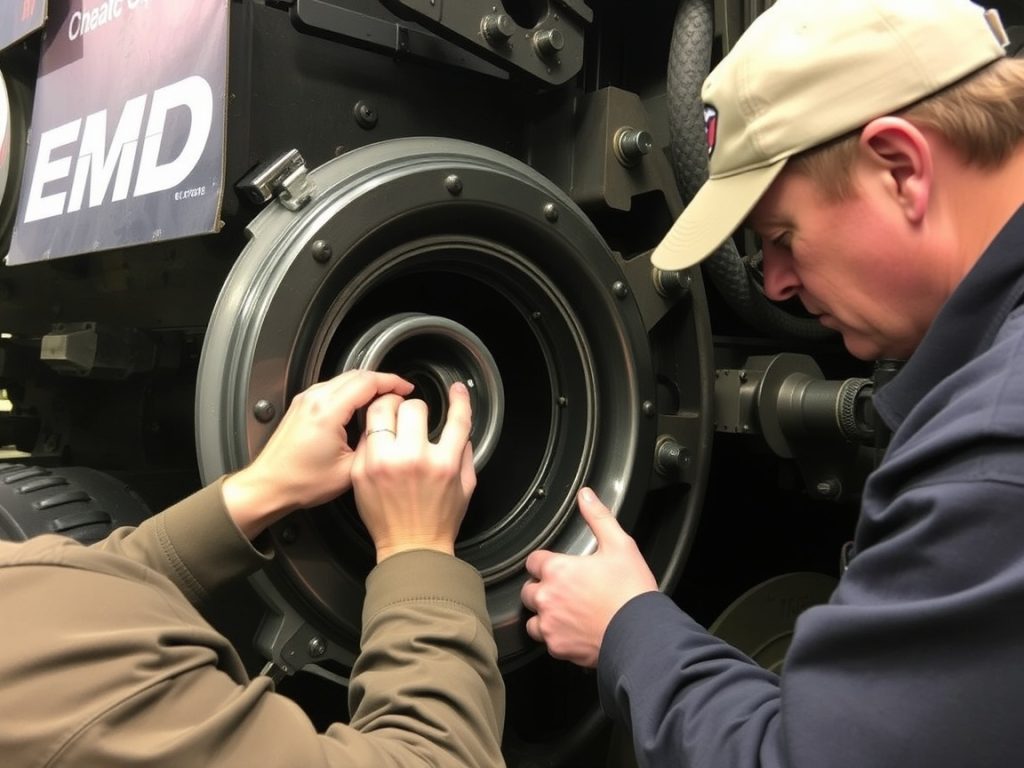
Enhancing Diagnostic Accuracy With Sensor Monitoring and Adaptive Filtering

enhanced brake system diagnostics

Although traditional diagnostic methods often miss subtle performance degradations, modern air brake systems achieve greater accuracy by integrating diverse sensor arrays and adaptive filtering techniques. When you implement sensor integration—employing piezoelectric films, fiberoptics, Hall Effect, and proximity sensors—across NYAB, Wabtec, and TMB-type cylinders, you guarantee precise brake piston travel monitoring. Wireless data relay through On-Board Monitoring and Control Systems (OBMCS) allows real-time visualization and cross-referencing of sensor outputs with brake pipe pressure for validation.

To enhance signal fidelity, apply dynamic filtering to accelerometer and Hall Effect sensor data, isolating brake-related events from ambient noise or track-induced vibrations. Adaptive filtering further refines diagnostics by adjusting thresholds in response to environmental changes. By ensuring that brake pipe leakage remains under 5 lbs/min and main reservoir leaks are maintained below 3 lbs/min, you establish a reliable baseline for sensor data interpretation and can more confidently distinguish between actual faults and normal variations. Predictive analytics leverage these high-resolution data streams, correlating piston travel and air pressure trends to anticipate maintenance needs. As a result, sensor integration and adaptive filtering provide a robust framework for early fault detection and accurate system health assessment.
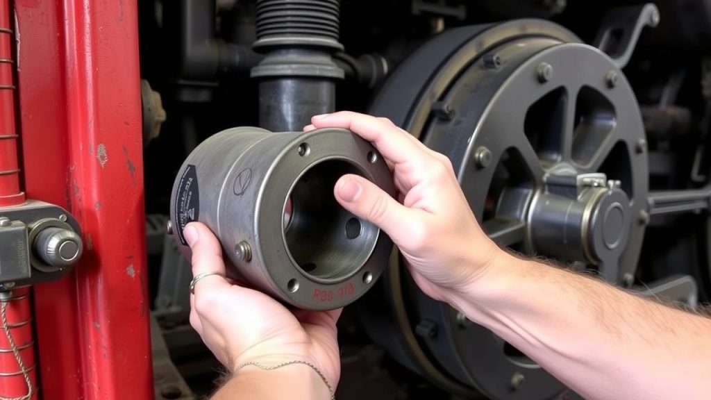
Frequently Asked Questions

How Often Should Air Brake Hoses and Fittings Be Visually Inspected for Wear?

When it comes to hose maintenance and fitting durability, don’t let something slip through the cracks—visually inspect air brake hoses and fittings at least every 368 days as part of your primary maintenance cycle. For advanced systems like CCB-1 or EPIC, you can stretch inspections up to 1,840 days under level three testing. Always check for cuts, swelling, and leaks while the system’s pressurized to make sure components remain roadworthy and safe.

What Are Common Symptoms of a Failing Air Compressor in Locomotives?

When you encounter air compressor failure in locomotives, you’ll notice brake pressure issues such as slow pressure buildup, insufficient gas production, or loss of air output. You might hear unusual noises—grinding or knocking—indicating internal wear. Watch for air leaks, excessive vibrations, or burnt smells from overheating. Persistent drainage or spitting sounds from the air dryer also signal trouble. Always check for faulty pressure switches or blockages causing high air pressure levels.

Can Extreme Cold Weather Affect Brake System Response Times?

Yes, extreme cold weather can greatly impact brake performance and slow brake system response times. You’ll notice increased air leakage, especially at pipe brackets and gaskets, as cold reduces material flexibility. Frozen moisture in hoses or reservoirs restricts airflow, delaying cylinder filling and brake application. Cold steel rails also decrease friction, further reducing effectiveness. To counter these issues, you should monitor system pressure closely and apply brakes periodically to prevent ice buildup.

What Training Is Required for Technicians Performing Brake Diagnostics?

Like a surgeon mastering anatomy, you need brake certification and hands-on diagnostic workshops before performing brake diagnostics. You’ll study 49 CFR 240 standards, pre-trip inspection protocols, and air brake system operations. Training includes conducting Class 1 brake tests, troubleshooting with full-scale mock-ups, and learning model-specific brake controls. You’ll document inspections, handle regulatory compliance, and refresh your skills annually, ensuring you’re equipped to identify, diagnose, and resolve complex locomotive brake issues safely.

How Do You Safely Isolate a Locomotive for Brake System Troubleshooting?

When you perform brake system isolation for troubleshooting, strictly follow safety procedures. First, charge the brake system within 15 psi of the regulating valve setpoint. Notify the crew, then close the appropriate angle cocks to isolate the section. Confirm a full brake release using triple valve or ETD indicators. Secure equipment to prevent drift, and always document the process. After testing, restore continuity by opening angle cocks and verifying air pressure restoration before operation.

How to Replace Locomotive Camshaft Bearings Properly

How to Replace Locomotive Camshaft Bearings Properly

To properly replace locomotive camshaft bearings, start by selecting engine-specific tools and inspecting oil channels and seals. Lubricate new bearings with EP additive, then use precision drivers to insert bearings, aligning oil holes carefully. Apply steady, controlled force—never hammer at an angle—and check for ≤0.004” misalignment. After installation, measure clearances and alignment, verifying everything meets manufacturer specs. If you’re aiming for maximum reliability and bearing longevity, the next steps will guide you through each essential detail.

Key Takeaways

  • Select high-quality, engine-specific tools and bearings, ensuring material and dimensional compatibility with the locomotive engine block.
  • Thoroughly inspect and clean oil channels, replace seals, and apply EP lubricant to all bearing contact surfaces before installation.
  • Carefully align camshaft bearings with oil holes and galleries, using precision tools to achieve ≤0.004” misalignment and ≤0.001” runout.
  • Insert bearings with controlled force using dedicated drivers, avoiding hammering or generic tools that may cause misalignment or damage.
  • After installation, measure clearances and alignment with calibrated instruments, then verify oil flow and proper lubrication during dynamic testing.

Tool Preparation and Selection

tool selection and preparation

Before you start replacing camshaft bearings, select and prepare your tools with precision, as the right equipment guarantees both safety and accuracy. Evaluate tool compatibility by matching your tool kit’s bearing diameter range to the engine specifications—choose mandrels and adapters that accommodate sizes like 1.25″–2.69″ or 0.875″–1.00″. Assess material selection: use aluminum adapters for corrosion resistance or steel mandrels for high-torque jobs.

Expandability matters, so select adjustable mandrels or split driving plugs for flexibility across engine types. Ascertain your set includes core components: driving shafts, expander units, guide cones, and reaction mandrels for controlled, precise bearing installation. Inspect for kit completeness and storage cases to maintain organization. A blow molded case is often included with professional camshaft bearing tools, making storage and transport easier while keeping components protected and organized. Prioritize American-made, durable tools, and source from reputable brands to guarantee safe, accurate camshaft bearing replacement.

Lubrication and Pre-Assembly Steps

camshaft lubrication and inspection

Although it may seem straightforward, proper lubrication and pre-assembly steps are critical to guaranteeing reliable camshaft bearing performance and preventing premature wear. Begin by conducting thorough pre-assembly checks: inspect oil channels in stub shafts, confirm all camshaft galleries are clear, and verify seal integrity at both camshaft ends. Replace all seals and confirm lube oil filters are new to prevent particulate ingress. Use appropriate lubrication techniques—apply an extreme-pressure (EP) additive lubricant to all bearing surfaces and pack bearings to establish a hydrodynamic film at startup.

Verify oil pressure specifications (8–12 psi at idle, 25–29 psi at full load), check scavenging pump operation, and validate relief valve settings for system safety. The main lubricating oil system supplies oil under pressure for cooling and lubrication, which is essential for preventing friction damage during initial engine operation. Align bearings with stub shafts, confirm camshaft concentricity, and check axial clearance per manufacturer tolerances. Finally, secure stub shaft fasteners with threadlocker. These steps, when executed precisely, create ideal conditions for bearing installation and long-term reliability.

Bearing Insertion Techniques

precise bearing installation techniques

Now, you’ll select the correct cam bearing installation tool, making sure it matches your engine’s bore size and configuration. Carefully align each bearing with the oil hole and gallery passage, using visual guides to keep orientation exact. Proper positioning of bearings is crucial to avoid damage and ensure long-term reliability. Apply steady, controlled force with your tool to avoid distorting the bearing surface or damaging the block.

Selecting Proper Insertion Tools

Tool selection plays a critical role in successful camshaft bearing installation, ensuring proper fit, alignment, and minimizing the risk of engine damage. Begin by matching your insertion tool to the bearing diameter—expandable mandrels and universal kits like Lisle’s offer broad tool compatibility for 1.25″ to 2.69″ bearings. For large-bore or GEVO engines, hydraulic ram systems and anchor mandrels are essential for safe, controlled installation.

Use engine-specific adaptors for brands like Cummins and CAT to boost installation efficiency and avoid damage from improper sizing. Adjustable tools with split plugs or collapsing mandrels allow you to adapt to slight bore irregularities, while fixed mandrels provide rigidity for perfect bores. Always check that ancillary components—drive extensions, bar guides, and replacement parts—are in prime condition for safe operation. Expandable mandrels are especially valuable because they instantly adjust to undersize cam bearings, as seen in modern cam bearing tool designs.

Ensuring Precise Bearing Alignment

While precise camshaft bearing alignment is critical to engine reliability, you can achieve it by combining careful preparation with the right insertion techniques. Begin by thoroughly cleaning and inspecting housing bores—any dent or sharp edge can tilt the bearing and throw off alignment tolerances. Use alignment techniques like optical or laser tools to confirm centerline accuracy, and guarantee your insertion driver is perfectly centered.

As you insert each bearing, apply steady, incremental pressure, monitoring for abnormal resistance. Always verify alignment with feeler gauges; your target is ≤0.004” misalignment and ≤0.001” runout. For added accuracy, proper oil hole orientation is essential during cam bearing installation, as misaligned oil holes can lead to low oil pressure and premature bearing wear.

Common PitfallConsequence
Rushed alignmentEngine failure risk
Ignored tolerancesCostly bearing replacement
Misaligned installationDangerous system stress

Never compromise safety—verify every measurement before finalizing assembly.

Preventing Bearing Surface Damage

Achieving precise camshaft bearing alignment lays the groundwork, but you must also protect the bearing surfaces throughout installation to avoid premature wear or catastrophic failure. Always use purpose-designed cam bearing drivers to guarantee straight insertion—never force bearings at an angle, as this can score sensitive bearing materials. Prepare your installation environment by thoroughly cleaning oil gallery holes and applying anti-corrosive lubricant to bearing O-rings.

Proper alignment during installation is essential, as camshaft bearings must be driven into position perfectly straight with oil galley holes aligned to ensure optimal function. Avoid abrasive honing, which risks embedding debris in the bearing surface; precision reaming is safer for tight fits. During insertion, employ controlled hammer blows with a nylon drift, advancing incrementally. Confirm oil feed holes align properly. Test-fit bearings and verify bore diameters before final assembly. These methods protect bearing surfaces, guaranteeing reliable operation and extending service life.

Alignment and Position Verification

camshaft bearing alignment verification

Before seating the camshaft bearings, verify their alignment and position to assure reliable oil delivery and proper engine function. Use alignment strategies that account for block orientation: align the bearing oil feed holes at the 2 o’clock position when the block is upright, or at 8 o’clock if inverted. This guarantees feed holes correspond with oil galleries and 360° oil grooves for ideal hydrodynamic support.

Rely on visible position checks, using alignment marks on both the bearing and block, and confirm proper fit before final installation. Always keep a consistent reference axis—front or rear of the block—to avoid rotational misalignment. Safety demands all oil galleries and bearing surfaces remain clear of debris during these procedures. Distortion during installation can affect the bearing shape and size, so take care to press bearings evenly and avoid introducing stress that could compromise camshaft rotation.

  1. Visually confirm oil feed hole alignment with galleries using reference marks.
  2. Verify block orientation and translate clock positions accordingly for correct installation.
  3. Inspect and clear oil grooves and channels before proceeding to the next installation step.

Hydraulic Press Application Methods

steady pressure for alignment

When you use a hydraulic press to install camshaft bearings, apply steady, controlled pressure in small increments to prevent distortion or misalignment. Always verify that each bearing seats fully and evenly by checking for uniform contact around the circumference. Pause periodically to inspect alignment and adjust force as needed, prioritizing safety and consistent fit throughout the pressing process. Proper hydraulic press application helps maintain the oil clearance critical to camshaft bearing longevity and engine performance.

Controlled Pressure Application Steps

While the hydraulic press provides the necessary force for camshaft bearing installation, precise control and correct tool selection are critical for safe and effective results. Always utilize controlled pressure to prevent bearing distortion and guarantee stability throughout the process. Begin by selecting the correct tool combination from the provided chart for your specific bearing size. Carefully align Tooling B’s chamfer with the bore face, and confirm the bearing oil hole matches the camshaft bore’s oil access. Use Tooling C for bearings three through six to maintain bearing stability and distributed pressure. Monitor the hydraulic pump output for uniform force application and avoid sudden spikes.

For best results, ensure proper alignment during installation, as misalignment of less than .001 can usually be compensated for with adequate clearance but larger misalignments may cause premature bearing wear or engine failure.

  1. Select tool combination per Table 2 for bearing size.
  2. Align oil hole and apply controlled pressure until seating.
  3. Use Tooling C for multi-bearing stability and even load.

Bearing Seating Verification

Although the hydraulic press streamlines camshaft bearing installation, you must verify seating accuracy to affirm reliable engine performance and prevent premature wear. Start by visually inspecting each bearing seat for metal shavings or debris. Use an LS-specific driver and guarantee even force distribution so the bearing aligns concentrically within the housing.

Maintain perpendicularity with the cam bore axis during pressing to avoid eccentric seating, which compromises bearing stability. After pressing, check for proper oil hole alignment and inspect for trapped contaminants. Measure cam journal runout with a dial indicator to confirm concentricity, and use a micrometer to verify bearing ID matches specifications. Documenting all measurements is important to track wear trends over time and ensure ongoing reliability. Test the camshaft for free rotation—any binding may indicate compromised seating accuracy. Always document your measurements for future reference.

Incremental Force Techniques

To achieve precise camshaft bearing removal and installation, incremental force application with a hydraulic press guarantees controlled, consistent load distribution and minimizes the risk of housing or bearing distortion. Begin by setting the hydraulic press to the correct demounting force—up to 63.5 metric tons for railway-specific applications. Use the semi-automatic or fully automatic operation modes to manage the press cycle (2 minutes per cycle), ensuring the ram stroke and extension speed match the bearing size. Always rely on the carriage’s automatic positioning and rack-and-pinion alignment to center the axle journal. This prevents uneven force application and potential damage.

  1. Set adjustable jaws for the specific wheel diameter.
  2. Engage the hydraulic ram gradually, monitoring force application.
  3. Use automated cycle management to maintain incremental force and maximize safety.

Post-Installation Inspection and Testing

post installation inspection protocol

Once you’ve installed new camshaft bearings, it’s critical to conduct a thorough post-installation inspection and testing sequence to guarantee proper function and longevity. Begin your post installation analysis by measuring camshaft journal and bearing bore diameters with calibrated micrometers and bore gauges. Compare recorded clearances to manufacturer specs—any discrepancy over 0.0005″ means immediate attention. Confirm bearing alignment using straightedges, and perform clearance analysis with plastigage or feeler gauges to detect tapering or end-play issues.

Next, inspect cam journals for out-of-round or lobe wear, using micrometers and dial indicators for precision. Mount the camshaft in V-blocks for runout testing; TIR should not exceed 0.002″. Dynamic testing under operational rotation is essential—monitor for abnormal noise, oil film distribution, and proper valve train motion. Always record your findings for traceability and safety.

StepTool UsedSpec/Action
Measure ClearanceMicrometer/Bore G.≤0.0005″ discrepancy
Check AlignmentStraightedgeVisual/Measured conformity
Test RunoutDial Indicator≤0.002″ TIR
Dynamic TestingAccelerometerNoise/vibration monitoring

Maintenance of Tools and Equipment

tool maintenance ensures safety

Proper maintenance of tools and equipment is essential for achieving accurate results and guaranteeing safety during camshaft bearing replacement. Adhering to rigorous tool maintenance and equipment storage protocols minimizes the risk of measurement errors and accidents. Begin each workday by visually inspecting hand tools and machinery for wear, rust, or damage. Calibrate precision instruments such as torque wrenches and force gauges per OEM timetables, documenting all calibration activities for regulatory compliance. Always store tools in climate-controlled, secure environments to prevent corrosion and unauthorized use.

Consistent tool maintenance and careful storage are critical for accuracy and safety when replacing camshaft bearings.

Follow these best practices for effective tool maintenance and equipment storage:

  1. Daily Inspections: Check tools for physical defects, replace worn parts, and guarantee all mechanisms function smoothly.
  2. Scheduled Calibration: Maintain up-to-date calibration according to manufacturer and railroad SMP requirements, especially for critical measurement devices.
  3. Proper Storage: Use labeled, secure storage in dry areas, isolate unused tools, and follow ergonomic handling to reduce fatigue and prevent contamination.

Consistent application of these procedures sustains operational integrity and safety.

Troubleshooting Common Installation Issues

camshaft bearing installation issues

Although camshaft bearing installation may seem straightforward, several common issues can compromise the reliability and longevity of your work. You’ll often encounter bearing distortion from improper bore geometry or use of generic tools. Installation misalignment—especially failing to square bearings in the bore—causes restricted camshaft rotation and premature wear. Always verify bore roundness and alignment with precision gauges before installing new bearings.

Misalignment of oil holes and grooves can starve the camshaft of lubrication, leading to increased friction and bearing failure. Use cam-specific tools to avoid pressing bearings unevenly. Don’t rush: improper chamfering or hammering bearings before they’re fully seated will shed metal shavings and reduce clearances. Finally, always match bearing material and dimensions to the engine block’s requirements.

ProblemPotential Consequence
Out-of-round boresBearing distortion
Misaligned oil holesLubrication failure
Generic installation toolsInstallation misalignment
No chamfer on bore edgesMetal shaving/galling
Material mismatchPremature bearing wear

Frequently Asked Questions

How Often Should Locomotive Camshaft Bearings Be Replaced?

You should determine your locomotive camshaft bearing replacement schedule by following rigorous bearing maintenance protocols and OEM recommendations, typically every 1,000–2,000 engine hours. Don’t ignore warning signs like increased oil consumption, power loss, or visible bearing wear. Always track service intervals and bearing condition in your maintenance logs. Prioritize safety by inspecting for contamination and misalignment, ensuring you replace bearings promptly to prevent catastrophic engine damage and maintain peak locomotive performance.

What Are Signs of Worn Camshaft Bearings During Operation?

When monitoring for bearing wear, you’ll notice operational signs like knocking, chirping, or metallic noises that match engine RPM—these often worsen at startup. Watch for low oil pressure, erratic engine behavior, or excessive crankcase pressure. If you detect overheating, surface discoloration, or rhythmic clattering, act immediately. Always prioritize safety: shut down the engine and inspect the bearings closely, since ignoring these symptoms can lead to catastrophic failure or further component damage.

Can Upgraded Bearings Improve Locomotive Performance or Lifespan?

When you install upgraded bearings, you’ll see clear performance enhancements thanks to advanced bearing technology. You’ll benefit from improved load capacity, better lubrication, and longer lifespan, all of which support high-RPM, high-torque locomotive engines. Always align oil holes precisely and use specialized hydraulic tools to prevent misalignment or bearing damage. Prioritize safety by maintaining anti-contamination protocols and applying correct load-control—these steps maximize both reliability and operational efficiency for your locomotive.

Are OEM and Aftermarket Bearings Interchangeable?

You can’t always interchange OEM and aftermarket bearings due to differences in OEM compatibility and bearing quality. OEM bearings offer precise tolerances, seamless construction, and consistent materials, critical for safety and performance. Aftermarket options may lack exact fitment, have variable quality, or require special tools, risking misalignment or failure. Always check dimensional specs, material composition, and manufacturer guidelines before attempting substitution to guarantee safe, reliable operation and to avoid voiding warranties.

What Safety Precautions Should Be Taken During Bearing Replacement?

Don’t throw caution to the wind—always prioritize safety when replacing bearings. You should wear proper safety gear like gloves and eye protection to guard against debris and lubricant splashes. Ascertain your work environment is clean, well-lit, and free of trip hazards. Isolate all power sources before starting. Use tools as recommended, avoid shortcuts, and follow lockout/tagout procedures. Double-check components for secure handling and alignment to prevent workplace accidents.

Translate »