In the dynamic world of railway operations, the longevity, efficiency, and performance of locomotive fleets are paramount. As diesel-electric locomotives approach pivotal points in their operational lifespan, choosing between complete replacement and targeted repowering or rebuilding emerges as a crucial strategic and financial decision. Modernizing these workhorses not only extends their operational lifespan but also significantly enhances their capabilities, fuel efficiency, and environmental compliance.
Central to the success of these extensive overhaul programs are meticulously engineered components that form the heart of the repowered engine. Among these, EMD part numbers 10634216 and 10634215 stand out as vital elements, representing advancements that are critical for operators looking to maximize the return on their locomotive investments. This article delves into the significance of these specific EMD parts within the broader context of locomotive repowering and rebuild initiatives, exploring their technical merits, integration strategies, and the tangible benefits they deliver.
Introduction to EMD Repowering and Rebuild Programs
The railway industry, a cornerstone of global logistics and transportation, is continuously seeking ways to optimize its asset base. Repowering and rebuilding programs for locomotives have emerged as a primary strategy to achieve this, offering a compelling alternative to the substantial capital outlay required for entirely new fleets. These initiatives are not merely about cosmetic updates; they involve deep-seated technological enhancements aimed at improving performance, reducing operational costs, and meeting stringent environmental regulations.
What Are Locomotive Repowering and Rebuild Initiatives?
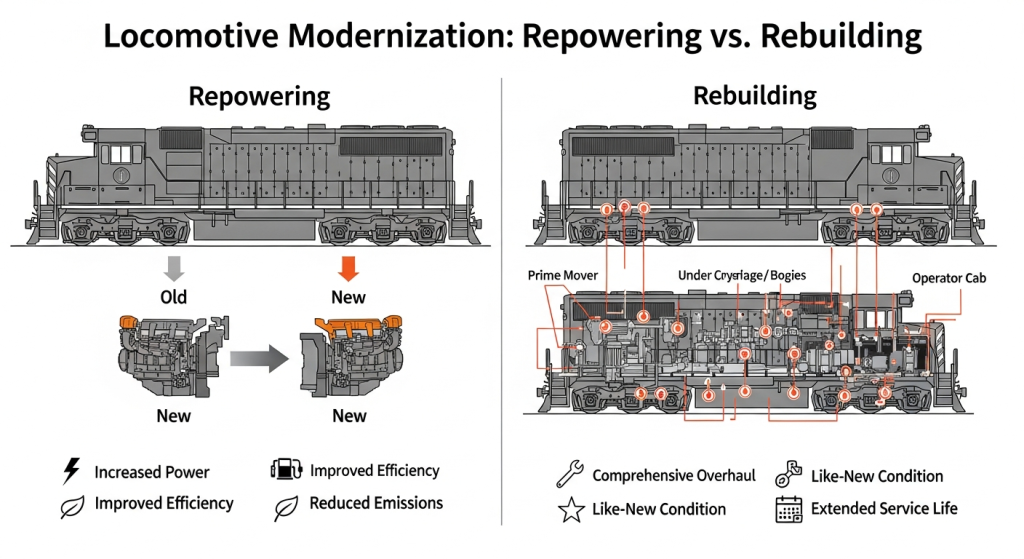
Repowering focuses on replacing the prime mover for performance gains, while rebuilding is a comprehensive overhaul to restore the entire locomotive.
Locomotive repowering involves replacing the existing prime mover and associated systems with a newer, more advanced engine and control technology. This is typically done to increase power output, improve fuel efficiency, reduce emissions, or adopt newer engine architectures. Rebuilding, on the other hand, is a more comprehensive refurbishment process that can include repowering, but also extends to overhauling or replacing virtually every component of the locomotive, from the undercarriage and bogies to the car body and auxiliary systems. The goal is to restore the locomotive to a condition that is functionally equivalent to, or better than, its original manufactured state, thereby extending its service life by many years.
The Evolution of EMD Locomotive Maintenance Strategies
General Motors’ Electro-Motive Division (EMD), now part of Progress Rail, a Caterpillar company, and Wabtec Corporation, has long been a dominant force in locomotive manufacturing. Historically, maintenance strategies often leaned towards reactive repairs, addressing issues as they arose. However, the industry has evolved significantly. Modern maintenance strategies are increasingly proactive and predictive, emphasizing component upgrades and life-extension programs. This shift is driven by the recognition that strategic investments in critical components can prevent costly failures, improve reliability, and unlock new levels of operational performance. EMD’s legacy of robust engineering provides a strong foundation for these modernization efforts, with a continuous stream of innovation ensuring their locomotives can adapt to changing demands.
Why Focus on Specific Parts Like 10634216 and 10634215?
The efficacy of any repowering or rebuild program hinges on the quality and technological advancement of the components used. Certain parts, due to their fundamental role in engine operation and their susceptibility to wear and technological obsolescence, become focal points for upgrades. EMD part numbers 10634216 and 10634215 represent precisely such critical components. These are not merely off-the-shelf replacements; they are engineered solutions designed to deliver superior performance, durability, and efficiency.
Focusing on these specific EMD parts allows operators to target the core of the engine’s power generation and delivery system, ensuring that the benefits of a repower are maximized and that the locomotive can reliably meet the demands of modern rail operations. Their specific design and material composition are key to unlocking enhanced power output and improved sustainability metrics.
Technical Specifications of EMD Part No. 10634216 & 10634215
The engineering excellence embedded within EMD components is a hallmark of the brand. Part numbers 10634216 and 10634215 embody this commitment, featuring advanced design principles and material science that contribute significantly to their performance and longevity within the demanding environment of locomotive operations.
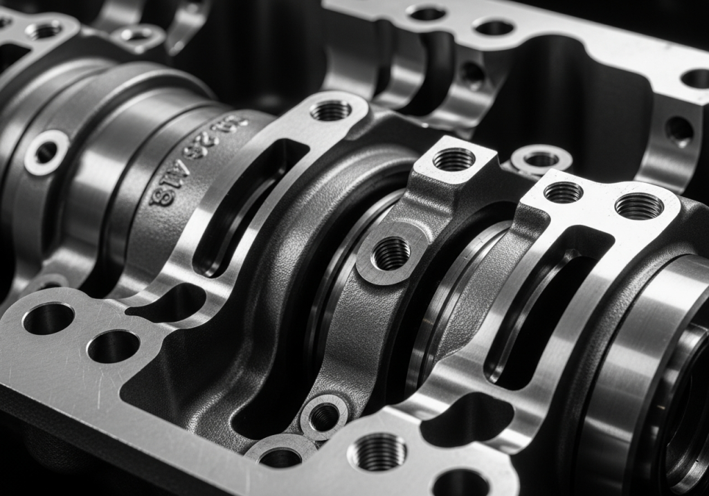
Design and Material Composition
These EMD parts are manufactured to exacting standards, incorporating advanced alloys and precision machining techniques. The design often reflects iterative improvements over previous generations, addressing known stress points and performance limitations. The materials selected are chosen for their exceptional durability, resistance to extreme temperatures and pressures, and optimal thermal conductivity. For example, the use of specialized cast iron alloys or advanced composite materials in critical engine assemblies ensures robust structural integrity and resistance to wear. This meticulous attention to detail in both design and material composition is fundamental to achieving the high performance ratings and extended service life expected from modern EMD components.
Performance Ratings and Compatibility Standards
EMD part numbers 10634216 and 10634215 are engineered to meet or exceed stringent industry performance standards. Their ratings typically encompass parameters such as thermal efficiency, mechanical stress tolerance, and operational lifespan under continuous heavy-duty cycles. Compatibility is a crucial aspect; these parts are designed to integrate seamlessly with specific EMD engine families and associated systems. This ensures that when installed in a repowering project, they contribute to the overall balance and optimized performance of the entire locomotive, rather than creating isolated performance anomalies. Adherence to both internal EMD specifications and broader industry standards guarantees that these components will perform reliably and safely, forming a stable foundation for the modernized locomotive’s operation.
Key Innovations Over Previous Generations
The distinction of parts like 10634216 and 10634215 often lies in their innovative features that set them apart from earlier EMD parts. These innovations can range from enhanced combustion chamber designs that optimize fuel burn for greater efficiency and reduced emissions, to improved lubrication pathways that minimize friction and wear.
Advanced turbocharger system integration, refined fuel injector technology, and more robust piston and cylinder liner designs are common areas of development. For instance, advancements in fuel injectors can lead to finer atomization of fuel, resulting in more complete combustion. Similarly, improved turbocharger designs can provide more efficient air management, boosting power output while maintaining fuel economy. These incremental yet significant technological leaps are precisely what enable modern repowering initiatives to deliver substantial improvements over the original specifications of older locomotives.
Compatibility with EMD Locomotive Models
The successful integration of critical components like EMD 10634216 and 10634215 into a repowering project is highly dependent on their compatibility with specific EMD locomotive models and their existing engine configurations. This ensures a smooth transition and maximum performance benefits.
Supported Engine Blocks and Prime Movers
These specific EMD parts are typically designed for compatibility with a range of EMD engine families, most notably the advanced versions of the 710 series and potentially components designed for the larger 824 prime mover found in models like the SD90MAC-H. The precise compatibility will depend on the exact sub-model and configuration of the engine being rebuilt. For example, in the context of repowering an older EMD locomotive, these components would be selected to match the bore, stroke, and overall architecture of the intended replacement or upgraded engine block, ensuring a perfect mechanical and operational fit. This careful matching is essential for preventing compatibility issues and achieving optimal performance from the modernized engine.
Integration in Popular Freight and Passenger Locos
The EMD SD70 series, a workhorse in freight and passenger service, is a prime candidate for repowering and modernization. Similarly, the SD90MAC-H, known for its high horsepower output, can benefit significantly from upgrades involving components like 10634216 and 10634215. When integrated into these popular EMD locomotive models, these advanced parts can contribute to enhanced tractive effort, improved acceleration, and greater fuel efficiency. This is particularly important for freight operations where sustained power is crucial for hauling heavy loads, and for passenger services where punctuality and operational efficiency are key. The benefits extend to the overall reliability of traction motor refurbishment, as a more powerful and efficient prime mover can sometimes allow for more optimized operation of traction motors.
Retrofit Challenges and Solutions
Integrating newer components into older locomotive frames can present challenges. These can include modifications required for engine mounts, exhaust systems, cooling systems, and electrical connections. However, these challenges are well-understood within the industry. Solutions often involve custom-engineered adapter plates, upgraded cooling system maintenance protocols to handle increased thermal loads, and recalibration of the locomotive’s overall electrical systems. Reputable manufacturers and rebuilders, such as those associated with Progress Rail and Wabtec, have developed extensive engineering knowledge and standardized procedures to address these retrofit complexities. Utilizing OEM parts or high-quality aftermarket components for 10634216 and 10634215, sourced from trusted suppliers, ensures that these parts are manufactured to specifications that facilitate easier integration and reliable long-term operation.
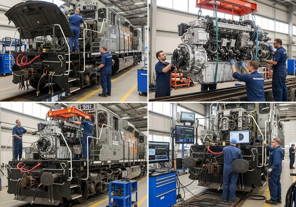
Step-by-Step Integration into Repowering Projects
The successful integration of critical components like EMD 10634216 and 10634215 into a locomotive repowering project is a systematic process that demands careful planning, precise execution, and thorough verification. This methodical approach ensures that the modernized locomotive achieves its full potential.
Pre-Installation Assessment and Planning
The initial phase involves a comprehensive assessment of the existing locomotive. This includes a detailed inspection of the locomotive frame for any structural integrity issues requiring locomotive frame repair, and a thorough diagnostic of all major systems, including the electrical systems, cooling system maintenance needs, and the condition of traction motors.
Compatibility checks for the selected EMD parts against the intended engine block are paramount. Engineering teams will define the scope of work, identify any necessary modifications, and develop a detailed project timeline. Procurement of all necessary EMD parts, including high-quality engine overhaul kits and specific components like 10634216 and 10634215, is finalized at this stage, ensuring both OEM parts and reputable aftermarket components are sourced with quality as the primary criterion.
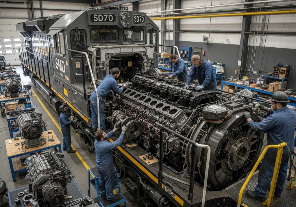
Disassembly and Power Assembly Replacement
Once planning is complete, the locomotive undergoes disassembly. This involves carefully removing the old prime mover and associated auxiliary systems. The focus then shifts to the installation of the new power assembly. This stage is where EMD 10634216 and 10634215, often integral parts of an engine overhaul kit, are installed with meticulous attention to detail. This includes precise torque specifications for all fasteners, correct alignment of rotating components, and proper installation of seals and gaskets to prevent leaks. Attention is also paid to related systems that are often upgraded concurrently, such as the fuel injectors and the turbocharger system, to ensure they are compatible with the new engine configuration and are performing optimally.
Post-Installation Testing and Calibration
Following the physical installation, a rigorous testing and calibration phase is initiated. This begins with initial startup procedures, closely monitoring engine parameters for any anomalies. Extensive diagnostic tests are performed to verify the performance of the new EMD parts and the integrated systems. This includes load testing to assess the locomotive’s power output, fuel consumption, and thermal management under simulated operating conditions.
The electrical systems are checked for correct voltage regulation and load distribution. Calibration of engine control units (ECUs) ensures that the engine operates at peak efficiency and meets emissions standards. This comprehensive testing and calibration process is crucial to validating the success of the repowering effort and ensuring the locomotive is ready for service, delivering the promised reliability and performance gains.
Benefits and ROI of Using These Parts in Rebuilds
The strategic incorporation of advanced components like EMD 10634216 and 10634215 into locomotive repowering projects yields significant, quantifiable benefits, translating into a compelling return on investment (ROI) for rail operators.
Fuel Efficiency and Emissions Reductions
Modern EMD components are designed with efficiency as a core principle. The advanced combustion technology, improved fuel injection, and optimized airflow management facilitated by parts like 10634216 and 10634215 contribute to substantial fuel efficiency improvements, often in the range of 15-20% compared to older models [Intel Market Research, August 2025]. This reduction in fuel consumption directly translates to lower operating costs. Furthermore, more efficient combustion leads to a significant decrease in harmful emissions. While rail transportation is already a highly sustainable mode, accounting for only around 1% of transport emissions globally [UIC Global Sustainability Report, November 2025] and being about four times more fuel-efficient than long-haul trucking [Association of American Railroads, November 2023], further reductions are critical for environmental stewardship and regulatory compliance.
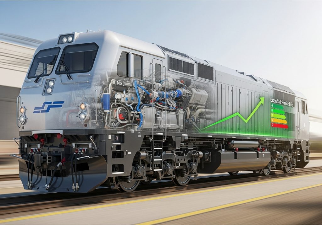
Extended Service Life and Reliability Gains
By replacing worn or outdated components with new, high-performance EMD parts engineered for durability, the overall service life of a locomotive can be significantly extended. This means locomotives can remain in active service for an additional 10 to 20 years, deferring the need for costly new fleet acquisitions. The enhanced reliability translates into reduced unplanned downtime, which is a major operational cost for any railroad. Improved Mean Time Between Failures (MTBF) due to the robust nature of these components means more time spent in revenue service and less time in the workshop, directly impacting operational efficiency and profitability.
Cost Savings Compared to New Locomotives
The global locomotive remanufacturing market, valued at US$ 8.702 billion in 2025 and projected to reach US$ 11.890 billion by 2032, underscores the economic attractiveness of rebuilds [QYResearch via openPR.com, March 2026]. Repowering and rebuilding a locomotive using critical components like EMD 10634216 and 10634215 is typically far less expensive than purchasing a new locomotive. While Class I freight railroads reinvested $26.8 billion into their systems in 2023 for modernization and performance [Association of American Railroads, 2024], a significant portion of this investment can be strategically allocated to high-value rebuilds. The total cost of ownership is reduced through lower upfront capital expenditure, extended asset life, and decreased operational and maintenance costs, making repowering a highly attractive financial proposition.
Real-World Case Studies and Best Practices
The theoretical benefits of using advanced components in locomotive repowering are consistently validated by practical applications across the global railway industry. These real-world examples, often involving major players like Progress Rail and Wabtec, highlight successful implementations and provide valuable lessons learned.

Successful Repowers by Major Railroads
Numerous Class I railroads and other large operators have embarked on extensive repowering programs, often targeting fleets of SD70 series locomotives or similar heavy-haul EMDs. These projects frequently involve the complete overhaul of engines, incorporating the latest EMD parts to achieve modern performance standards. Success is typically measured by dramatic improvements in fuel efficiency, compliance with stringent emissions regulations, and a significant reduction in unscheduled maintenance events. For instance, a repowering program might see locomotives that were previously struggling to meet operational demands being revitalized to outperform their original specifications, enabling them to handle heavier loads more efficiently or operate at higher average speeds.
Lessons from Field Implementations
Field experience has shown that while the core components like 10634216 and 10634215 are crucial, a holistic approach yields the best results. This includes paying close attention to ancillary systems. For example, repowering often presents the ideal opportunity for comprehensive brake system upgrades to match the increased power and performance capabilities of the new engine. Similarly, ensuring the cooling system maintenance is up to par is vital to prevent overheating and ensure the longevity of the new engine components. Lessons also emphasize the importance of selecting reputable suppliers for both OEM parts and high-quality aftermarket components, as consistency in manufacturing and material integrity is key to long-term reliability.
Future Trends and Emerging Upgrades
The trend towards locomotive modernization is set to continue, driven by demands for greater sustainability and operational efficiency. While the global locomotive market is projected for substantial growth, reaching USD 45.35 billion by 2033 [Mordor Intelligence, March 2026], the focus will increasingly be on optimizing existing assets. Future trends include further integration of advanced digital technologies for predictive maintenance, improvements in hybrid diesel-electric powertrains, and continued refinements in combustion efficiency. As regions like India push towards electrification targets [IEA, July 2023], the importance of highly efficient and clean diesel repowering remains critical for many other markets and applications where full electrification is not yet feasible or economical. The ongoing development of EMD parts will undoubtedly reflect these evolving industry needs.
Conclusion: Optimizing Your Locomotive Fleet with EMD Parts
The strategic decision to repower or rebuild older locomotives represents a forward-thinking approach to fleet management, offering substantial operational and financial advantages. At the core of these transformative projects are critical EMD components, such as part numbers 10634216 and 10634215. These are not merely spare parts; they are engineered solutions embodying the latest advancements in diesel engine technology, designed to enhance performance, improve efficiency, and ensure long-term reliability.
Key Takeaways for Rail Operators
Investing in repowering programs that utilize advanced EMD parts like 10634216 and 10634215 offers a clear path to optimizing locomotive fleets. The benefits are multifaceted: significant improvements in fuel efficiency and reductions in emissions contribute to both economic savings and environmental responsibility. The enhanced durability and reliability of these components translate into extended service life and reduced operational downtime, maximizing asset utilization. Crucially, repowering provides a cost-effective alternative to acquiring new locomotives, delivering a compelling return on investment through a lower total cost of ownership.
Next Steps for Repowering Your Fleet
For rail operators considering modernization, the journey begins with a thorough assessment of their current fleet’s condition and operational requirements. Engaging with experienced EMD service providers and component suppliers is crucial to identify the most suitable repowering strategies and select the right EMD parts, including essential components like 10634216 and 10634215. A detailed project plan, encompassing everything from initial diagnostics and potential locomotive frame repair to the precise integration of new power assemblies and comprehensive post-installation testing, is vital for success. Considering ancillary system upgrades, such as brake system upgrades and cooling system maintenance, alongside the core engine work will ensure a holistic improvement.
Resources for Further Reading
To gain a deeper understanding of locomotive repowering, EMD component technologies, and the broader trends shaping the rail industry, consult resources from leading organizations and manufacturers. Industry publications, technical white papers from companies like Progress Rail and Wabtec, and reports from bodies such as the UIC (International Union of Railways) and the Association of American Railroads offer valuable insights into the evolving landscape of locomotive maintenance and modernization. Exploring these resources will empower operators to make informed decisions that drive efficiency, sustainability, and profitability across their locomotive fleets.