EMD 567 vs 645: Complete Technical Comparison Guide for Locomotive Engine Specialists

EMD 567 vs 645: Complete Technical Comparison Guide for Locomotive Engine Specialists

Understanding the Core Challenge: Choosing Between EMD 567 and 645 Components

Fleet maintenance managers and locomotive engineers frequently face critical decisions when managing aging or transitioning locomotive fleets. The distinction between EMD 567 and 645 engine platforms impacts component sourcing, maintenance protocols, operational performance, and long-term capital expenditure planning.

Many professionals encounter confusion regarding component interchangeability, performance implications, and upgrade pathways, leading to costly errors in procurement and operational inefficiencies. The complexity intensifies when dealing with aging 567 equipment while newer 645-platform locomotives operate within the same fleet, requiring dual-sourcing expertise and comprehensive understanding of both platforms’ technical requirements.

Common Problems Faced by EMD 567 / 645 Locomotive Professionals:

  • Uncertainty about which components are directly interchangeable between 567 and 645 platforms, leading to incorrect part ordering and extended downtime
  • Limited availability of 567-series components, forcing difficult decisions between expensive sourcing solutions and premature fleet retirement
  • Confusion regarding power assembly upgrade feasibility and required modifications for 567-to-645 conversions
  • Difficulty identifying performance differences that justify capital investment in 645-platform technology
  • Lack of clear guidance on component specifications and compatibility verification procedures before purchasing
  • Uncertainty about maintenance interval differences and component wear pattern variations between engine families
  • Complexity in calculating total cost of ownership when comparing repair options across different engine platforms
  • Challenges in understanding technical specifications and their practical operational implications for specific locomotive duties
  • Inadequate information about bearing journal box maintenance distinctions affecting long-term equipment reliability
  • Confusion about fuel injection system differences and their impact on fuel economy and emissions compliance

Comprehensive EMD 567 and EMD 645 Engine Specifications

Comprehensive EMD 567 and EMD 645 Engine Specifications

Understanding the fundamental technical specifications of both engine families provides essential context for all downstream maintenance and component decisions. The EMD 567 engine designation refers to its total displacement of 567 cubic inches, representing the cumulative piston displacement across all cylinders. This engine platform emerged from earlier two-cycle technology and became the workhorse of American diesel-electric locomotives throughout the mid-twentieth century. The EMD 645 engine, by contrast, represents a modernized successor platform with 645 cubic inches total displacement, reflecting larger bore dimensions while maintaining identical stroke length to its predecessor.

SpecificationEMD 567EMD 645
Bore Diameter8.5 inches9 1/16 inches
Stroke Length10 inches10 inches
Total Displacement567 cubic inches645 cubic inches
Compression Ratio (Standard)16:1 (later 567D variants)14.5:1
Maximum RPM800-900 RPM900-950 RPM
Base Horsepower (Turbocharged)Up to 2,000 HPUp to 3,600 HP (V-20)
Fuel SystemMechanical unit injectorsMechanical unit injectors
Aspiration OptionsRoots blower or turbochargerTurbocharger or turbocharged variants
Production Era1940s-1990s1960s-present

The bore increase from 8.5 inches to 9 1/16 inches represents the primary dimensional change driving the performance distinction between these platforms. While the stroke remains constant at 10 inches, the larger bore enables greater piston displacement per cylinder, delivering approximately 14 percent increased displacement and corresponding power output advantages.

This seemingly modest dimensional difference cascades throughout engine architecture, affecting bearing loads, component strength requirements, and cooling system capacity. The EMD 645 engine’s lower compression ratio of 14.5:1 compared to later 567D variants at 16:1 reflects advanced combustion chamber design and improved fuel injection timing capabilities, offsetting power loss while improving reliability and reducing mechanical stress on internal components.

Power Assembly Architecture: EMD 567 vs 645 Comparison

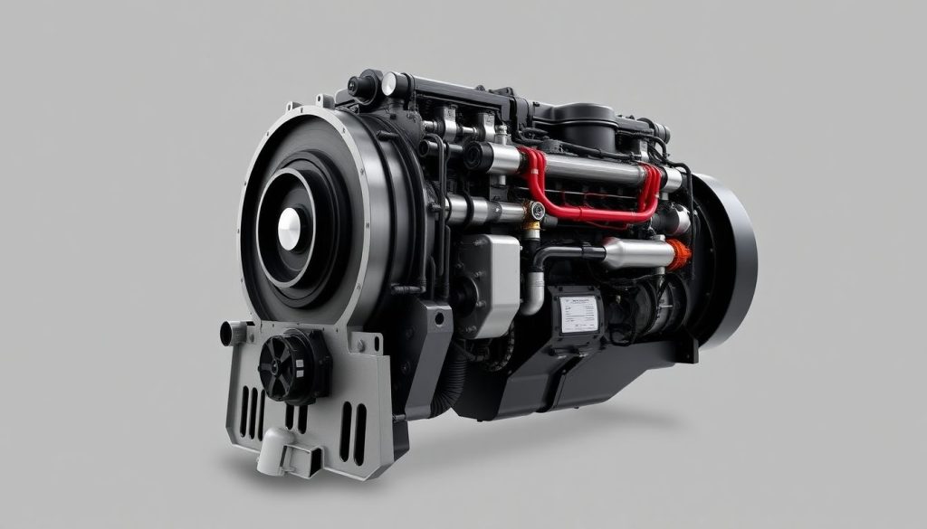
The power assembly represents the heart of locomotive diesel engines, encompassing pistons, connecting rods, crankshaft, and associated bearings that convert fuel combustion energy into mechanical power. Understanding power assembly differences proves critical for fleet managers evaluating upgrade options or managing component availability challenges. The 567 versus 645 power assembly comparison directly influences maintenance decisions, component replacement costs, and retrofit viability assessments.

Bore and Stroke Implications for Power Assembly Design

The EMD 645 bore and stroke configuration requires fundamentally different piston architecture compared to 567 engines. Larger 645 pistons, approximately 9 1/16 inches in diameter, demand enhanced ring groove design, improved skirt configuration, and upgraded material specifications to manage increased combustion pressures and thermal loads.

The identical 10-inch stroke length suggests similar rod-to-stroke ratios, yet the 645’s increased piston mass necessitates stronger connecting rod forgings and enhanced journal bearing materials to accommodate higher reciprocating weight and inertial forces. Premium pistons in 645 assemblies typically incorporate tin-plated skirts that enhance lubrication effectiveness, reducing scuffing tendencies and extending component lifespan compared to earlier 567 designs.

Crankshaft Counterweight Considerations

One of the most critical technical distinctions between 567 and 645 power assemblies involves EMD engine crankshaft counterweights. The 645 crankshaft incorporates enhanced counterweight design reflecting the larger piston mass and resulting unbalanced forces during operation. Camshaft counterweights also require specific adjustment when retrofitting 645 power assemblies into 567 crankcases, a reality that separates knowledgeable technicians from those unfamiliar with upgrade complexity.

The counterweight modifications ensure proper dynamic balance throughout the engine’s operating RPM range, preventing destructive vibration and premature bearing wear. This technical requirement explains why many 567-to-645 conversions require consultation with specialized engineers before implementation, as incorrect counterweight installation can result in catastrophic bearing failures and unscheduled fleet downtime.


Performance Differentiation: Horsepower Advantages and Operational Characteristics

Performance Differentiation: Horsepower Advantages and Operational Characteristics

Fleet operators evaluating 645 engine horsepower advantages must understand the multifaceted performance distinctions separating these platforms. The 645 series engine delivers dramatically superior power output, with turbocharged V-20 configurations producing up to 3,600 horsepower compared to 567 engines rarely exceeding 2,000 horsepower even with turbocharging. This horsepower advantage directly translates to improved grade-climbing capability, faster acceleration, and enhanced tonnage capacity for freight operations—factors that influence line-haul service viability and operational economics.

RPM and Power Delivery Profiles

EMD 567 engine RPM specifications typically range from 800 to 900 RPM maximum, while 645 engines operate reliably at 900 to 950 RPM. This modest RPM differential, combined with increased displacement, generates the substantial power advantages distinguishing these platforms.

The lower 567 RPM ceiling reflects conservative engineering practices and mechanical limitations inherent in earlier design philosophy, while 645 engines benefit from advanced bearing technology, improved combustion control, and refined crankshaft dynamics enabling higher sustained operating speeds.

Fleet operations managers should recognize that power delivery profiles differ significantly, with 645 engines providing flatter power curves across broader operating ranges, enabling more consistent performance during variable-demand service such as switching operations or congested rail yards.

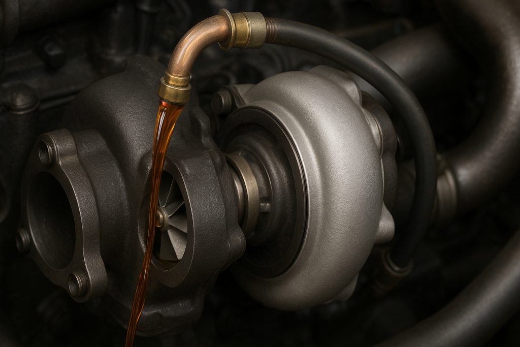
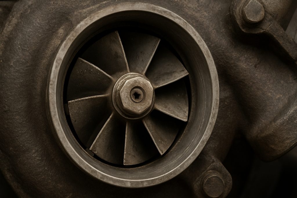
Aspiration Technology: Turbocharger versus Roots Blower

The turbocharger versus Roots blower comparison illuminates fundamental advancement in locomotive technology between 567 and 645 platforms. Many 567 engines operate with Roots blower forced induction, a mechanically simple system where the blower belt-drives directly from the crankshaft. This system delivers consistent air pressure but requires mechanical energy extraction from engine output, reducing net horsepower available for rail movement.

Turbocharged 645 engines recover exhaust energy otherwise wasted, compressing intake air with zero mechanical parasitic loss. Turbocharged 645 engines can deliver 50 percent horsepower increases compared to their naturally-aspirated or Roots-blown counterparts, fundamentally altering locomotive performance characteristics and economic viability for demanding service assignments.


Component Interchangeability and Compatibility Analysis

Fleet maintenance professionals frequently encounter situations requiring component interchangeability decisions. Understanding which components can transfer between platforms and which require platform-specific sourcing determines procurement strategy, inventory management, and equipment availability during critical maintenance windows.

EMD Cylinder Liner Compatibility and Modifications

EMD Cylinder Liner Compatibility and Modifications

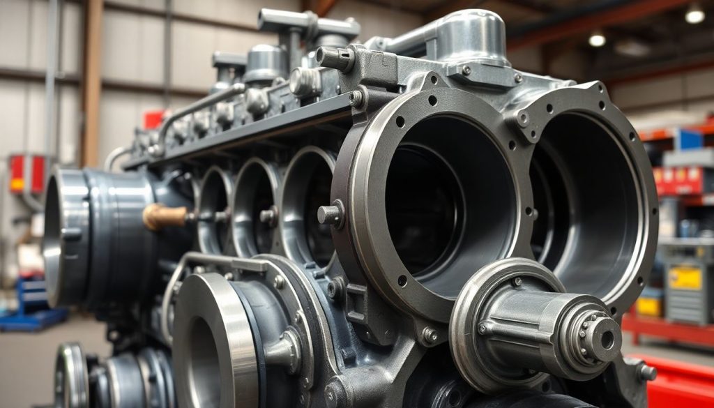
EMD cylinder liner compatibility between 567 and 645 platforms represents a nuanced technical question with significant maintenance implications. While 567C and 567D engines can physically accept 645-series cylinder liners with appropriate modifications, this compatibility requires careful engineering validation.

The larger bore diameter of 645 liners necessitates cylinder block modifications or specialized adapter rings when retrofitting into 567 crankcases, adding expense and complexity that may offset anticipated benefits. Conversely, 645 engines cannot economically utilize 567 liners, as the dimensional mismatch prevents proper sealing and exposes cylinder walls to excessive clearances. Fleet operators contemplating liner retrofits should engage specialized technical resources to validate specific application requirements, as improper liner installation can result in catastrophic failures including crankcase explosions and catastrophic equipment damage.

Locomotive Bearing Journal Box EMD Specifications

Locomotive bearing journal box specifications differ between 567 and 645 engines, though many bearing types cross-reference between platforms with proper verification. Main and rod bearings in 645 engines typically feature enhanced load capacity compared to 567 applications, reflecting the higher reciprocating masses and combustion pressures inherent in the larger-bore platform.

Bearing clearance specifications, lubrication requirements, and replacement intervals may vary between engines, making blind part substitution inadvisable. Experienced fleet maintenance departments maintain comprehensive bearing specification matrices for each engine family represented in their locomotive fleet, enabling rapid identification and procurement of correct replacement components without ambiguity or installation delays.

Fuel Injection System Differences

EMD fuel injection system differences between 567 and 645 platforms reflect evolutionary refinement in combustion control and emissions management. Both platforms utilize mechanical unit injectors, eliminating the electronic fuel control complexity introduced in later EMD models. However, 645 fuel injectors generally feature improved spray patterns, refined injection timing, and enhanced durability compared to 567 counterparts.

The mechanical unit injector design remaining consistent across both platforms means some injector types may cross-reference, though specification verification remains essential before assuming interchangeability. Fuel system pressure specifications typically range from 9,000 to 12,000 PSI in 567 engines, while 645 engines operate at comparable pressures, though specific nozzle designs and needle lift characteristics may vary between applications.


Upgrade Pathways: 645 Power Assembly Upgrade 567 Strategy

Many fleet operators face decisions regarding 645 power assembly upgrade 567 engines as a cost-effective modernization strategy. This upgrade pathway offers compelling advantages compared to complete locomotive retirement, enabling mid-life fleet revitalization with improved performance, enhanced reliability, and extended asset lifespan. Successful implementation requires comprehensive engineering analysis, meticulous component selection, and precise installation procedures ensuring proper mechanical integration.

Technical Requirements and Feasibility Assessment

Technical Requirements and Feasibility Assessment

Retrofitting 645 power assemblies into 567C and later crankcases represents a technically feasible upgrade path successfully implemented thousands of times across North American railroads. The retrofit process capitalizes on the identical stroke length and compatible block architecture, enabling power assembly substitution with acceptable engineering simplicity.

However, camshaft counterweight adjustment emerges as a critical requirement—failure to properly address this modification during installation results in severe vibration, bearing distress, and premature component failure. The retrofit also necessitates fuel system validation, fuel injection advance timing verification, and performance testing under actual operating conditions to ensure reliability and acceptable emissions compliance.

Retrofit Implementation Procedure

Successful 645 power assembly retrofits typically follow methodical procedures beginning with comprehensive teardown inspection of existing 567 equipment. Crankcases undergo careful cleaning, dimensional verification, and defect assessment before 645 component integration. New gasket sets, bearing shells, and carefully verified fasteners ensure leak-free assembly.

Camshaft counterweight modification proceeds under direct supervision of experienced technicians familiar with the specific adjustment requirements. Performance testing following assembly includes running-in procedures under controlled conditions, fuel consumption verification, and emissions testing to confirm acceptable operation across intended service parameters. Many fleet operators engage specialized remanufacturing facilities for this work, leveraging their expertise and specialized equipment while maintaining warranty protection and compliance documentation.


Performance Comparison Table and Selection Guidelines

Operational FactorEMD 567EMD 645Selection Implication
Horsepower RangeUp to 2,000 HPUp to 3,600 HP645 for demanding freight; 567 for switching
Grade ClimbingModerate capacitySuperior capability645 for mountain/congested routes
Fuel Efficiency6-8 MPG equivalent7-9 MPG equivalent645 marginally superior
Component AvailabilityLimited, aging stockExtensive inventory645 preferable for long-term reliability
Maintenance ComplexityModerateHigher (advanced systems)Consider technician expertise availability
Retrofit FeasibilityN/A (older design)Upgrade 567 to 645 possible645 retrofit extends equipment life
Initial Acquisition CostLower (used equipment)HigherBudget constraints vs. long-term value
Service Life Potential20-30 years30+ years645 offers extended economic viability

Maintenance Distinctions and Diesel Engine Piston Ring Wear Patterns

Maintenance protocols diverge between 567 and 645 engines based on design philosophy and component durability characteristics. Understanding these distinctions enables fleet maintenance directors to establish appropriate service intervals, inventory spare components strategically, and predict component failures before catastrophic consequences develop.

Piston Ring Wear Characteristics

Diesel engine piston ring wear patterns differ between 567 and 645 platforms, reflecting design refinements and material improvements in the 645-generation components. Modern 645 ring sets incorporate enhanced chrome plating, refined ring profile geometry, and improved material composition extending service life compared to 567 counterparts.

Low-oil-consumption ring sets in 645 engines produce less smoke and lower particulates, benefiting fleet operators operating in emissions-sensitive regions. Ring groove wear progression typically manifests earlier in 567 engines, necessitating more frequent overhauls and ring replacement compared to 645 engines with comparable service hours.

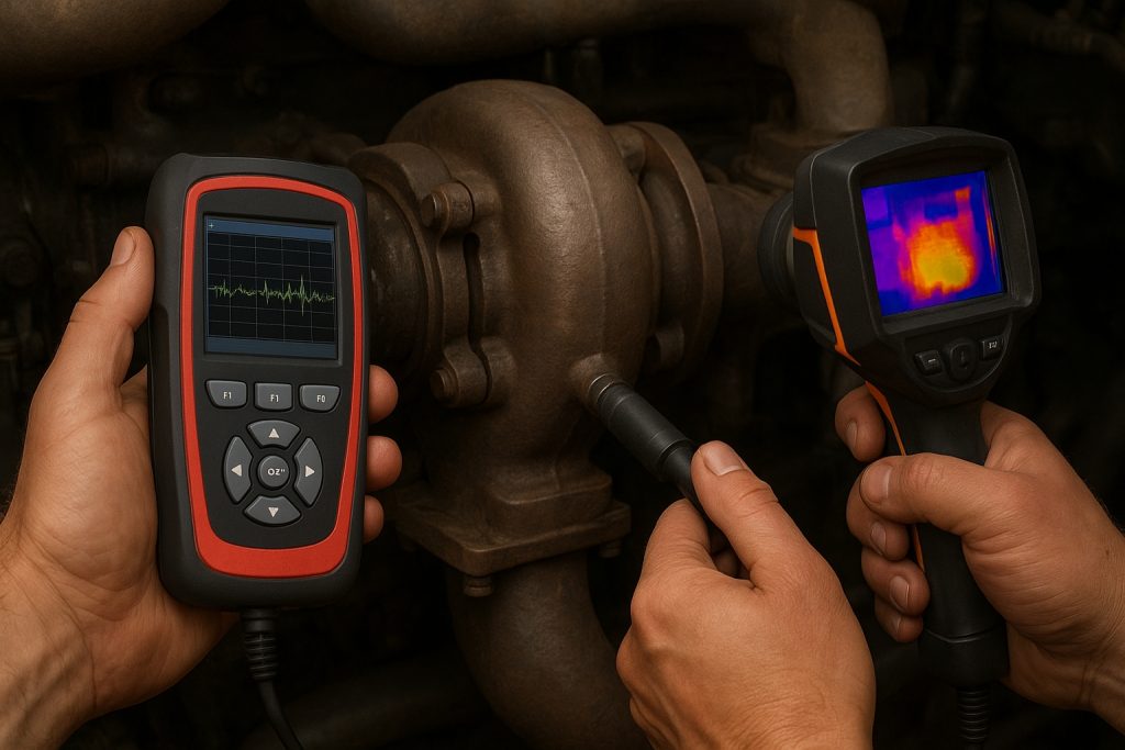
Oil Analysis and Condition Monitoring

Proactive oil analysis programs reveal operational distinctions between engine families. 567 engines typically exhibit higher iron content in used oil, reflecting accelerated bearing wear and component stress compared to 645 engines under similar service conditions. Fuel dilution rates differ between engine families, with 567 engines demonstrating greater fuel-oil mixing particularly in cold weather operation. These analytical findings inform maintenance decisions, spare parts inventory, and rebuild interval planning specific to each engine family represented in fleet operations.

Scheduled Maintenance Intervals

Maintenance TaskEMD 567EMD 645
Oil ChangesEvery 250-300 hoursEvery 300-400 hours
Fuel Filter ReplacementEvery 400 hoursEvery 500 hours
Air Filter ServiceEvery 250 hoursEvery 300 hours
Bearing InspectionEvery 1,000 hoursEvery 1,500 hours
Major Overhaul20,000-25,000 hours30,000-40,000 hours

Component Sourcing and Availability Considerations

567 Power Assembly Availability Challenges

The 567 power assembly availability constraint represents the primary driver pushing fleet operators toward 645 platform adoption or retrofitting. Original equipment manufacturer production of 567 power assemblies ceased years ago, forcing operators dependent on aging 567 locomotives toward limited remanufactured sources or costly custom manufacturing. This scarcity directly impacts fleet maintenance economics, potentially making component costs prohibitive when sudden failures require emergency replacement. Strategic fleet operators maintain surplus 567 power assemblies in reserve for critical locomotives, hedging against supply disruptions and sudden availability challenges.

645 Power Assembly Sourcing Options

645 Power Assembly Sourcing Options

The 645 platform’s continued production ensures robust component availability through multiple distribution channels. Fleet operators can source 645 components from extensive inventory, benefit from competitive pricing reflecting manufacturing scale economies, and avoid extended lead times characteristic of 567 sourcing. This availability advantage translates to reduced fleet downtime, more predictable maintenance budgeting, and enhanced operational reliability—factors justifying capital investment in 645-platform modernization.


Practical Implementation: When to Retrofit, When to Replace

Fleet management decisions regarding 645 power assembly upgrade 567 versus complete locomotive retirement demand comprehensive economic analysis. Retrofit viability depends on locomotive frame condition, electrical system compatibility, and anticipated remaining service life. Well-maintained 567 frames less than twenty years old typically justify retrofit investment, while severely deteriorated or antiquated frames may justify complete replacement despite higher capital expenditure.

Retrofit Justification Criteria:

  • Locomotive frame structural integrity confirmed through comprehensive inspection
  • Electrical systems compatible with 645-era control systems or economically upgradeable
  • Anticipated remaining service life exceeding 10-15 years supporting retrofit amortization
  • Fuel system capable of supporting 645 injection system requirements
  • Cooling system capacity adequate for 645 engine thermal output
  • Component lead times acceptable for planned retrofit scheduling

Conclusion: Strategic Component Selection for Fleet Operations

EMD 567 and EMD 645 platforms represent distinct technological generations within locomotive diesel engine families, each offering specific advantages reflecting their design era and intended applications. Fleet maintenance professionals equipped with comprehensive understanding of EMD 567 engine specifications, EMD 645 engine specifications, and detailed EMD 567 vs 645 comparison frameworks can optimize component procurement, extend equipment lifespan, and minimize unscheduled downtime through informed decision-making.

The transition from 567 to 645 platforms reflects broader industry evolution toward enhanced efficiency, improved reliability, and superior environmental performance. While 567 engines continue serving satisfactorily in many applications, emerging component availability constraints and superior 645 platform economics increasingly favor modernization investments. Fleet operators maintaining balanced portfolios of both engine families require sophisticated maintenance capabilities, comprehensive spare parts inventories, and access to qualified technical resources familiar with both platforms’ nuances.

Experienced fleet managers recognize that successful locomotive operations depend fundamentally on informed component specification, precise technical knowledge, and access to reliable sourcing partnerships. Whether managing aging 567 equipment, leveraging 645-platform capabilities, or executing strategic retrofit upgrades, maintaining detailed component specifications and performance documentation enables data-driven decisions optimizing long-term fleet economics and operational reliability.

For fleet maintenance professionals seeking verified component specifications, technical consultation, or reliable sourcing partnerships supporting both 567 and 645 platforms, engaging experienced suppliers offering comprehensive technical expertise and verified component quality ensures maintenance programs remain aligned with operational objectives and budget constraints. Strategic sourcing partnerships, armed with detailed technical knowledge and proven component reliability, transform locomotive maintenance from reactive problem-solving into proactive optimization supporting fleet modernization and extended equipment lifespan.

GE 7FDL Turbocharger: Complete Maintenance Schedule

GE 7FDL Turbocharger: Complete Maintenance Schedule

The turbocharger represents one of the most critical components in any GE 7FDL locomotive engine. This sophisticated system pressurizes intake air, dramatically improving engine efficiency and power output. Yet many fleet operators and maintenance technicians operate without a clear understanding of the GE 7FDL turbocharger maintenance schedule—a gap that can lead to unexpected downtime, costly repairs, and reduced locomotive performance.

Proper turbocharger maintenance isn’t optional; it’s essential for extending engine life, maintaining fuel efficiency, and ensuring reliable operation across all operational conditions. The GE 7FDL engine, with its proven track record in heavy-haul and passenger service, demands a systematic approach to turbocharger care. This comprehensive guide walks you through everything you need to know about maintaining your GE 7FDL turbocharger, from basic service intervals to advanced diagnostic procedures that identify problems before they become catastrophic failures.

Understanding the GE 7FDL Turbocharger System

Before diving into specific maintenance procedures, it’s important to understand how the turbocharger functions within the larger GE 7FDL diesel engine ecosystem. The turbocharger comprises several interconnected components working in precise harmony. The turbocharger compressor wheel draws ambient air and pressurizes it before sending it to the engine’s combustion chambers. Meanwhile, the turbine wheel, driven by exhaust gases, powers the compressor section. These components rotate at extraordinary speeds—often exceeding 20,000 RPM—making precision engineering and meticulous maintenance absolutely critical.

The intercooler and turbocharger system works together to manage intake air temperature and pressure. As compressed air heats during compression, the intercooler cools this air before it enters the engine, improving combustion efficiency and reducing thermal stress on cylinder components. Understanding these interactions helps explain why maintenance addressing the complete turbocharger system—not just individual components—delivers superior results.

Establishing Your GE 7FDL Turbocharger Maintenance Schedule

The foundation of effective turbocharger care rests on understanding manufacturer-recommended maintenance intervals. GE specifies that turbocharger inspection and service occurs at regular intervals based on operating hours. While exact intervals vary depending on specific locomotive configuration and operational duty cycle, most GE 7FDL engines require turbocharger evaluation every 30,000 to 60,000 operating miles. This scheduling prevents small issues from developing into major problems requiring complete turbocharger replacement.

However, standard maintenance schedules represent minimums, not maximums. Operating conditions significantly influence actual maintenance frequency. Locomotives operating in high-dust environments, such as desert rail corridors or grain-transport routes, accumulate turbocharger deposits more rapidly than those in moderate-climate applications. Similarly, locomotives operating at consistently high power settings experience greater turbocharger stress than those with varied duty cycles. Fleet managers should adjust maintenance schedules upward when these aggravating factors exist, conducting inspections more frequently to catch problems early.

Turbocharger Oil Change Frequency and Lubrication

Turbocharger Oil Change Frequency and Lubrication

Proper turbocharger bearing lubrication represents perhaps the single most important maintenance factor. Turbocharger bearings operate under extreme pressure and temperature conditions, relying on engine oil for both lubrication and cooling. Oil flowing through turbocharger bearings carries away heat generated by high-speed rotation while maintaining the thin film that prevents metal-to-metal contact. Degraded or insufficient oil leads to accelerated bearing wear, loss of boost pressure, and eventual bearing failure.

Most GE 7FDL applications require engine oil changes at intervals aligned with overall engine maintenance—typically every 1,000 to 1,500 operating hours depending on duty cycle and oil quality. Since turbocharger bearing lubrication depends on engine oil quality, changing engine oil on schedule directly protects turbocharger integrity. When determining appropriate oil change intervals, consider using synthetic or high-quality multi-grade diesel oils specifically formulated for turbocharged applications. These premium oils maintain better viscosity stability at turbocharger operating temperatures, providing superior bearing protection compared to conventional mineral oils.

Additionally, many experienced locomotive maintenance supervisors implement supplemental turbocharger flushing procedures during major engine overhauls. This procedure involves circulating fresh, clean oil through turbocharger bearing passages to remove accumulated carbon deposits and varnish. This maintenance step, typically performed every 100,000 miles or during major scheduled maintenance intervals, significantly extends turbocharger service life.

Turbocharger Bearing Lubrication System Inspection

Beyond oil changes, inspecting the complete turbocharger bearing lubrication system ensures optimal performance. Technicians should verify that oil supply lines connecting the engine to turbocharger bearings remain clear of obstructions and properly routed without kinks or crush points. Oil return lines must slope downward at proper angles to ensure gravity-assisted drainage; improper line routing can cause oil backing up into turbocharger bearing passages, leading to pressure-fed bearing damage.

Examine oil supply passages within the turbocharger housing for carbon buildup or sludge accumulation. When carbon deposits restrict oil flow to bearing surfaces, bearing temperatures rise rapidly despite adequate oil volume. This thermal stress accelerates bearing wear, leading to increased turbocharger blade clearances and eventual blade rub against turbocharger housing. If inspection reveals significant carbon accumulation, the turbocharger requires professional cleaning or replacement, depending on damage severity.

Boost Pressure Sensor Maintenance and Performance Monitoring

The GE 7FDL boost pressure sensor continuously monitors turbocharger output pressure, sending signals to the engine control system to optimize fuel injection and air/fuel ratios. A functioning boost pressure sensor is essential for maintaining emissions compliance, engine efficiency, and performance consistency. Maintenance procedures should include regular verification that boost pressure readings remain within manufacturer specifications across the full operating range.

Boost pressure that falls below normal specifications indicates potential turbocharger issues—worn compressor blades, seal degradation, or bearing wear allowing excessive blade clearances. Conversely, boost pressure exceeding specifications suggests possible waste gate valve malfunction preventing proper turbocharger modulation. When boost pressure readings deviate from specifications, diagnostic procedures must identify root causes before operational degradation accelerates turbocharger deterioration.

Waste Gate Valve Inspection Procedures

Waste Gate Valve Inspection Procedures

The waste gate valve controls turbocharger boost by bypassing excess exhaust gas away from the turbine section when boost pressure exceeds target levels. If the waste gate becomes stuck in the closed position, uncontrolled turbocharger acceleration drives excessive boost pressure, potentially causing compressor surge and blade damage. Conversely, waste gate sticking in the open position prevents adequate boost development, reducing engine power and efficiency.

Regular waste gate inspection involves checking valve actuation response and verifying proper spring tension. Technicians should manually actuate the waste gate linkage while listening for smooth, consistent movement and observing that the valve returns properly to seated position when actuating force is released. If waste gate movement feels stiff, rough, or irregular, the valve requires cleaning or replacement before operational cycling further damages the mechanism.

GE 7FDL Engine Turbocharger Heat Management

Turbocharger heat management directly impacts component longevity and system reliability. Exhaust manifolds and turbine housing operate at temperatures exceeding 1,000 degrees Fahrenheit, creating intense thermal stress on turbocharger materials. Proper maintenance ensures heat management systems function effectively. Technicians should verify that turbocharger heat shields remain intact and properly positioned, directing radiant heat away from sensitive engine and mounting components. Damaged or missing heat shields allow excessive temperature transfer to engine structure, potentially degrading adjacent components and creating fire hazards.

Additionally, inspect cooling lines that circulate coolant through some turbocharger housings. These lines prevent turbocharger case temperature from rising excessively, protecting seals and bearing housings from thermal degradation. Ensure cooling line connections remain tight and free from leaks, and verify that coolant flows properly through turbocharger cooling passages when the engine operates.

Compressor Wheel Cleaning and Inspection

Compressor Wheel Cleaning and Inspection

The compressor wheel draws air from the locomotive’s surroundings and pressurizes it for combustion. Over time, deposits accumulate on compressor blade surfaces, reducing air compression efficiency and increasing turbocharger work demand. This degradation manifests as reduced engine power, increased fuel consumption, and elevated turbocharger operating temperatures. Professional turbocharger cleaning services remove these deposits, restoring compression efficiency and reducing thermal stress on turbocharger components.

Technicians should inspect compressor wheel blade surfaces for corrosion, erosion, or metal fatigue cracking. Small surface erosion from dust particles is normal in diesel engine service; however, significant blade erosion or cracking indicates turbocharger replacement is preferable to attempting repair. Blade failure can produce loose fragments entering combustion chambers or engine exhaust systems, potentially causing secondary damage to cylinders, pistons, or exhaust systems.

Exhaust Manifold Maintenance and Turbocharger System Integration

The turbocharger exhaust manifold directs hot exhaust gases to the turbine section. Cracks in exhaust manifolds allow exhaust gas escape into engine compartments, reducing energy available for turbocharger operation and creating safety hazards from high-temperature gas exposure. Regularly inspect exhaust manifolds for visible cracks, loose connections, or excessive scaling. If cracks appear early in the manifold’s service life, investigate whether engine operating conditions or maintenance deficiencies are contributing factors.

Ensure all exhaust manifold fasteners remain tight, as vibration and thermal cycling can loosen connections over time. Loose manifold sections allow exhaust gas bypass, reducing turbocharger efficiency and preventing normal boost development. Additionally, verify that exhaust system isolation components—gaskets, seals, and mounting isolators—maintain proper separation between hot exhaust components and adjacent engine structures.

Advanced Diagnostic Techniques for Turbocharger Assessment

Advanced Diagnostic Techniques for Turbocharger Assessment

Modern locomotive maintenance increasingly incorporates advanced diagnostics to assess turbocharger condition without complete disassembly. Spool-up time measurements indicate how quickly the turbocharger accelerates from idle to full boost—rapid acceleration suggests healthy turbocharger condition, while sluggish acceleration indicates potential bearing wear, blade damage, or seal degradation. Comparing spool-up acceleration to historical baseline measurements from previous service intervals reveals trends indicating developing problems.

Vibration analysis can detect turbocharger bearing issues long before traditional inspection methods identify problems. Elevated vibration signature frequencies associated with rolling element bearing operation suggest bearing wear patterns requiring professional assessment. Similarly, infrared thermography reveals hot spots indicating restricted oil flow or excessive friction within turbocharger bearings—conditions requiring intervention before catastrophic failure occurs.

Conclusion and Recommended Maintenance Best Practices

Maintaining your GE 7FDL turbocharger maintenance schedule demands commitment to systematic procedures, attention to detail, and genuine understanding of how turbocharger components interact within the larger engine system. By implementing the guidance provided in this comprehensive guide—following manufacturer service intervals, prioritizing oil quality and turbocharger bearing lubrication, monitoring boost pressure performance, and conducting regular visual inspections—fleet operators and maintenance professionals ensure their GE 7FDL locomotives perform reliably while minimizing unexpected downtime and expensive emergency repairs.

The investment in preventive turbocharger maintenance delivers remarkable returns through extended component lifespan, improved fuel efficiency, consistent engine performance, and reduced total lifecycle costs. Whether you manage a single locomotive or an extensive fleet, implementing these proven maintenance procedures protects your valuable equipment while supporting safe, efficient transportation operations.

Ready to optimize your GE 7FDL turbocharger performance? Download our comprehensive maintenance checklist or contact our specialists today for personalized guidance on implementing these proven procedures for your specific locomotive application. Our team of experienced technicians stands ready to provide expert support, genuine OEM-quality components, and the technical assistance your fleet operations demand.

Get Expert Turbocharger Support Now!

You can also read: GE Locomotive Parts: Unveiling Quality Components for Optimal Performance

3 Best Connecting Rod Mechanisms for Locomotive Engine Efficiency

3 Best Connecting Rod Mechanisms for Locomotive Engine Efficiency

For ideal locomotive engine efficiency, you’ll want to evaluate three proven connecting rod mechanisms. The fork-and-blade design offers precise cylinder alignment and superior vibration management while reducing engine length. Enhanced rod lengths, typically 1.4 to 2.2 times the stroke length, decrease lateral forces and enhance high-RPM performance through increased dwell time. The offset rod configuration provides greater leverage and reduces friction, improving overall power output. Each mechanism brings unique advantages to locomotive performance, and understanding their specific applications can transform your engine’s capabilities.

3 Best Connecting Rod Mechanisms for Locomotive Engine Efficiency

Key Takeaways

  • Fork-and-blade connecting rod design excels in locomotive engines by providing superior cylinder alignment and reducing engine vibration.
  • Optimized rod length ratios between 1.4-2.2 times stroke length maximize locomotive efficiency through reduced friction and lateral forces.
  • Offset rod configurations enhance torque output while minimizing side loading, making them ideal for high-power locomotive applications.
  • Specialized bearing sleeves combined with counterweighted crankshafts ensure smooth operation and optimal weight distribution in locomotive engines.
  • Long connecting rods with high rod ratios improve dwell time and high-RPM efficiency, critical for sustained locomotive performance.

Fork-and-Blade Design Performance

optimized blade performance engineering

One of the most effective connecting rod configurations in locomotive engines is the fork-and-blade design, which enables precise cylinder alignment in V-type engines. The fork blade synergy creates a sophisticated mechanical arrangement where the blade rod fits precisely into a split fork rod at the big end, running on a specialized bearing sleeve. This configuration allows you to achieve direct opposition of cylinders, markedly reducing engine length and improving overall balance.

You’ll find that this design excels in managing engine vibration through its unique structural approach. The bearing arrangement facilitates reciprocating motion while minimizing surface speeds, and the lead-tin coating on the bearing shells guarantees smooth operation. When you’re dealing with large V-type locomotive engines, like the EMD two-stroke diesels, this design proves particularly valuable in handling complex rotating and reciprocating forces. The hinged metal piece securely encases the lower half of the connecting rod bearing for optimal performance.

Fork-and-Blade Design Performance

The performance benefits become evident in the way the system manages mechanical forces. You’ll notice reduced stress on bearings due to the oscillating motion, which also aids in maintaining proper lubrication. The design’s ability to align cylinder pairs on a common centerline contributes to more precise engine balancing, which is vital for operational efficiency. You can achieve better weight distribution through the strategic placement of counterweights on both crankshaft and camshaft, working in harmony with the fork-and-blade configuration. This mechanical arrangement has proven its worth in numerous applications, from the Rolls-Royce Merlin to modern locomotive engines, demonstrating its enduring value in high-performance engine design.

Optimized Rod Length Benefits

Determining the ideal connecting rod length stands as a critical factor in locomotive engine performance, where the ratio between stroke length and rod length substantially impacts efficiency. You’ll find that optimal rod length implications typically fall between 1.4 and 2.2 times the stroke length, with specific ratios varying based on engine application and design requirements.

When evaluating performance trade offs, you’ll need to take into account several key factors that affect your engine’s operation:

  • Longer rods reduce lateral forces on pistons, leading to decreased friction and vibration during operation
  • Higher rod ratios increase dwell time at top and bottom positions, potentially improving high-RPM efficiency
  • Shorter rods can enable later intake closing points without adverse reversion effects
  • Extended rod lengths generally produce more torque but may limit maximum RPM capabilities
Optimized Rod Length Benefits

You’ll discover that rod length optimization directly influences your engine’s volumetric efficiency and torque production characteristics. Using Finite Element Method simulations, you can analyze stress distribution patterns and identify opportunities for mass reduction while maintaining structural integrity. Scotch yoke mechanisms can provide an innovative solution for achieving longer rod lengths in space-restricted designs. The geometry of both the small end and I-beam sections can be modified to achieve optimal performance without compromising strength.

Take into account your specific design constraints when selecting rod lengths. While longer rods often improve efficiency, they’ll increase acceleration forces and may require lighter components. You’ll need to balance these factors against practical considerations such as engine height limitations and overall design complexity. For pressurized applications, shorter rods might prove more advantageous by minimizing size while maintaining necessary performance characteristics.

Offset Rod Configuration Advantages

enhanced performance and efficiency

While optimizing rod length provides significant performance benefits, implementing offset rod configurations can further enhance your engine’s efficiency. When you install offset connecting rods, you’ll notice immediate improvements in torque enhancement and overall engine performance. The offset design creates greater leverage over the crankshaft journal, allowing for more efficient power transfer through the drivetrain. The design follows principles from ancient water-raising machines developed by Al-Jazari, demonstrating the enduring value of offset mechanisms.

You’ll experience significant friction reduction as the offset configuration minimizes the rod angle during operation. This decreased angle reduces the side loading between the piston and cylinder wall, resulting in less energy loss and improved power output. The design allows you to maintain precise stroke control while optimizing the rod’s movement pattern throughout the combustion cycle.

Offset Rod Configuration Advantages

When you’re considering offset rod implementation, you’ll find they’re adaptable to various engine configurations, including different stroke lengths common in both automotive and locomotive applications. You can retrofit these components into most existing engines without major modifications to the block or crankshaft. The design’s versatility lets you customize the offset to meet specific performance requirements while maintaining proper engine balance.

To maximize these advantages, you’ll need to guarantee precise installation and proper material selection. Whether you’re working with steel, aluminum alloys, or titanium, choosing the right material composition is essential for durability and performance. While the design complexity requires careful attention during installation, the benefits of improved engine efficiency, increased power output, and reduced mechanical losses make offset rod configurations a valuable upgrade for your locomotive engine.

Frequently Asked Questions

How Often Should Connecting Rods Be Inspected for Wear and Fatigue?

You’ll need to stay vigilant with connecting rod inspections, as these critical components can fail without warning. Check them monthly for standard engines under regular use, but adjust your inspection frequency based on operational hours and wear indicators. If you’re running racing engines or high-performance applications, inspect after every 5 liters of fuel consumption. Don’t forget to perform visual checks during routine maintenance.

Can Different Materials Be Mixed When Upgrading Connecting Rod Mechanisms?

You can mix different materials in connecting rod mechanisms, but you must carefully consider material compatibility and performance trade-offs. While combining materials like steel with titanium or bronze bushings is possible, you’ll need to account for thermal expansion differences, stress distribution, and potential galvanic corrosion. It’s essential to maintain proper balancing and guarantee all components meet your engine’s specific load requirements.

What Temperature Ranges Are Optimal for Different Connecting Rod Designs?

Picture a glowing rod flexing under intense heat – that’s your connecting rod at work. You’ll find I-beam designs perform best at temperatures up to 80°C, while H-beam designs can handle up to 150°C. Steel rods maintain ideal strength below 100°C, but you’ll need titanium if you’re pushing temperatures toward 300°C. The material’s temperature tolerance directly impacts your rod’s performance and longevity.

How Do Connecting Rod Mechanisms Perform Differently at Varying Altitudes?

You’ll find that altitude effects greatly impact connecting rod performance. At low altitudes, your rods operate ideally with minimal atmospheric pressure interference. As you climb to medium altitudes, you’ll notice slight performance variability, though it’s generally manageable. At high altitudes, you’ll experience reduced efficiency due to lower air density, requiring potential modifications to maintain proper function and prevent accelerated wear.

What Lubrication Specifications Are Recommended for Each Connecting Rod Type?

Like an ancient scrolling TikTok feed, you’ll need different lubrication types for each connecting rod design. For I-beam rods, you’ll want 10W-30 oil viscosity with standard splash lubrication. H-beam rods require heavier 15W-40 oil with pressurized delivery systems. X-beam configurations demand synthetic 5W-40 or 0W-40 oils with advanced pressure-fed systems and specialized bearing coatings to handle extreme conditions.

What Drives Locomotive Movement With Cylinders and Pressure?

What Drives Locomotive Movement With Cylinders and Pressure?

You’re harnessing the power of steam pressure to drive locomotive movement by converting thermal energy into mechanical force through the synchronized motion of cylinders and pistons. As you manage steam flow timing into and out of the cylinder using valve gear systems, you optimize performance. With pressure levels maintained between 120-140 psi and precise steam management during admission and exhaust cycles, you maximize power generation and minimize heat loss. By understanding the tractive effort formula (TE = c * P * (d)^2 * s / D), you can optimize power transfer dynamics, achieving approximately 85% efficiency – and that’s just the beginning.

What Drives Locomotive Movement With Cylinders and Pressure?

Key Takeaways

  • Steam pressure drives the piston in reciprocating motion, converting thermal energy into mechanical force within the cylinder.
  • Valve gear systems regulate steam flow timing into and out of the cylinder for optimal locomotive performance.
  • Connecting rods and crankshafts convert linear motion to rotary motion, enhancing power transfer from the cylinder to the wheels.
  • Effective steam pressure control is critical for reliable locomotive operation, involving continuous monitoring and adjustment of steam levels.
  • Cylinder design significantly impacts locomotive movement and efficiency, with optimal bore clearances and valve timing ensuring maximum power output.

Mechanics of Locomotive Piston Movement

locomotive piston movement mechanics

The mechanics of locomotive piston movement are rooted in the precise interplay between steam pressure, valve gear systems, and reciprocating motion. As you explore the intricacies of piston dynamics, you’ll find that steam pressure entering the cylinder drives the piston in a reciprocating motion. This motion is regulated by valve gear systems that control the timing of steam flow into and out of the cylinder.

To convert this linear motion into rotary motion, connecting rods and crankshafts play an essential role. The crank-slider mechanism translates the piston’s reciprocating motion into wheel torque, ultimately propelling the locomotive forward. Proper weight distribution and counterbalancing are vital to guarantee smooth operation, as they offset rotating masses and minimize vibration. Maintaining optimal steam quality is crucial, as superheated steam enhances power output and reduces condensation.

Mechanics of Locomotive Piston Movement

The efficiency of power transfer is achieved through precise valve timing and cylinder configuration. The tractive effort formula (TE = c * P * (d)^2 * s / D) determines locomotive power, taking into account steam pressure, cylinder diameter, and stroke length. As you investigate deeper into piston dynamics, you’ll appreciate the intricate relationships between steam pressure, valve gear systems, and reciprocating motion that govern locomotive piston movement. By understanding these mechanics, you’ll gain insight into the fundamental principles driving locomotive movement.

Cylinders and Steam Pressure Systems

You’ll examine the intricacies of cylinders and steam pressure systems, focusing on key components like cylinder assemblies, valve gear systems, and steam generators, which work together to convert thermal energy into mechanical force. As you analyze these systems, you’ll see how precise calculations, such as the tractive effort formula (TE = c * P * (d)^2 * s / D), reveal the complex relationships between pressure, cylinder design, and locomotive performance.

Cylinders and Steam Pressure Systems

By understanding these interactions, you’ll discover how to optimize cylinder performance, ensuring efficient power transfer and peak operational efficiency. The effectiveness of cylinder assemblies hinges on precise steam management during steam admission, enabling optimal power output and locomotive movement.

Key Cylinder Components

Within the heart of a locomotive’s steam pressure system, cylinders play an essential role in harnessing thermal energy and converting it into mechanical power. You’ll find that cylinders are hollow tubes made of durable materials like cast iron or steel, designed to withstand high pressures and temperatures. The size and dimensions of the cylinders vary depending on the locomotive’s power requirements, and their construction must guarantee a tight seal with the piston to prevent steam from escaping during the power stroke.

Key Cylinder Components

The pistons themselves are cylindrical or disc-shaped components that fit snugly inside the cylinder, with piston rings made of materials like cast iron or steel improving the seal and reducing friction. As the piston converts steam pressure into mechanical energy through a reciprocating motion, it transfers motion to the connecting rod, which rotates the locomotive’s wheels. The piston’s mechanical stroke converts the steam’s thermal energy into linear force through controlled expansion, illustrating the significance of precise cylinder design and piston functionality in driving locomotive movement. Historically, the introduction of double-acting cylinders significantly enhanced locomotive efficiency and power output. By optimizing cylinder materials and piston shapes, you can maximize the efficiency and performance of the steam pressure system.

Steam Pressure Control

Optimizing cylinder design and piston functionality is only half the battle in driving locomotive movement; controlling steam pressure is equally important to guarantee reliable operation. You must maintain precise pressure levels between 120-140 psi to ensure safe and efficient operation. This is achieved through control mechanisms like valve gear systems, which regulate steam flow timing. Valves lagging half a stroke behind pistons enable ideal pressure distribution, while synchronized steam admission and exhaust cycles are essential for peak performance.

Steam Pressure Control

To achieve this, you utilize pressure regulation systems that constantly monitor and adjust pressure levels. This guarantees that the high-pressure steam entering the cylinder is precisely controlled, converting steam energy into linear force. The cylinder provides a housing for the piston, facilitating the conversion of steam energy into mechanical power. By adjusting the amount of steam entering the cylinder and the timing of the piston’s movement, you can control the speed and power of the locomotive. Effective steam pressure control is critical to reliable operation, and you must carefully manage these control mechanisms to achieve peak performance. Precise calculations and system design are essential to enhance steam pressure and locomotive movement.

High-pressure steam lines were historically necessary for effective heat transmission across long trains, often requiring pressures around 200 psi.

Cylinder Performance Optimization

As the locomotive gains momentum, precise cylinder performance enhancement becomes essential for achieving maximum efficiency and power output. You need to verify that cylinder bore clearances are maintained between 0.001-0.002 inches and surface roughness of steam ports is 32 microinches or finer for peak performance.

Cylinder Performance Optimization

To enhance cylinder performance, consider the following key factors:

  1. Cylinder alignment: Precise cylinder alignment with the crankshaft is necessary, using dial indicators within 0.002 inches tolerance.
  2. Valve timing: Valve timing should be set with the upper port opening at 20-30 degrees before top dead center (TDC) for maximum steam efficiency.
  3. Lubrication techniques: Implementing effective lubrication techniques can minimize cylinder wear and reduce energy losses.
  4. Steam flow management: High-pressure steam (120-140 psi) drives pistons in cylinders, converting thermal energy into mechanical force, and steam porting volume should be minimized to reduce steam consumption per stroke. Additionally, preventing condensation within cylinders leads to improved steam circuit efficiency.

Valve Gear Systems and Timing

valve timing mechanism systems

Valve gear systems play a crucial role in regulating the flow of steam into and out of the cylinders, and their precise timing is essential for ideal engine performance. You achieve this through mechanical synchronization, where the valve gear is set to 90 degrees relative to the piston, with fine tuning required for best engine performance. Advance or lead in valve timing allows steam to enter the cylinder before the piston reaches the end of its stroke, providing a cushioning effect.

Efficiency enhancement is critical in valve gear systems, and you can achieve this through dynamic adjustments and performance tuning. By precisely controlling the timing of steam entry and exit, you can regulate power output and maintain consistent performance. Gear mechanisms, such as Walschaerts and Corliss valve gear, provide control precision and enable you to make adjustments based on operational demands. Stephenson valve gear, commonly used in the 19th century, features inside locomotive frame designs.

Valve Gear Systems and Timing

To improve valve gear performance, you must consider factors such as pressure distribution, wheel dynamics, and mechanical principles. By integrating computerized control systems with mechanical systems, you can achieve precision in valve timing adjustments and enhance engine performance. Ultimately, the precise timing and control of valve gear systems are crucial for efficient and effective locomotive movement.

Locomotive Engine Components and Design

In designing a locomotive engine, you need to contemplate various components working together in harmony. The diesel engine, for instance, converts chemical energy into mechanical power, which is then transmitted to the main generator, converting it into electrical power. This electrical power is what drives the traction motors, ultimately propelling the locomotive forward.

Locomotive Engine Components and Design

When considering the components, you’ll encounter:

  1. Fuel system: Delivers and regulates fuel to the engine, employing fuel injection to optimize combustion.
  2. Main generator: Converts mechanical power to electrical power, accounting for energy losses and thermal efficiency.
  3. Traction motors: Utilize electrical power to drive locomotive wheels, with traction control systems managing wheel slip and tractive effort.
  4. Control systems: Manage engine and locomotive functions, ensuring precise engine speed and torque transmission. The GEVO 12-cylinder engine, for example, features advanced combustion processes that enhance its efficiency and reduce emissions.

The design of a steam locomotive engine, on the other hand, revolves around the piston and cylinder, where steam pressure drives the piston in a reciprocating motion. This motion is transferred to the drive wheel through the connecting rod, ultimately propelling the locomotive forward. By understanding the intricate relationships between these components, you can optimize engine efficiency, steam efficiency, and tractive effort, leading to improved locomotive performance. Precise engineering and control systems play an essential role in maximizing engine efficiency, while steam efficiency is enhanced through superheaters and proper steam timing.

Steam Distribution and Pressure Management

steam pressure control system

You manage steam flow by regulating valve gear mechanisms, such as Walschaerts or Stephenson valve gear, which precisely control the timing and distribution of steam into the cylinders. To optimize pressure control, you’ll need to balance forces affecting wheel movement through dynamic pressure management, which involves real-time monitoring and adjustments based on operational demands. By calculating the ideal steam admission timing using thermodynamic processes and piston stroke mechanics, you can maximize power generation while ensuring efficient steam utilization. Piston stroke mechanics utilizes a crank offset to distribute power evenly.

Steam Distribution and Pressure Management

Regulating Steam Flow

Regulating steam flow is essential for efficient locomotive movement, and it is frequently achieved through a combination of steam distribution mechanisms and pressure management systems. You must understand the intricacies of steam flow dynamics and valve mechanism interaction to appreciate the complexity of this process.

Regulating Steam Flow

As you explore the world of steam locomotives, you’ll encounter various mechanisms that work together to regulate steam flow. Here are four key components you should know:

  1. Valve Gear Systems: These systems regulate steam flow timing, with valves lagging half a stroke behind pistons for ideal pressure distribution.
  2. Expansion Link: This component adjusts valve travel for prime steam cut-off points, ensuring maximum efficiency.
  3. Piston Valve Design: Dual piston heads mounted on a common spindle control both admission and exhaust timing, allowing for precise steam flow control. Inside admission arrangements minimize heat loss in steam passages.
  4. Circular Port Arrangements: These arrangements coordinate admission and exhaust cycles, ensuring a smooth and efficient steam flow.

Pressure Control Systems

How do pressure control systems enhance steam distribution and pressure management in locomotives? You’ll find that these systems rely on advanced thermodynamic processes to manage steam properties, guaranteeing precise air pressure levels between 120-140 psi. Air compressors engage automatically to compensate for any pressure loss, while air dryers and relief valves assure reliable pressure-driven wheel movement.

As you explore deeper, you’ll see that dynamic pressure management involves real-time monitoring of steam pressure and flow dynamics, integrating computerized control systems for precision in steam distribution and dynamic adjustment. You can calculate the centrifugal forces acting on driving wheels using the formula F = W V²/gR to refine pressure distribution.

Pressure Control Systems

Pressure monitoring plays an essential role in this process, with main reservoir pressure continuously monitored to prevent drops below 100-psi. Air compression also works in tandem with air dryers to maintain ideal air pressure levels. By combining these technologies, you can guarantee efficient and safe locomotive operation. With advancements in solenoid valves and PLC/Arduino controls, you can achieve precise dynamic adjustment of steam admission timing, further refining pressure control systems. This synergy of technologies enhances steam distribution and pressure management. Regular inspection of components, such as piston rings, ensures peak performance and reliability.

Efficiency and Power Transfer Dynamics

Locomotive efficiency relies heavily on the optimization of power transfer dynamics, which converts mechanical energy into tractive effort. As you explore the world of locomotive movement, you’ll discover that efficiency optimization is vital for achieving maximum power transfer. With approximately 85% efficiency in power transfer from mechanical energy to wheel dynamics, there’s room for improvement.

To better understand the process, let’s break down the key components involved in power transfer dynamics:

  1. Mechanical Energy Conversion: Linear motion is converted to rotary motion through connecting rods and crankpins.
  2. Torque Transmission: Side rods and coupling rods work together to distribute tractive force ideally.
  3. Wheel-Rail Friction: The coefficient of friction affects the locomotive’s power transfer to the tracks.
  4. Reciprocating Dynamics: Components like pistons and main rods convert linear to rotary motion, requiring precise counterweighting for smooth power transfer.
Efficiency and Power Transfer Dynamics

The tractive effort (TE) is determined by the formula: TE = c * P * (d)^2 * s / D, where c is a constant, P is the pressure, d is the diameter, s is the stroke, and D is the driving wheel diameter. By optimizing these variables and synchronizing steam entry and exit through precise valve timing, you can achieve maximum force generation and efficient power transfer. Wireless Power Transfer technology can further enhance efficiency in modern locomotives by utilizing electromagnetic fields for continuous energy transfer. With a deep understanding of these dynamics, you’ll be able to reveal the full potential of locomotive movement.

Compound Locomotive Cylinder Systems

compound engine cylinder mechanism

Now that you’ve gained insight into the importance of power transfer dynamics and efficiency optimization, you’re ready to explore how compound locomotive cylinder systems can further enhance these aspects. Compound systems utilize two or more stages of steam expansion to increase efficiency, known as multi-stage expansion. This is achieved by first expanding high-pressure (HP) steam in an HP cylinder and then exhausting it into a low-pressure (LP) cylinder. By doing so, you can extract more energy from the steam, resulting in higher compound efficiency.

The compound engine design allows for higher expansion ratios, increasing efficiency. You can calculate the expansion ratio using the formula: Expansion Ratio = HP Cylinder Volume / LP Cylinder Volume. Additionally, cylinder condensation is reduced because the temperature range is smaller in each cylinder, minimizing energy losses. The pressure difference is also less in each cylinder, reducing steam leakage at the piston and valves.

Compound Locomotive Cylinder Systems

Compound engines can be configured in various ways, including cross-compound, tandem compound, and telescopic compound. Each configuration has its advantages and disadvantages. For instance, cross-compound engines have HP and LP cylinders side by side, while tandem compound engines have them end to end, driving a common connecting rod. The design also allows for lighter components and easier balancing of reciprocating parts by utilizing lighter engine components. By understanding the different configurations and their applications, you can optimize your locomotive’s performance and achieve higher efficiency. By employing multi-stage expansion and optimizing cylinder design, you can considerably enhance your locomotive’s compound efficiency.

Pressure Regulation and Safety Measures

Your locomotive’s pressure regulation system is critical for maintaining ideal performance, safety, and efficiency. It’s designed to prevent excessive pressure, guarantee safe operating conditions, and enhance steam flow. The system includes a combination of safety valves, pressure relief systems, dynamic pressure management, valve gear mechanisms, and automatic pressure compensation.

When your locomotive is in operation, the pressure regulation system works to maintain a precise balance between steam production and consumption. The safety valves are set at 150-psi thresholds, while the pressure relief systems monitor and respond to changes in operating pressure. Dynamic pressure management guarantees that steam flow is enhanced, and valve gear mechanisms regulate steam entry and exit with precise mechanical timing.

Pressure Regulation and Safety Measures

There are specific measures in place to guarantee safety compliance and mitigate pressure loss:

  1. Monitoring pressure loss: Regular checks for leaks and malfunctions help prevent pressure drops.
  2. Air reservoir systems: A separate reservoir of air for operating power controls provides a backup in case of pressure loss.
  3. Emergency brake valves: Accessible and clearly marked, these valves enable quick response in emergency situations.
  4. Computerized control systems: Enable precision in steam distribution and pressure management.

To maintain safety compliance, you must adhere to regulatory standards, including maximum working pressure, safety valve requirements, and air reservoir system specifications. Awareness of walking surfaces in the railway yard is crucial for safety, especially when navigating near railway equipment. Additionally, real-time monitoring and dynamic balancing of wheel movement forces help prevent accidents and maintain enhanced performance.

Frequently Asked Questions

What Is the Recommended Idle Time Before Starting a Locomotive Engine?

You’ll want to limit idle time to 1-2 hours before shutting down a locomotive engine. Exceeding this timeframe can cause significant idle engine effects, such as wear and fuel consumption. When restarting, follow proper starting procedures to minimize damage. For instance, priming the engine takes 5-10 seconds of cranking. Be mindful of the engine’s temperature and brake pipe pressure, as these factors can impact the restarting process.

Can Worn-Out Piston Components Be Refurbished or Replaced Easily?

You’re caught between a rock and a hard place when it comes to refurbishing or replacing worn-out piston components. Like a precision-crafted puzzle, piston refurbishment is a delicate process, and welding damaged surfaces is often a non-starter. Component replacement is usually the only viable option, with manufacturers typically requiring set replacement due to compatibility and production constraints. Arias can supply matching pistons, but at what cost?

How Often Should Locomotive Steam Distribution Systems Be Checked for Leaks?

You should check your locomotive steam distribution system for leaks daily, incorporating leak detection into your maintenance schedule. Regular visual inspections and structured monitoring plans can help identify leaks early, reducing energy loss and increasing efficiency. Implementing a systematic monitoring plan can also prevent costly repairs and maintain system reliability. Use specialized equipment to detect small leaks and adjust your maintenance schedule accordingly to guarantee peak system performance.

Are Additional Train Cars Affected by Changes in Locomotive Engine Components?

Does the addition of train cars hang in the balance of a delicate scale, teetering between locomotive dynamics and train car performance? You’ll find that even the slightest tweak in locomotive engine components can have a ripple effect on the entire train. As you calculate the horsepower-to-ton ratio, remember that adding cars will decrease this ratio, consequently affecting the locomotive’s capacity to haul the load efficiently.

What Training Is Required for Operating Complex Locomotive Engine Systems?

You’ll need extensive training to operate complex locomotive engine systems, including 40 hours of initial classroom training and ongoing certification every 36 months. You’ll study mechanical inspection, air brakes, and train handling, as well as cylinder efficiency and engine maintenance. You’ll also undergo performance skills training with a certified engineer or instructor for 80-240 hours, depending on operation speeds, and pass a performance skills exam to guarantee safe operation.

10 Best Ways Locomotive Pressure Drives Movement

10 Best Ways Locomotive Pressure Drives Movement

Understanding pressure-driven locomotive movement requires deep knowledge of high-performance components operating at 200-300 psi. Professional-grade steam cylinders, manufactured to precise OEM specifications, deliver optimal piston movement when properly maintained with genuine parts.

Expert engineers recognize how quality connecting rods and crankshaft assemblies are crucial for converting linear force to rotational energy at the wheels. The sophisticated valve timing system, which demands authentic components for peak performance, orchestrates steam admission and exhaust with precision.

Multiple cylinder arrays, built with certified parts meeting international standards, work in sequence to maintain consistent power delivery while integrated safety valves prevent over-pressurization.

Advanced exhaust configurations like Kylpor and Lempor systems demonstrate the evolution of locomotive engineering, where component quality directly impacts efficiency.

10 Best Ways Locomotive Pressure Drives Movement

Modern valve gear assemblies, sourced through authorized suppliers, ensure optimal steam distribution throughout the system. This intricate network of authenticated components exemplifies why leading operators rely on established supply chains for maintaining their locomotive power systems.

Key Takeaways

  • High-pressure steam enters cylinders and pushes against pistons, converting thermal energy into mechanical force through controlled expansion cycles.
  • Valves precisely regulate steam admission timing and distribution, ensuring optimal pressure delivery to drive piston movement efficiently.
  • Connecting rods transfer the linear force from pistons to the crankshaft, converting back-and-forth motion into rotational wheel movement.
  • Multiple cylinders work in synchronized sequence with strategically timed valve operations to maintain consistent power delivery.
  • The steam dome captures and directs pressurized steam while pressure regulation systems ensure safe and efficient power generation.

Steam Pressure Creates Piston Motion

steam pressure drives pistons

When steam enters the locomotive’s cylinder under high pressure, it creates a powerful force against the piston face that initiates linear motion. The piston dynamics rely on precisely controlled valve systems that regulate steam flow into and out of the cylinder. You’ll find that this controlled steam application maximizes steam efficiency while generating the necessary force to drive the piston’s movement.

The steam’s pressure converts thermal energy into mechanical power through a double-action system. Regular maintenance and inspections ensure optimal piston performance and prevent costly repairs. You can observe how the steam alternates between both sides of the piston, ensuring power generation on both forward and return strokes. This process creates continuous linear motion that’s essential for consistent locomotive operation.

The force generated follows the principle where F = pA, with the steam’s gauge pressure multiplied by the piston face area. You’ll calculate the work output using either the pressure-volume change (p∆V) or the force-distance method. The piston transfers this energy through a connected rod system to the crankshaft, where you’ll see the linear motion transform into rotational energy that powers the locomotive’s wheels.

Converting Pressure to Rotational Force

After the piston creates linear motion, a precisely engineered crankshaft system converts this movement into rotational force through a mechanical advantage process. The torque generation occurs as pressure-driven force acts upon the crankshaft’s offset journals, creating the turning motion that drives your locomotive’s wheels. The proper ratio of weight to tractive force prevents wheel slippage during operation.

Converting Pressure to Rotational Force

You’ll find the crankshaft efficiency depends on several critical factors working together in a synchronized system:

ComponentFunctionImpact
PistonConverts pressure to linear forceDetermines initial power output
CrankshaftTransforms linear to rotational motionAffects mechanical advantage
Driver WheelsTransfers power to railsControls speed and traction
Gear SystemAdjusts rotation ratiosEnhances power delivery
BearingsReduces frictionMaintains efficiency

To maximize your locomotive’s performance, you’ll need to take into account Pambour’s formula, which helps calculate the tractive effort by factoring in piston diameter, stroke length, and mean pressure. The rotational force you’ll achieve depends on proper weight distribution across drivers and maintaining ideal adhesion between wheels and rails. Your operational control of these elements directly influences the locomotive’s ability to convert pressure into useful mechanical work.

Valve Systems Control Steam Flow

regulating fluid dynamics efficiently

Your locomotive’s valve system serves as the critical control center for steam flow, orchestrating the precise timing and duration of steam admission into the cylinders. You’ll find various valve types in use, including poppet valves and rotary valves, each working with specialized mechanisms to control steam admission and exhaust. The Johnson Bar lever requires significant physical effort to operate due to the weight of the valve gear linkages.

The system’s efficiency depends on proper steam timing, which you control through the reverse lever in the cab. When you’re starting the locomotive, you’ll admit boiler pressure steam throughout most of the expansion stroke for maximum power. As you operate at higher speeds, the valve gear adjusts to enhance steam admission for efficiency.

Valve Systems Control Steam Flow

You’ll notice the valve system integrates seamlessly with your locomotive’s reciprocating engine. The valves work in precise coordination with the pistons, which are phased 90° apart for continuous power delivery. Your throttle regulates steam flow while the valve mechanisms, connected to the crosshead, control the timing of admission and exhaust. This complex system requires careful adjustment and maintenance to guarantee peak performance, as it’s essential for converting steam pressure into effective mechanical motion.

High-Pressure Boiler Power Generation

Steam generation begins with the locomotive’s high-pressure boiler system, which operates at pressures ranging from 200 to 300 psi (1.38 to 2.07 MPa) in standard configurations. You’ll find that boiler efficiency depends on effective thermal dynamics and proper fuel combustion within the fire-tube or water-tube designs. Through innovative designs and pressure regulation systems, you can achieve peak energy conversion while managing maintenance challenges. Early pioneers like Jacob Perkins’ tube system revolutionized steam locomotive boiler designs in 1836.

High-Pressure Boiler Power Generation

Here’s how the high-pressure applications work in modern locomotive advancements:

  1. Your boiler heats water using superheaters and economizers to maximize steam technology efficiency, reducing water content and improving thermal performance
  2. You’ll need to maintain strict pressure regulation through safety valves and injectors, ensuring consistent power delivery while preventing system overload
  3. Your system requires specialized construction techniques and distilled water usage to combat corrosion and scale formation in high-pressure operations

Modern developments like the New Dawn project demonstrate how steam technology continues to evolve, incorporating hydrogen combustion for zero-emission freight operations. You’ll find that these advanced systems require careful monitoring of water levels and steam pressure to maintain peak performance while addressing traditional maintenance challenges.

Mechanical Advantage Through Connecting Rods

leveraging rods for efficiency

You’ll find that connecting rod length directly impacts a locomotive’s power output through its influence on stroke ratio and piston dwell times. The mechanical linkage system multiplies force by converting the linear motion of the steam-driven pistons into rotational force at the wheels through strategically positioned rod connections. When you examine the relationship between rod length and mechanical advantage, you’ll observe that longer connecting rods typically provide smoother operation but must be balanced against practical size limitations and mass forces. Modern locomotives benefit from roller bearing coupling rods that dramatically improve reliability and reduce maintenance requirements.

Mechanical Advantage Through Connecting Rods

Rod Length Affects Power

Through careful engineering of connecting rod length, locomotive engines achieve ideal power output and mechanical advantage. The rod dynamics directly influence dwell time at top dead center (TDC), where longer rods allow combustion gases to work on the piston face for extended periods. This mechanical efficiency translates into higher cylinder pressures and increased horsepower potential, especially at higher RPM ranges. The improved thermal efficiency results in greater power generation from the same air-fuel mixture.

Rod Length Affects Power

When you’re examining connecting rod design, consider these critical factors:

  1. Rod length ratio determines the balance between torque and horsepower output, with higher ratios favoring top-end power
  2. Material selection and rod shape (I-beam or H-beam) impact load-bearing capacity and overall durability
  3. Angle of force application affects torque generation, with shorter rods providing more perpendicular force to the crank arm

You’ll find that longer connecting rods reduce detonation sensitivity, enabling higher compression ratios for increased power output. The trade-off comes in mechanical advantage, as longer rods impart force at more obtuse angles to the crank arm. Your specific application will determine the best rod length, balancing these factors to achieve the desired performance characteristics in your locomotive engine.

Force Multiplication Through Linkages

Mechanical advantage in locomotive systems relies heavily on the strategic implementation of four-bar linkage mechanisms. You’ll find these mechanisms converting rotary motion into linear movement, while effectively distributing force across the locomotive’s wheels. The coupling rods transfer power between drive wheels, maximizing linkage efficiency through carefully engineered connections.

When you’re examining locomotive force multiplication, you’ll notice how counterweight design plays a significant role. Forces on these components rise with the square of RPM, making precise counterweight calculations essential. These counterweights balance the angular momentum of coupling rods and other moving components, reducing unwanted vibration and hammering effects. The system’s efficiency depends on precise placement of these weights, either on driving wheels or outside the frame.

Force Multiplication Through Linkages

To optimize force multiplication, you’ll need to account for vertical motion in the coupling rods. This accommodation handles track irregularities and spring suspension through strategically placed hinge points at intermediate crank pins. Modern innovations, including tapered roller bearings and alloy steel rods, enhance mechanical efficiency while reducing maintenance requirements. The entire system manages both linear and rotary forces through the pistons and connecting rods, creating an integrated network that maximizes power transfer throughout the locomotive.

Steam Expansion Drives Engine Power

You’ll find that steam expansion creates the fundamental driving force in locomotives as high-pressure steam enters the cylinders and pushes against the pistons with tremendous force. The expanding steam’s volume generates mechanical power as it’s distributed through precisely-timed valve operations, converting thermal energy into linear motion. The coordinated opening and closing of steam valves guarantees peak pressure delivery to each cylinder end, maximizing the engine’s power output through controlled expansion cycles. The steam dome captures and directs the pressurized steam to ensure optimal flow through the locomotive system.

Steam Expansion Drives Engine Power

Pressure Forces Piston Motion

In the heart of a locomotive’s power generation, high-pressure steam enters the cylinder and pushes against the piston with tremendous force. The piston design allows for peak steam efficiency as it converts thermal energy into mechanical power through a controlled reciprocating motion. You’ll find this process is essential for transforming heat energy into the driving force that propels the locomotive forward. The outstanding partial load capability ensures consistent performance even when operating conditions vary.

Pressure Forces Piston Motion

When you examine the cylinder’s operation, you’ll notice how the piston’s movement is precisely controlled through steam regulation. Here are the key operational aspects:

  1. Steam enters the cylinder at high pressure, creating the initial thrust against the piston surface
  2. The piston transfers this force through connecting rods to the crankshaft system
  3. Multiple cylinders work in sequence to maintain consistent power delivery

You can control the locomotive’s speed and power by adjusting the timing and volume of steam flow into the cylinders. This systematic approach to power generation relies on maintaining peak pressure conditions and ensuring proper steam expansion within the cylinder. Through careful management of these parameters, you’ll achieve maximum efficiency in converting steam power into mechanical motion.

Steam Volume Creates Power

Steam’s expansion within the cylinder creates the driving force behind a locomotive’s power generation system. You’ll find that steam efficiency directly correlates to the expansion ratio, where higher ratios typically yield better performance. The steam enters the cylinder at high pressure and temperature, then expands to convert thermal energy into mechanical work. Using double acting cylinders allows steam to work on both sides of the piston for maximum power output.

Steam Volume Creates Power
ComponentFunction
CylinderContains expanding steam volume
PistonConverts pressure to motion
ValvesControls steam flow timing

To enhance your locomotive’s power output, you’ll need to manage several critical factors. First, maintain a high boiler pressure while keeping your condenser temperature low – this creates the ideal temperature differential for steam expansion. Second, you’ll achieve better steam efficiency by using compound cylinders, which allow for greater expansion ratios without the losses typically associated with single-cylinder designs. Finally, superheating your steam reduces cylinder condensation, a common efficiency drain in locomotive operations. When you properly control these elements, your engine will convert more thermal energy into usable mechanical power, driving your locomotive with maximum effectiveness.

Energy Transfer Through Valves

Building upon the principles of steam volume and power generation, the energy transfer mechanism through valves forms the heart of locomotive operation. You’ll find that valve types, particularly piston valves, provide precise control over steam regulation throughout the engine’s cycle. These components manage the steam’s expansion within double-acting cylinders, enabling force application in both directions of piston travel. Compound engines were developed to maximize expansion efficiency.

Energy Transfer Through Valves

For ideal energy transfer through the valve system, you’ll need to focus on:

  1. Early cut-off timing that allows steam to expand within the cylinder, reducing fuel consumption while maintaining power output
  2. Precise valve gear adjustments that control steam distribution based on speed and load requirements
  3. Strategic expansion ratio management that balances steam pressure between initial admission and final exhaust

The effectiveness of your valve system directly impacts the locomotive’s performance. By properly configuring valve settings, you’re able to enhance steam expansion and maintain high mean effective pressure at various speeds. This systematic approach to steam regulation guarantees efficient power delivery while minimizing steam consumption, making it essential for achieving maximum locomotive efficiency and power output.

Pressure Management During Operation

operational pressure control strategies

Four critical pressure monitoring systems work together to guarantee safe and efficient locomotive operation. Each system relies on specialized pressure sensors to detect and respond to pressure fluctuations throughout the locomotive’s operation.

The engine water cooling system maintains precise pressure levels to prevent overheating, while the engine lube oil system secures consistent pressure for protecting crucial moving components. You’ll find pressure switches strategically placed throughout these systems to monitor performance and trigger alerts when readings fall outside acceptable ranges. These systems benefit from vibration-resistant sensors that can withstand up to 40 gs of force.

Your braking system depends on carefully regulated air pressure in reservoir tanks and brake pipes. When you activate the brakes, the system delivers consistent pressure to brake cylinders across all cars, assuring reliable stopping power. The track switching system works in parallel, using compressed air to control switch movements and signal operations.

Pressure Management During Operation

To maintain peak performance, you must monitor these systems continuously. Each pressure monitoring system features built-in safeguards that’ll alert you to potential issues before they become critical. This integrated approach to pressure management guarantees your locomotive operates safely and efficiently while protecting essential components from damage.

Energy Transfer Through Cylinder Systems

You’ll find that piston motion in locomotives relies on precise steam expansion within cylinders, where high-pressure steam pushes against the piston face to create reciprocating movement. During operation, the system undergoes constant volume processes that help maintain optimal pressure levels. The controlled flow of steam through inlet and exhaust valves determines the timing and force of each power stroke, directly impacting the locomotive’s performance. When you’re operating the engine, the steam flow control methods, including valve gear settings and throttle position, allow you to regulate the power output and efficiency of the cylinder system.

Energy Transfer Through Cylinder Systems

Piston Motion Fundamentals

Within the locomotive’s power system, piston motion serves as the critical link in converting steam pressure into mechanical force. As steam enters the cylinder, it drives the piston in a reciprocating motion that’s essential for effective power generation. The piston design and cylinder efficiency work together to maximize the conversion of thermal energy into mechanical work. Later innovations like Woolf compound designs helped improve steam expansion and overall efficiency.

You’ll find the piston’s movement controlled by precise valve timing, which regulates steam admission and exhaust. This coordinated system guarantees ideal pressure distribution throughout the power stroke. The double-acting cylinders amplify power output by utilizing steam pressure on both sides of the piston.

Piston Motion Fundamentals
  1. The piston transfers force through connecting rods to the crankshaft, converting linear motion into rotary movement
  2. Steam expansion within the cylinder pushes the piston, while the crosshead guides its linear path
  3. Multiple cylinders work in sequence to deliver consistent power to the driving wheels

When you’re operating the locomotive, the regulator controls steam flow to the cylinders, allowing you to adjust power output. The cut-off setting determines how long steam admission continues, directly affecting both power delivery and efficiency of operation.

Steam Flow Control Methods

Building upon the piston motion system, steam flow control represents the heart of locomotive power management. You’ll control the locomotive’s power through precise throttle adjustment, which regulates steam flow from the dome to the cylinders. The throttle lever’s position directly affects how much steam enters your engine’s cylinders, determining both speed and power output. The superheated steam temperature can increase efficiency by up to 300°F, maximizing power output from the cylinders.

Steam Flow Control Methods
Control ElementOperational Impact
Throttle ValveManages steam volume flow
Piston ValvesControls steam admission timing
Reversing LeverDetermines direction and timing
Exhaust PortsReleases spent steam
Pressure GaugesMonitors steam efficiency

Your control over steam efficiency relies on coordinated operation of multiple components. The piston valves regulate steam admission to either side of the cylinder, ensuring continuous power delivery throughout the stroke. You’ll monitor pressure gauges while making throttle adjustments to maintain ideal steam flow. The reversing lever allows you to control valve timing, affecting both direction and power output. When operating efficiently, spent steam exits through exhaust ports at precisely timed intervals, creating the characteristic chuffing sound while maintaining system pressure balance.

Safety Valves Regulate Pressure

pressure regulation through safety

Safety valves serve as vital pressure-control mechanisms in steam locomotives, preventing catastrophic boiler explosions by automatically releasing excess steam when pressure exceeds predetermined limits. You’ll find these essential components mounted on top of the boiler barrel, typically in groups of two or three, each calibrated to activate at specific pressure thresholds.

The safety valve’s functionality relies on precise engineering and specialized components, including springs, guides, and the distinctive Adams Lip. The Ross pop type design ensures instantaneous opening and closing for optimal pressure control. You’ll notice these valves operate with sudden, decisive action – lifting quickly when pressure reaches the set point and closing firmly once pressure normalizes.

Safety Valves Regulate Pressure

To guarantee reliable pressure release and locomotive safety, you’ll need to:

  1. Regularly test each valve’s operation at its designated pressure setting
  2. Perform periodic maintenance checks on springs and valve seats
  3. Verify proper valve adjustment through sequential lifting patterns

Modern safety valves have evolved from simple weighted designs to sophisticated spring-loaded systems, incorporating innovations like Ramsbottom’s tamper-proof mechanism. You’ll find these standardized components essential for maintaining consistent safety levels across railway operations, representing a significant advancement from their 1600s origins.

Efficient Steam Distribution Methods

Through precision-engineered distribution systems, steam locomotives harness pressurized steam to generate mechanical motion. You’ll find that the steam chest plays a central role, connecting to the cylinder space through strategically placed ports. Within this system, a sliding valve controls both the admission and exhaust of steam, guaranteeing precise timing of power delivery. The high-pressure steam engines pioneered by early inventors revolutionized locomotive power generation.

To maximize power output, the cylinders operate in a double-acting configuration, meaning you get two power strokes from each cylinder per revolution. The connecting rods transfer this force to the driving axle, where the cranks are positioned 90° apart. This phase difference creates four distinct power strokes per revolution, delivering smooth and continuous motion.

Efficient Steam Distribution Methods

Modern steam locomotives incorporate advanced exhaust systems like Kylpor, Lempor, and Lemprex, which you’ll notice greatly reduce back pressure. These systems utilize de Laval nozzles and refined stacks to achieve ideal blast velocity. When you combine these improvements with technologies like the Gas Producer Combustion System and Porta Treatment, you’re able to achieve superior thermal efficiency while minimizing maintenance requirements. This systematic approach to steam distribution guarantees reliable, efficient locomotive operation.

Frequently Asked Questions

How Does Extreme Weather Affect Locomotive Steam Pressure and Performance?

You’ll find that extreme weather conditions severely impact your locomotive’s steam pressure and performance. In cold temperatures, you’re facing significant pressure fluctuations due to cylinder condensation, especially during intermittent operations. Your boiler struggles to maintain ideal pressure as cold air overwhelms the fire, while ice formation disrupts water supply systems. You’ll notice increased steam consumption and reduced power output when cylinder walls cool below saturation temperature.

What Is the Average Lifespan of Locomotive Pressure Components?

Imagine your century-old locomotive’s boiler failing mid-journey – a nightmare scenario you’ll want to avoid. You’ll find pressure component durability varies considerably between steam and diesel locomotives. In steam engines, you’re looking at 10-15 years for boiler components, requiring replacement due to thermal fatigue. With diesel locomotives, you can expect 20-30 years when following maintenance best practices, including regular inspections and component replacements.

Can Modern Technology Improve Traditional Steam Locomotive Pressure Efficiency?

You’ll find that modern technology considerably enhances steam locomotive pressure efficiency through automated monitoring systems and pressure optimization controls. GPCS technology improves combustion efficiency by precisely regulating air-fuel ratios, while advanced exhaust systems like Lempor maximize pressure utilization. Digital sensors now continuously track boiler pressure, enabling real-time adjustments. These improvements, combined with Porta Treatment, can boost thermal efficiency from traditional 6% up to 27%.

How Do Different Fuel Types Impact Steam Pressure Generation?

Like a conductor orchestrating power, your fuel choice directly impacts steam pressure performance. You’ll find traditional steam engines burning coal achieve high pressures but with lower fuel efficiency. Diesel-powered steam generators produce moderate pressure levels primarily for heating, not propulsion. While electric systems don’t generate steam pressure at all, they offer superior fuel efficiency through direct electric-to-mechanical energy conversion. Modern efficiency improvements focus on optimizing these fuel-pressure relationships.

What Maintenance Schedule Ensures Optimal Locomotive Pressure System Performance?

You’ll need to follow a systematic maintenance schedule for ideal pressure system performance. Start with daily pressure monitoring and visual inspections of seals and gauges. Implement weekly checks of pressure relief valves and regulators. Conduct monthly extensive tests of the entire pressure system. Your quarterly maintenance practices should include calibration of pressure monitoring devices and thorough inspection of all pressure-related components to prevent failures.

Understanding Pressure-Driven Locomotive Wheel Movement

Understanding Pressure-Driven Locomotive Wheel Movement

In locomotive engineering, precision pressure management remains crucial for converting thermal energy into reliable mechanical force.

Professional-grade steam systems operating at 120-140 psi drive industrial-strength pistons through their reciprocating cycles. High-performance valve gear assemblies, maintained at exact 90-degree phase relationships, ensure optimal power transfer to commercial wheelsets.

Maximum operational efficiency depends on precisely calibrated timing between steam admission and exhaust cycles, supported by industrial-specification balance weights that neutralize inertial forces. For peak performance on steel rails, maintaining the industry-standard 6% wheel slip ratio is essential.

These fundamental mechanical principles, backed by OEM-certified components, form the cornerstone of reliable locomotive operation that seasoned engineers depend on.

When sourcing critical components for these systems, partnering with established international suppliers ensures access to genuine, manufacturer-approved parts that maintain these exacting standards.

Key Takeaways

  • Steam pressure (120-140 psi) drives pistons in cylinders, converting thermal energy into mechanical force through reciprocating motion.
  • Valve gear systems regulate steam flow timing, with valves lagging half a stroke behind pistons for optimal pressure distribution.
  • Tractive effort formula (TE = c * P * (d)^2 * s / D) determines locomotive power based on pressure and mechanical parameters.
  • Wheel dynamics achieve approximately 85% efficiency in power transfer, with peak adhesion occurring at 6% wheel slip.
  • Balance weights and proper weight distribution counteract inertial forces, ensuring smooth pressure-driven wheel movement at varying speeds.

Steam Generation and Pressure Systems

steam pressure control systems

Steam generation in locomotives operates through a series of precisely controlled thermodynamic processes. You’ll find that boiler efficiency depends on the combustion process of various fuel types, including coal, wood, and diesel fuel. The heat transfer occurs when these fuels burn in the firebox, transforming water into high-pressure steam through thermal expansion within the boiler system. Modern trains rely on oil-fired generators that utilize diesel fuel for automated operation without pressure vessels.

The generator design incorporates specialized components to enhance steam properties. You’ll notice that modern steam generators feature spiral tube configurations surrounded by flames, maximizing heat distribution and steam quality. The steam separator plays an essential role by removing water content, preventing scale buildup that could compromise system performance.

Pressure regulation remains fundamental to safe locomotive operation. You’re dealing with systems that maintain precise air pressure levels between 120-140 psi, with safety mechanisms including pressure relief valves set at 150-psi thresholds. When you’re operating a GE locomotive, you’ll receive warnings if the main reservoir pressure drops below 100-psi, guaranteeing continuous monitoring of system integrity.

Steam Generation and Pressure Systems

The integration of these systems demonstrates sophisticated engineering principles. Your locomotive’s DPU units provide redundancy in pressure management, while air compressors automatically engage to compensate for any pressure loss. The combination of air dryers, relief valves, and monitoring systems guarantees reliable pressure-driven wheel movement. Understanding these components and their interactions is vital for maintaining superior steam generation and pressure regulation in locomotive operations.

Piston Mechanics in Motion

Understanding how pistons function within locomotive cylinders reveals the core principles of mechanical power generation. The robust piston design incorporates specialized rings that create an airtight seal within the cylinder, while cylinder durability is guaranteed through the use of cast iron or steel construction. As steam enters the cylinder, it drives the piston in a reciprocating motion, converting pressure into mechanical force. Early designs employed crankshaft connections to harness piston power effectively.

You’ll find that the piston’s movement is precisely controlled through a sophisticated valve gear system. This system regulates steam flow timing, determining when pressure enters and exits the cylinder. The piston connects to a rod that transfers its linear motion through a series of linkages, ultimately rotating the locomotive’s wheels.

Piston Mechanics in Motion

To maintain smooth operation, you need to take into account the balancing of reciprocating masses. The piston assembly, along with its connecting components, creates forces that must be counterweighted. You can calculate the centrifugal force using F = W V²/gR, which helps determine proper counterweight placement on the driving wheels.

The continuous rotation of the wheels relies on carefully timed valve operations and the momentum generated by the system’s inertia. You’ll notice that the main rod’s motion shifts from linear to circular, requiring specific calculations to balance both rotating and reciprocating masses. This balanced system guarantees efficient power transfer while minimizing unwanted lateral and longitudinal forces that could affect the locomotive’s stability and performance.

Converting Steam to Linear Force

steam power to force

You’ll observe that a steam locomotive’s chamber design incorporates precise dimensions to enhance pressure distribution across the piston face, where steam enters through carefully engineered ports. The piston’s mechanical stroke converts the steam’s thermal energy into linear force through a controlled expansion process, which you can measure using the tractive effort formula TE = c * P * (d)^2 * s / D. The valve timing sequences must synchronize perfectly with the piston’s movement, ensuring ideal steam admission and exhaust through inlet and outlet ports at specific points in the cycle. Real-world conditions like wet or icy rails can significantly reduce the locomotive’s actual tractive effort performance.

Converting Steam to Linear Force

Steam Chamber Design Fundamentals

Converting steam energy into linear force requires a precisely engineered system of chambers and components working in harmony. The steam chamber‘s design relies on robust steam chamber materials and chamber insulation techniques to maintain ideal pressure and temperature conditions. Your locomotive’s cylinder serves as the primary conversion point, where high-pressure steam enters through the valve system and pushes against the piston. The safety valve release prevents dangerous pressure buildup in the system.

The steam chest distributes incoming steam through precisely-timed valve operations, ensuring efficient power delivery to the cylinders. You’ll find the piston’s motion is guided by the crosshead, which connects to the main rod for converting linear force into rotary motion. The superheater enhances this process by increasing steam temperature before it enters the cylinders, improving overall efficiency.

Steam Chamber Design Fundamentals

The system’s performance depends on critical measurements, including cylinder bore diameter and stroke length, which directly affect your locomotive’s tractive effort. Your throttle lever controls steam flow from the steam dome through the regulator valve, while the mechanical linkage, including the connecting rod and crankshaft, transfers power to the driving wheels with approximately 85% efficiency.

Piston Stroke Mechanics

The piston stroke mechanism forms the heart of steam-to-mechanical power conversion in your locomotive’s engine. The system’s piston design incorporates precise engineering to maximize steam efficiency while converting pressure into linear force. You’ll find that steam enters the cylinder, exerting pressure against the piston face, which drives the reciprocating motion essential for power generation. The boiler pressure directly influences the total tractive effort produced by the locomotive system.

ComponentPrimary FunctionPerformance Impact
PistonForce ReceptionPressure Conversion
CylinderSteam ContainmentPower Generation
Connecting RodMotion TranslationForce Transfer
Drive WheelRotary MovementTraction Output

Your locomotive’s power delivery depends on the synchronized operation of these components. The connecting rod transforms the piston’s linear motion into rotary movement, driving the wheels forward. Steam timing and pressure control determine your engine’s power output and operational efficiency.

Through careful valve timing and cylinder configuration, you’ll achieve peak steam efficiency. The piston design’s effectiveness relies on proper sealing and smooth operation within the cylinder, ensuring maximum force transfer. This mechanical symphony converts thermal energy into the powerful motion that propels your locomotive along the rails.

Valve Timing Sequences

Steam valve timing sequences operate through a precisely orchestrated 90-degree phase relationship with piston motion, where valves control the admission and exhaust of steam into the cylinder. You’ll find that the valve’s motion remains approximately half a stroke behind the piston, ensuring proper steam management throughout the cycle. The piston valve spool design helps equalize pressure during exhaust cycles for smoother operation.

The process begins when the steam ring uncovers the port’s steam edge, allowing pressurized steam to enter. As valve synchronization continues, the steam ring moves to cover the port, initiating cut-off and creating a steam expansion phase where trapped steam drives the piston forward. When the piston approaches the stroke’s end, the valve shifts to expose the exhaust edge, releasing spent steam.

Valve Timing Sequences

You’ll notice that proper timing critically affects your locomotive’s performance. The steam lap measurement determines how effectively the valve seals the ports, directly impacting expansion efficiency. This precise timing sequence converts steam pressure into linear force, driving the wheels while maintaining smooth operation. When calculating tractive effort, you must consider how valve timing influences the engine’s ability to generate force, typically accounting for an 85% efficiency factor due to system losses.

Valve Control and Steam Distribution

You’ll find locomotive valve control systems rely on precise mechanical timing to synchronize steam entry and exit through strategically positioned valves. The control mechanism coordinates with your piston movement to optimize pressure distribution, ensuring steam flows into cylinders at exactly the right moment to generate maximum force.

Valve Control and Steam Distribution

Your valve gear system converts this carefully regulated steam pressure into rotational energy through coupling rods and crankpins, maintaining consistent power output throughout the wheel’s rotation. This mechanical process is influenced by the wheel-rail friction coefficient, which affects the locomotive’s ability to transfer power effectively to the tracks.

Valve Timing Precision Mechanics

Precise valve timing mechanics fundamentally govern the efficient operation of locomotive steam distribution systems. When you’re implementing valve synchronization techniques, you’ll need to guarantee the upper port opens 20-30 degrees before top dead center to maximize steam efficiency improvements. The valve gear mechanism must coordinate precisely with wheel movements, while maintaining symmetrical valve slider movement in both directions. The Walschaerts valve gear provides up to 30% efficiency gains through its superior timing precision.

Valve Timing Precision Mechanics

You’ll find these critical components essential for peak performance:

  • Steam chest functionality controlling directional steam admission
  • Pushrod actuation systems guaranteeing precise valve timing
  • Valve rod engagement specifications at bottom stroke
  • Reversing gear mechanics for directional control

To achieve maximum operational efficiency, you’ll need to focus on precise adjustment techniques. Remove the valve actuating link arm screw to fine-tune valve rod engagement, always accounting for backlash in the valve train. Your valve blocks must maintain symmetrical movement about the center position, guaranteeing consistent steam distribution. This precision in valve timing not only enhances acceleration response but also greatly reduces mechanical stress throughout the engine’s operation, leading to extended component longevity and improved overall performance.

Steam Flow Control Systems

Building upon valve timing mechanics, effective steam flow control systems require a thorough understanding of multiple interrelated components. You’ll find that steam quality directly impacts system performance through a network of valves, pipes, and control mechanisms. The process begins at the throttle, where you regulate initial steam flow into the dry pipe, leading to the superheater for enhanced thermal efficiency. Early pioneers like George Stephenson helped perfect these control mechanisms.

Your valve maintenance routine must focus on the Walschaerts system, which coordinates with the reversing lever to control steam admission timing. The expansion link and radius rod work together to adjust valve travel, determining how much steam enters the cylinders. You’ll need to monitor the valve chest regularly, as it’s essential for proper steam distribution to the cylinders.

Steam Flow Control Systems

The system’s efficiency depends on precise coordination between the piston valves and steam passages. You’ll notice that superheated steam provides better power output while reducing condensation issues. The blast pipe creates vital draft through the firebox, while proper water level monitoring and fusible plug operation prevent overheating. These components form an integrated system that converts thermal energy into mechanical motion through carefully regulated pressure differentials.

Pressure Distribution Optimization

Three fundamental systems govern pressure distribution enhancement in steam locomotives: valve gear mechanisms, dynamic pressure management, and computerized control systems. You’ll find that valve efficiency depends heavily on precise timing and distribution control, whether using Walschaerts, Stephenson, or Young valve gear designs. Each system offers unique advantages for steam flow regulation and dynamic adjustment capabilities.

Pressure Distribution Optimization

Modern pressure distribution enhancement incorporates these critical elements:

  • Real-time monitoring of steam pressure and flow dynamics
  • Dynamic balancing of forces affecting wheel movement
  • Valve timing adjustments based on operational demands
  • Integration of computerized control systems for precision

When you’re enhancing pressure distribution, you’ll need to take into account the centrifugal forces acting on driving wheels, calculated using F = W V²/gR. Similar to the multi-objective optimization methods used in modern wheel profile design, the integration of solenoid valves and PLC/Arduino controls enables more precise dynamic adjustment than traditional mechanical systems. These advanced systems can automatically modify steam admission timing and duration based on current operating conditions, considerably improving overall locomotive performance. By implementing computerized distribution maps, you’ll achieve ideal steam utilization across various speed and load scenarios, maximizing both power output and operational efficiency.

Mechanical Energy Transfer Process

energy transfer in mechanics

To achieve efficient locomotive movement, mechanical energy transfer relies on a sophisticated interplay of reciprocating masses, torque transmission systems, and precise balancing mechanisms. When you examine the reciprocating dynamics, you’ll find that components like pistons, crossheads, and main rods work in concert to convert linear motion into rotary movement. The main rod’s center of percussion, determined through swing testing, helps calculate the critical mass proportions needed for smooth operation.

You’ll notice that torque distribution occurs through an integrated system of side rods and coupling rods. These components work together to transfer power from the main driving wheel to other wheelsets, guaranteeing ideal tractive force distribution. The wheelsets’ engineering directly impacts the locomotive’s ability to convert engine power into forward motion while maintaining mechanical efficiency. The integration of advanced traction gears ensures optimal power transfer and durability under heavy loads.

Mechanical Energy Transfer Process

To counteract the forces generated by these moving parts, you’ll need to implement precise balancing mechanisms. Counterweights offset rotating masses, while the more challenging reciprocating masses require careful calculation to prevent excessive dynamic augment forces. When you’re managing these forces, you must avoid overbalancing, which can cause wheel lifting and irregular rail pressure.

The energy regulation system controls this entire process through valve gear operation. You’ll find that precise valve timing is essential for ideal steam distribution within the cylinders. This mechanical control system guarantees you’re maximizing energy efficiency while maintaining safe operating pressures through safety valve implementation.

Wheel Rotation Dynamics

The complex dynamics of locomotive wheel rotation stem from a precisely engineered conical geometry that enables self-centering and differential action during track navigation. When you examine wheel dynamics, you’ll find that the conical shape facilitates different travel distances between inner and outer wheels during turns, eliminating the need for separate wheel control mechanisms. This self-centering capability works in conjunction with the wheel’s flange and T-shaped track to maintain ideal positioning. Points on the rim trace cycloid paths during wheel movement.

Wheel Rotation Dynamics

The rotational inertia of locomotive wheels follows Chasles’ theorem, which breaks down the motion into distinct components. You’ll need to take into account both translational and rotational kinetic energy when analyzing wheel movement:

  • The wheel’s angular velocity remains constant about both its contact point and center of mass
  • Points along the wheel’s circumference move at varying velocities, with the top point moving at twice the train’s velocity
  • The moment of inertia calculations must account for both center of mass and contact point rotation
  • Total kinetic energy combines both translational and rotational components

When calculating torque and acceleration, you’ll find that the choice of rotation axis greatly impacts the analysis. The parallel-axis theorem becomes vital when relating the moment of inertia about different points. In practical applications, steam locomotives utilize this rotational principle through crank-slider mechanisms, converting linear piston motion into wheel torque. The addition of counterbalancing weights offsets rotating masses, ensuring smooth operation and minimizing vibration during operation.

Balancing Forces During Operation

equilibrium in operational forces

Building upon wheel rotation dynamics, proper force balancing stands at the core of locomotive operational stability. When you’re operating a locomotive, you’ll find that balance weights play an essential role in counteracting inertia forces generated by reciprocating parts. These weights, strategically positioned on driving wheels, work to offset the forces produced by crank webs and coupling rods. Critical thinking skills are essential for analyzing these complex mechanical interactions.

You’ll notice that the balance weights aren’t symmetrically placed, as they must compensate for additional components like the main rod and eccentric crank. In two-cylinder locomotives, you can’t achieve complete balance without risking excessive hammer blow – that vertical force that impacts the track. However, if you’re working with a four-cylinder locomotive, you’ll find it’s possible to achieve complete balance along both longitudinal and vertical axes.

Balancing Forces During Operation

When you’re analyzing the balancing forces, you’ll need to take into account that coupling rods can be fully balanced using weights on driving wheels, but main rods present a unique challenge due to their horizontal displacement. The hammer blow effect increases with the square of your wheel’s rotational speed, making proper weight distribution critical at higher velocities.

You’ll find that single-framed engines allow for direct calculation of balance weights for each wheel. The load distribution remains relatively constant thanks to springs and axle boxes, but you must carefully evaluate how balance weights are distributed between wheel pairs to maintain operational stability and minimize track stress.

Traction and Rail Contact

Understanding locomotive traction requires careful consideration of rail-wheel contact dynamics, where you’ll find that adhesion forces are maximized at approximately 6% wheel slip for steel-on-steel interfaces. The traction dynamics between wheel and rail occur within a surprisingly small contact patch, roughly the size of a dime, where forces are concentrated to enable locomotive movement.

Traction and Rail Contact

You’ll notice that wheel adhesion follows a direct relationship with both friction coefficient and normal force – double either one, and you’ll double the available friction. Modern locomotives employ sophisticated monitoring systems, using tachometers and Doppler radar to maintain ideal slip conditions. When problems arise, traction motor damage can occur from severe wheel slip incidents. These systems help you achieve maximum tractive effort up to speeds of about 12 mph while preventing excessive wheel slip that could damage both rails and wheels.

  • Contact stress directly influences your locomotive’s drawbar pull, braking capacity, and overall rolling friction
  • Your traction motor’s torque output remains proportional to current flow until wheel slip occurs
  • Environmental factors like oil or leaves on rails can greatly reduce your friction coefficient
  • Your locomotive’s conical wheel design helps maintain ideal contact and minimize slippage

The relationship between power, speed, and tractive effort follows the formula t=PE/v, where you must consider efficiency losses. Your diesel-electric locomotive’s traction control systems continuously monitor these parameters to maximize adhesion while preventing wheel slip. When operating in varying conditions, you’ll need to account for both aerodynamic forces, which increase with the square of speed, and gravitational effects on grades.

Frequently Asked Questions

How Do Locomotives Maintain Traction During Extreme Weather Conditions Like Snow?

You’ll find locomotives maintain traction through specialized traction techniques during snow challenges. These include applying sand to rails for improved wheel grip, using winterized diesel fuel to prevent engine gelling, and deploying snow shields to protect critical components. You must also guarantee regular maintenance of heating systems, brake checks, and rail surface cleaning to combat reduced adhesion caused by ice and snow accumulation.

Why Do Some Locomotives Produce Different Whistling Sounds Than Others?

You’ll find that whistle mechanics vary considerably between locomotives due to differences in design elements like chamber size, resonator shape, and aperture configuration. Sound variation occurs because of specific physical characteristics – longer tubes produce lower pitches, while shorter ones create higher notes. Additionally, the material composition, operating pressure, and steam flow rate directly influence the distinct tonal qualities you’ll hear from different locomotive whistles.

What Determines the Maximum Speed a Steam Locomotive Can Safely Achieve?

Picture a 1930s Pacific locomotive reaching 100mph – while possible, it’s pushing safety limits. Your locomotive’s maximum safe speed depends primarily on its boiler’s ability to produce sufficient steam pressure for the cylinders, balanced against wheel diameter. Larger driving wheels allow higher speeds but require more power. You’ll also need to evaluate weight distribution, track conditions, and mechanical stress limits on rotating components.

How Often Must Locomotive Wheels Be Replaced Due to Wear?

You’ll need to replace locomotive wheels based on wear patterns and maintenance schedules, typically every 200,000 to 300,000 miles of service. Regular dimensional measurements at 3-month intervals help track wheel wear progression. Your specific replacement timeline depends on factors like load conditions, track quality, and operating speeds. Heavy freight service often requires more frequent replacements than passenger service due to increased stress on wheel components.

Can Locomotive Wheels Be Retrofitted to Handle Different Track Gauges?

You can retrofit locomotive wheels for different track gauges, but it’s a complex process requiring specialized variable gauge axle systems. While passenger trains commonly use systems like Talgo RD to switch between gauges automatically, freight locomotives face more challenges due to higher axle loads. Your retrofit options typically include gauge-adjustable wheelsets (GAW) or complete axle replacement, though you’ll need to take into account weight limitations and mechanical compatibility with your specific locomotive type.

5 Tips for Steam Locomotive Power Assembly

5 Tips for Steam Locomotive Power Assembly

To guarantee proper steam locomotive power assembly, you’ll need to follow five key tips. First, verify precise component alignment between the cylinder block, connecting rods, and frame using calibrated measuring tools. Second, apply manufacturer-specified torque sequences when installing high-strength bolts to achieve uniform clamping force. Third, carefully set up the valve gear system with proper eccentric rod alignment and timing adjustments. Fourth, maintain ideal steam distribution by fine-tuning cutoff valve timing and monitoring pressure regulation. Fifth, implement systematic testing procedures to verify alignment, pressure integrity, and operational characteristics. These fundamentals form the foundation for mastering advanced assembly techniques.

5 Tips for Steam Locomotive Power Assembly

Key Takeaways

  • Ensure perfect alignment between cylinder block and frame during installation to prevent excessive wear and maintain optimal performance.
  • Apply initial lubrication to all bearing surfaces and contact points before assembly to reduce premature wear.
  • Follow manufacturer-specified torque values when installing connecting rods to avoid damage and ensure proper operation.
  • Verify cylinder liners are correctly positioned and sealed to maintain compression and enable smooth piston movement.
  • Document initial valve gear settings and regularly inspect components for wear to maintain consistent steam engine performance.

Understanding Basic Power Assembly Components

fundamentals of power assembly

The five key components of a steam locomotive‘s power assembly work together in a precisely engineered system to convert steam energy into mechanical motion. You’ll find that pistons serve as the primary driving force, moving back and forth within the cylinders as pressurized steam enters and exits. These cylindrical components must maintain exact tolerances to guarantee peak power transfer and efficiency during operation.

You’ll need to pay particular attention to the piston rings, which play a significant role in maintaining proper compression. These rings create an important seal between the piston and cylinder wall, preventing steam from escaping during the power stroke. Without properly functioning piston rings, you’ll experience significant power loss and reduced efficiency in your locomotive’s operation.

Understanding Basic Power Assembly Components

The connecting rods are your essential link in the power transfer chain, transforming the pistons’ linear motion into the rotary motion that drives your wheels. You’ll find these robust metal components operating under intense stress, as they must withstand the continuous forces of acceleration and deceleration. When you’re assembling these components, it’s critical to verify proper alignment and secure all fastening points to prevent mechanical failure.

During assembly, you’ll want to verify that each component meets specified tolerances and operates smoothly within its designed parameters. Regular inspection points should include checking for wear patterns on piston surfaces, examining ring seating, and confirming proper connecting rod alignment. You’ll find that maintaining these core components in peak condition directly impacts your locomotive’s performance and reliability.

Essential Tools and Safety Equipment

Proper assembly of steam locomotive power components demands a carefully curated selection of precision tools and safety equipment. You’ll need precision measuring instruments, including calipers and micrometers, to verify the exact dimensions of vital components like pistons and connecting rods. These tools guarantee that all parts meet specifications and will function properly when assembled.

Your toolkit must include an array of wrenches, sockets, and screwdrivers in various sizes to handle the diverse fastening requirements of engine components. A torque wrench is particularly essential – you’ll use it to apply precise amounts of force to fasteners, preventing both under-tightening that could lead to loose parts and over-tightening that might damage components.

Essential Tools and Safety Equipment

Don’t overlook essential safety equipment. You must wear protective gloves, safety glasses, and a face shield when working with locomotive components. These items protect you from common hazards like hot surfaces, sharp edges, and potential debris during the assembly process.

Set up your workspace with attention to detail. You’ll need adequate lighting to see intricate components clearly, and you should organize your tools and parts systematically. Create designated areas for different categories of components, and keep your workspace clean and orderly. This organization isn’t just about efficiency – it’s a vital safety measure that helps prevent accidents and guarantees you won’t misplace critical parts during the assembly process. With these tools and safety measures in place, you’re well-equipped to tackle the complex task of steam locomotive power assembly.

Proper Cylinder Block Installation

cylinder block installation guidelines

Careful alignment marks the foundation of cylinder block installation, a vital phase that demands precision and attention to detail. You’ll need to guarantee perfect alignment between the cylinder block and the locomotive’s frame, as any misalignment can trigger accelerated wear on pistons and connecting rods, compromising the engine’s longevity and performance.

Before you proceed with installation, thoroughly inspect your cylinder block for cracks, chips, or surface irregularities. Even microscopic defects can escalate into major operational issues once the engine’s under pressure. You’ll want to pay special attention to the mating surfaces, confirming they’re clean and free from any debris that could interfere with proper seating.

Proper Cylinder Block Installation

When you’re securing the cylinder block, it’s essential to use high-strength bolts that meet the manufacturer’s specifications. You’ll need to follow the prescribed torque sequence and values precisely to achieve uniform clamping force across the block. Don’t skip applying an appropriate sealant or gasket material to the mating surfaces – this step’s fundamental for maintaining compression and preventing exhaust or coolant leaks.

As you’re completing the installation, focus on the cylinder liners’ positioning. They must sit perfectly within the block to enable smooth piston movement. You’ll want to verify each liner’s proper seating before final assembly, as incorrect positioning can lead to poor performance and increased wear. Double-check all measurements and clearances against your specifications to guarantee peak engine operation.

Valve Gear System Setup

With your cylinder block firmly secured, setting up the valve gear system becomes your next vital focus. The valve gear mechanism serves as the locomotive’s respiratory system, controlling the precise timing of intake and exhaust valves to enhance the air-fuel mixture and exhaust flow. You’ll need to carefully align the eccentric rod and establish the correct valve events to achieve ideal lead and lap settings for peak engine performance.

Start by positioning the adjustable links within the valve gear assembly. You’ll want to guarantee these components allow for precise fine-tuning of the valve timing, which directly impacts your locomotive’s power delivery and responsiveness. As you make adjustments, pay close attention to the relationship between valve timing and operational characteristics – small changes here can notably affect acceleration and top speed capabilities.

Valve Gear System Setup

During the setup process, you’ll need to inspect each component of the valve gear system thoroughly. Check your rocker arms and linkages for any signs of wear or damage, as these parts are essential for maintaining smooth operation. If you’re working with a new assembly, verify that all moving parts operate freely without binding or excessive play. Don’t forget to document your initial settings – you’ll likely need to make minor adjustments once you begin testing the locomotive’s performance. Remember to periodically recheck these components during operation, as proper maintenance of the valve gear system is vital for consistent, reliable performance and longevity of your steam locomotive.

Connecting Rod Assembly Guidelines

connecting rod assembly instructions

During the connecting rod assembly process, precise alignment and careful attention to bearing installation serve as vital factors for ideal steam locomotive performance. You’ll need to verify the connecting rod aligns perfectly with both the crankshaft and piston to prevent unnecessary wear and potential mechanical failures. When installing the bearings, select high-quality components that can withstand the substantial forces generated during operation.

Before proceeding with the assembly, you’ll want to thoroughly inspect the connecting rod for any signs of stress, bending, or metal fatigue. These defects, if left unaddressed, can lead to catastrophic engine failure during operation. As you secure the connecting rod, it’s important to follow the manufacturer’s specified torque values precisely. You don’t want to overtighten the bolts, as this can cause damage to both the rod and its mounting points.

Connecting Rod Assembly Guidelines

Proper lubrication is vital for the connecting rod assembly. You’ll need to apply the appropriate lubricant to all bearing surfaces and contact points before final assembly. This initial lubrication creates a protective barrier that prevents metal-to-metal contact during the vital break-in period and reduces the likelihood of premature wear. Once you’ve completed the assembly, rotate the mechanism by hand to verify smooth operation and check for any binding or resistance that might indicate misalignment or improper installation. Regular inspections of the connecting rod assembly will help maintain peak performance and extend the locomotive’s service life.

Steam Distribution and Timing

Beyond the connecting rod assembly’s mechanical components, steam distribution and timing form the heart of locomotive power generation. You’ll need to focus on maintaining ideal steam pressure throughout the system to guarantee maximum power output to the cylinders. When you’re setting up the distribution system, pay careful attention to minimizing pressure losses that could compromise engine performance.

Steam Distribution and Timing

To achieve peak efficiency, you’ll want to fine-tune the cutoff valve’s timing. This vital adjustment determines when steam enters and exits the cylinders during the stroke cycle. You must carefully calibrate this timing to maximize the steam’s expansive force while preventing wasteful overuse. As you operate the locomotive, you’ll need to monitor the blower settings continuously, as they play a dual role in maintaining proper steam flow and supporting efficient coal combustion.

You should regularly check steam pressure readings and adjust the regulator accordingly. If you notice pressure drops, immediate intervention is necessary to prevent performance degradation. Understanding the relationship between steam volume, temperature, and pressure becomes essential as you operate the locomotive. You’ll find that these three factors are interconnected, and maintaining their balance is vital for consistent power delivery. When you’re making adjustments, remember that changes to any one of these parameters will affect the others, potentially impacting your locomotive’s overall performance. Keep detailed records of ideal settings to guarantee you can quickly return to peak operating conditions when needed.

Testing and Quality Control

quality assurance testing process

Testing a steam locomotive power assembly represents one of the most critical phases of the construction process, where you’ll need to conduct thorough evaluations of pressure integrity, mechanical alignment, and operational characteristics. You’ll want to perform extensive pressure and temperature checks to identify potential leaks and verify that all components maintain ideal performance parameters during operation.

Test TypeKey Focus Areas
Static TestingPressure integrity, seal verification, component alignment
Dynamic TestingLoad response, vibration analysis, power transmission
Maintenance CheckBearing wear, rod alignment, piston ring condition

Your quality control process should incorporate regular inspections of critical components, particularly the pistons and piston rings, which must maintain proper sealing to promote efficient compression. During dynamic testing, you’ll need to evaluate the assembly’s capability to transmit force from the pistons to the crankshaft without excessive vibration or mechanical stress.

Testing and Quality Control

Establish a systematic maintenance schedule that includes thorough testing of bearings and connecting rods. You’ll find this essential for minimizing friction and preventing premature wear. Document all test results and maintenance activities in detail – this documentation becomes invaluable for tracking performance trends and determining when components require replacement or upgrading. By maintaining extensive records, you’ll be able to identify potential issues before they develop into significant problems, promoting your locomotive’s power assembly to continue to operate at peak efficiency.

Frequently Asked Questions

How to Improve the Efficiency of a Steam Engine?

Like a well-oiled machine, your steam engine’s efficiency depends on precise control. You’ll need to maintain 100% coal levels for ideal heat generation and monitor boiler pressure consistently. Don’t forget to adjust your blower settings based on workload demands. Keep steam lines clean and clear of blockages, and guarantee balanced weight distribution across driving wheels for maximum traction performance.

What Is the Average Horsepower of a Steam Locomotive?

You’ll find that steam locomotives typically range from 500 to 1,500 horsepower for standard engines, though this varies considerably by design and purpose. If you’re looking at larger freight locomotives like the Union Pacific Big Boy, you’re seeing outputs exceeding 6,000 horsepower, while passenger locomotives like the Pennsylvania Railroad K4s deliver around 4,000 horsepower. The output depends on key factors including boiler pressure, cylinder size, and driving wheel configuration.

Why Are Steam Locomotives Not Used Anymore?

You’ll find that steam locomotives aren’t used anymore due to several key factors. They’re less fuel-efficient and require intensive maintenance compared to diesel and electric engines. You need significant labor to manage their fire and water systems. They also face strict environmental regulations due to their high emissions. Modern diesel-electric locomotives offer superior computer-controlled performance, better reliability, and lower operational costs.

How Many Miles Would a Steam Locomotive Go Before Needing Water?

You’ll find that steam locomotives typically covered 20-30 miles per single water fill, though that’s remarkably similar to your car’s fuel efficiency today. The distance varied considerably based on factors like load weight and operational conditions. With water tanks holding between 1,000 to 20,000 gallons, and consuming roughly 100 gallons per mile, you’d see these mighty engines running effectively for 100-150 miles before requiring a water stop.

You may find this thread interesting.

Why Cylinder Assembly Matters in Locomotive Steam Engines

Why Cylinder Assembly Matters in Locomotive Steam Engines

You’ll find the cylinder assembly acts as the essential powerhouse of any steam locomotive, converting high-pressure steam into mechanical force. It’s where thermal energy transforms into the motion that drives the wheels through precisely engineered pistons, rings, and connecting rods. The quality and maintenance of your cylinder assembly directly impacts power output, efficiency, and reliability – worn rings or poor seals will waste steam pressure and reduce performance. Modern manufacturing techniques have advanced cylinder design with tighter tolerances and enhanced materials. Understanding these core mechanical principles opens up deeper insights into steam locomotive operation and maintenance.

Why Cylinder Assembly Matters in Locomotive Steam Engines

Key Takeaways

  • Cylinder assemblies convert high-pressure steam into mechanical force, driving the locomotive’s wheels through piston and connecting rod motion.
  • Properly maintained cylinders prevent steam leakage and maintain pressure integrity, directly impacting the engine’s power output and efficiency.
  • Quality cylinder design and precision assembly minimize harmful vibrations and ensure stable operation during high-speed locomotive travel.
  • Multi-cylinder configurations provide smoother power delivery and better acceleration while reducing stress on individual components.
  • Advanced cylinder manufacturing techniques and materials enhance durability, reduce maintenance requirements, and improve overall locomotive performance.

Basic Principles of Steam Power

fundamentals of steam energy

Steam’s fundamental power generation in locomotive engines relies on a precisely orchestrated process of pressure and motion. When you’re operating a steam locomotive, you’ll witness one of engineering’s most elegant examples of energy conversion, where thermal energy transforms into mechanical power through sophisticated pressure dynamics. The process begins in the boiler, where steam generation creates the high-pressure environment necessary for driving the engine’s core mechanisms.

You’ll find that the cylinder assembly’s effectiveness depends on precise steam management, as pressurized steam enters the cylinders in carefully timed intervals. The piston movement responds to this pressure, converting the steam’s expansive force into linear motion that’s eventually transferred to the wheels. What you’re seeing in action is a system where thermal efficiency plays a vital role – the hotter and more pressurized the steam, the more powerful the engine’s output becomes.

Basic Principles of Steam Power

As you examine the system more closely, you’ll notice that the cylinder’s design maximizes the steam’s working potential. The double-acting nature of the cylinders means they’re utilizing steam pressure on both sides of the piston, effectively doubling the power output from each cylinder stroke. This efficiency in energy conversion represents the heart of steam locomotive operation, where every pound of steam pressure contributes to the engine’s forward motion. The entire process demonstrates how careful engineering of pressure dynamics can harness steam’s expansive properties to create reliable, sustained mechanical power.

Components of Cylinder Assembly

A locomotive’s cylinder assembly represents a masterpiece of precision engineering, incorporating several vital components that work in perfect synchronization. When you examine the cylinder block, you’ll find it’s designed to withstand intense pressures while housing the piston and facilitating smooth steam expansion. The piston rings create a necessary seal against the cylinder walls, preventing steam leakage and maintaining ideal pressure throughout the power stroke.

ComponentFunction
Cylinder BlockHouses piston and controls steam flow
Piston RingsSeals chamber and maintains pressure
Connecting RodsTransfers motion to driving wheels
Steam ChannelsDirects steam flow for power strokes

The connecting rods play an important role in converting the piston’s linear motion into rotary movement, driving the locomotive’s wheels. You’ll notice that the double-acting design maximizes power output by utilizing steam pressure on both sides of the piston, effectively doubling the force generated during each cycle.

Components of Cylinder Assembly

Each component’s precise alignment is critical for ideal performance. The cylinder block must maintain perfect straightness, while the piston rings need to provide consistent sealing without excessive friction. You’ll find that the connecting rods require exact positioning to prevent binding and guarantee smooth operation throughout the power stroke. This intricate arrangement of components works together to convert thermal energy into mechanical force, demonstrating why proper maintenance and alignment are vital for achieving maximum power output and operational efficiency.

Mechanical Force Generation

powerful motion creation techniques

Linear force generation in steam locomotives begins with the precise control of high-pressure steam entering the cylinder assembly. As you regulate steam admission through the valve gear, you’ll observe how the carefully timed sequence directs pressurized steam to drive the piston motion. This controlled process maximizes steam efficiency by ensuring ideal pressure distribution throughout the power stroke, converting thermal energy into mechanical work.

The mechanical force generation relies heavily on the piston’s reciprocating action within the cylinder. You’ll find that piston rings create an essential seal that prevents steam leakage, maintaining pressure integrity and enhancing energy conversion rates. When you examine multi-cylinder configurations, you’ll notice how they deliver continuous power through staggered piston movements, eliminating dead spots in the power delivery cycle.

Mechanical Force Generation

Performance enhancement in cylinder assemblies depends on several key factors you need to take into account. The cylinder’s size and arrangement directly affect your locomotive’s tractive effort – larger cylinders generate greater mechanical force due to increased surface area for steam pressure to act upon. You’ll achieve peak efficiency by maintaining proper valve timing and ensuring consistent steam distribution across all cylinders. This synchronized operation transforms the explosive force of pressurized steam into smooth, sustained mechanical power that drives your locomotive forward. The result is a reliable power delivery system that converts thermal energy into useful mechanical work with minimal losses, demonstrating why precise cylinder assembly design and maintenance are vital for ideal locomotive performance.

Common Cylinder Design Types

Throughout steam locomotive history, cylinder design types have evolved to meet diverse operational requirements and performance demands. You’ll find that two cylinder advantages include simplified maintenance procedures and straightforward operational characteristics, making them a popular choice for many railway operators. When evaluating three cylinder smoothness, these configurations offer enhanced power delivery and more balanced running compared to their twin-cylinder counterparts.

Four cylinder power arrangements represent a significant advancement in locomotive engineering, delivering superior balance and reduced hammerblow effects on the track. These designs became particularly notable in express locomotives, where compound efficiency played a vital role in maximizing steam utilization and overall performance. Multi cylinder diversity reached its peak with Garratt locomotives, which could incorporate up to six cylinders for exceptional power output.

Common Cylinder Design Types

Here are the key benefits of different cylinder configurations:

  1. Two-cylinder designs: Reduced maintenance complexity and lower manufacturing costs
  2. Three-cylinder layouts: Improved power distribution and smoother acceleration characteristics
  3. Four-cylinder systems: Enhanced balance and reduced track wear through better weight distribution
  4. Compound configurations: Higher thermal efficiency through dual-stage steam expansion

The selection of cylinder configuration directly impacts your locomotive’s performance metrics. You’ll need to take into account factors such as operational requirements, maintenance capabilities, and desired efficiency levels. Compound designs particularly stand out for their ability to extract maximum value from steam power, while multi-cylinder arrangements offer flexibility in meeting specific performance targets.

Maintenance and Inspection Procedures

regular upkeep and evaluation

When maintaining steam locomotive cylinder assemblies, you’ll need to implement rigorous inspection protocols to assure peak performance and prevent costly failures. Your inspection routine should focus on piston ring maintenance, which requires careful wear analysis of both rings and cylinder walls. You’ll want to utilize modern inspection technologies, including ultrasonic testing equipment, to detect potential issues before they escalate into major problems.

Proper lubrication techniques are essential for protecting cylinder components. You must maintain consistent oil flow rates and use appropriate lubricants for different operating conditions. Regular checks of lubrication systems will help prevent excessive wear and assure smooth piston movement within the cylinder bore. Corrosion prevention becomes critical, especially during periods of inactivity.

Inspection AreaTesting MethodAction Required
Piston RingsVisual & UltrasonicReplace if wear exceeds 0.5mm
Cylinder WallsBore Gauge CheckHone if scoring present
Steam SealsPressure TestingReseal if leakage detected
Maintenance and Inspection Procedures

Document all your maintenance activities meticulously, including measurements, observations, and repairs performed. You’ll need to track wear patterns over time and adjust your maintenance intervals accordingly. Monitor steam pressure readings and exhaust characteristics during operation – these indicators help you assess cylinder assembly performance and efficiency. When you detect unusual sounds or vibrations, conduct immediate inspections to identify potential problems before they lead to operational failures.

Performance Impact of Cylinder Quality

Concerning operational efficiency, cylinder quality stands as the cornerstone of steam locomotive performance. When you’re operating a steam locomotive, the cylinder efficiency directly influences how effectively steam energy converts into mechanical power. High-quality cylinders with precise assembly minimize steam leakage, ensuring ideal pressure maintenance throughout the power cycle. Material strength plays a vital role, as robust cylinder construction allows for higher steam pressures and temperatures, translating into enhanced tractive effort and improved acceleration capabilities.

Assembly precision becomes particularly important when you’re dealing with multi-cylinder configurations. Proper alignment and balancing reduce harmful vibrations that can compromise operational stability and accelerate wear. You’ll find that well-machined cylinders with tight tolerances deliver superior power output while maintaining thermal efficiency throughout extended operating periods.

Performance Impact of Cylinder Quality

Here’s what you need to monitor for ideal cylinder performance:

  1. Steam distribution patterns across cylinder faces to detect any irregularities in valve timing
  2. Piston ring condition and seal integrity to prevent pressure loss during operation
  3. Cylinder wall surface quality and wear patterns that might indicate alignment issues
  4. Material stress indicators, particularly at high-pressure connection points

Through careful attention to cylinder quality and regular monitoring of these components, you’ll achieve more reliable performance and extended service life. Superior cylinder assembly directly impacts your locomotive’s ability to maintain consistent power output while maximizing fuel consumption. The relationship between assembly precision and operational efficiency becomes evident in reduced maintenance requirements and improved overall locomotive performance.

Troubleshooting Cylinder Problems

cylinder issue resolution guide

Superior cylinder performance demands effective troubleshooting skills to maintain operational excellence. You’ll need to identify and address common issues that affect cylinder assemblies before they escalate into major problems. Steam leakage through worn piston rings can greatly reduce your locomotive’s power output, so you must regularly inspect seal integrity and replace components showing signs of deterioration.

To prevent piston distortion and maintain peak functionality, you’ll want to monitor temperature levels and guarantee proper lubrication throughout the system. When you detect unusual sounds or vibrations, inspect the cylinder walls for signs of wear or damage. Remember that cylinder corrosion often develops in areas where moisture accumulates, making it essential to conduct thorough post-operation inspections and implement effective drainage procedures.

Troubleshooting Cylinder Problems

Wear prevention starts with implementing a detailed maintenance schedule. You should check alignment specifications regularly and adjust as needed to minimize uneven wear patterns. If you notice decreased performance or increased fuel consumption, inspect the cylinder walls for scoring or damage. The lubrication importance cannot be overstated – you must maintain proper oil levels and distribution to prevent metal-on-metal contact and subsequent component damage.

When troubleshooting, document all observations and measurements systematically. This data helps you track wear patterns and predict potential failures before they occur. By addressing minor issues promptly, you’ll avoid costly repairs and maintain your locomotive’s operational efficiency. Regular borescope inspections can help you detect internal cylinder damage early, allowing for timely intervention.

Modern Cylinder Manufacturing Methods

Modern cylinder manufacturing has revolutionized steam locomotive production through advanced technological processes. You’ll find that CAD enhancement techniques now allow engineers to design cylinders with unprecedented precision, analyzing fluid dynamics and thermal stress patterns before physical production begins. The integration of high-strength alloys, selected through rigorous criteria, provides superior resistance to wear and thermal deformation, considerably extending component life spans.

Modern Cylinder Manufacturing Methods

When you’re examining modern cylinder production, you’ll notice these key technological advances:

  1. 3D printing benefits include the creation of complex internal geometries for enhanced cooling channels, resulting in better temperature management and reduced overall weight
  2. Precision machining advantages deliver tolerances within micrometers, guaranteeing ideal piston ring fit and minimizing steam losses
  3. Surface treatment innovations, particularly shot peening and nitriding processes, create harder, more durable cylinder surfaces
  4. Computer-aided quality control systems continuously monitor manufacturing parameters, securing consistent production standards

You’ll find that these manufacturing methods considerably improve cylinder performance through enhanced dimensional accuracy and material properties. The combination of CAD enhancement techniques with precision machining enables the creation of cylinders that maintain tighter clearances throughout their operational life. Surface treatment innovations have transformed the durability of cylinder walls, while advanced alloy selection criteria guarantee ideal material properties for specific operating conditions. These modern manufacturing processes have dramatically reduced maintenance requirements while increasing operational efficiency, making today’s steam locomotive cylinders more reliable and effective than ever before.

You may also like to read – Exploring the Power of Pistons and Cylinders in the Steam Locomotive Engine.

Frequently Asked Questions

What Does the Cylinder Do in a Steam Engine?

Your cylinder functions as the power core where steam expansion creates mechanical energy. You’ll find it regulates pressure by containing and directing steam flow to drive piston movement back and forth. When steam enters, it pushes against the piston, converting thermal energy into linear motion. The cylinder’s design maximizes efficiency factors through precise steam control and ideal compression ratios.

Why Are the Cranks of a Locomotive With Two Cylinders Placed at 90 to Each Other?

Like a perfectly choreographed dance, the 90-degree crankshaft design in two-cylinder locomotives guarantees peak mechanical balance. You’ll find this cylinder alignment critical for maintaining continuous power delivery throughout wheel rotation. By offsetting the cranks, you’re achieving improved steam engine efficiency as one cylinder’s power stroke complements the other. This configuration enhances locomotive performance by reducing vibration and distributing forces evenly across the engine’s components.

Why Don’t We Use Steam Engines Anymore?

You’ll find that modern locomotion alternatives have largely superseded steam engines due to their superior efficiency and lower operational costs. While steam technology’s historical significance is undeniable, engineering advancements in diesel and electric systems offer 40% better fuel economy, reduced maintenance requirements, and improved performance. Environmental impact assessments also favor these newer technologies, as they produce fewer emissions and align better with current sustainability standards.

How Many Cylinders Are in a Steam Locomotive?

While you might think all steam locomotives are the same, they’ve actually featured varying cylinder designs throughout their historical evolution. You’ll typically find 2, 3, or 4 cylinders, with 2-cylinder configurations being most common for their balance of steam pressure and locomotive efficiency. Some specialized designs, like Garratt locomotives, used up to 6 cylinders, but the added complexity made cylinder maintenance more challenging and costly.

You may like to read – What is the advantage of more than 2 cylinders.

7 Best Cylinder Assembly Principles for Locomotive Steam Engines

7 Best Cylinder Assembly Principles for Locomotive Steam Engines

When assembling locomotive steam engine cylinders, you’ll need to follow seven critical principles for peak performance. Start with precise cylinder bore measurements, maintaining 0.001-0.002 inch clearances. Set piston ring clearances between 0.002-0.005 inches for proper sealing. Check cylinder-to-crankshaft alignment using dial indicators within 0.002 inches tolerance. Achieve surface roughness of 32 microinches or finer on steam ports. Set up proper cylinder lubrication with calibrated mechanical lubricators. Adjust valve timing with upper port opening at 20-30 degrees before TDC. Finally, conduct thorough pressure testing before final assembly. These fundamentals form just the foundation of expert steam engine assembly techniques.

7 Best Cylinder Assembly Principles for Locomotive Steam Engines

Key Takeaways

  • Maintain cylinder bore clearances between 0.001-0.002 inches and ensure consistent diameter throughout for optimal steam containment and power transfer.
  • Verify piston ring clearances of 0.002-0.005 inches while checking uniform gaps around the circumference for proper sealing.
  • Achieve surface roughness of 32 microinches or finer on steam ports through precision machining to maintain seal integrity.
  • Set valve timing with upper port opening at 20-30 degrees before top dead center for maximum steam efficiency.
  • Position lubrication delivery points strategically and calibrate mechanical lubricators for consistent oil flow to wearing surfaces.

Precise Cylinder Bore Measurement

accurate cylinder bore assessment

Three fundamental aspects of precise cylinder bore measurement make it essential for steam locomotive performance. First, you’ll need to maintain exact clearances between the piston and cylinder wall, typically 0.001 to 0.002 inches, to prevent steam loss and guarantee ideal power transfer. Second, surface quality must meet stringent standards to minimize friction and extend component life. Third, you must achieve consistent diameter throughout the bore’s length to maintain proper sealing during operation.

To implement proper bore gauge techniques, you’ll want to take measurements at multiple points along the cylinder’s length and circumference. This systematic approach helps you identify cylinder wear patterns and detect any irregularities that could affect performance. When measuring, you’ll need to pay special attention to taper detection methods, as even slight variations can lead to uneven wear and reduced efficiency over time.

Precise Cylinder Bore Measurement

Surface roughness effects play a vital role in cylinder performance. You’ll find that any imperfections in the bore’s surface can accelerate wear on piston rings and increase friction, leading to reduced efficiency and higher maintenance costs. The measurement accuracy importance cannot be overstated – you must regularly calibrate your measurement tools to maintain precision. Your bore gauges and micrometers should undergo routine verification against certified standards to verify they’re providing reliable data. When you detect any deviations from specifications, take immediate corrective action to maintain the engine’s ideal performance and prevent potential damage to related components.

Piston Ring Clearance Standards

Building upon precise bore measurements, proper piston ring clearance standards form the backbone of effective steam locomotive operation. You’ll need to maintain clearances between 0.002 and 0.005 inches to guarantee peak sealing ability between the piston and cylinder walls. This precise gap allows for thermal expansion while preventing excessive piston wear during operation.

When you’re setting up piston ring clearances, you must consider multiple factors that affect combustion efficiency. Start by measuring the gaps between piston and cylinder covers uniformly, ensuring they’re equal around the circumference. You’ll need to account for your specific engine’s operating temperature, size, and design features when determining the exact clearance requirements.

Piston Ring Clearance Standards

To maintain peak performance, you should implement regular maintenance schedules focusing on piston ring inspection. You’ll want to check for signs of wear, which can lead to blow-by – a condition where combustion gases escape past the rings. This monitoring helps you identify potential issues before they impact engine efficiency.

During assembly, guarantee your cylinder bore maintains a smooth surface finish to complement proper ring clearance. You’ll find that correct clearance, combined with appropriate surface finishing, maximizes the rings’ sealing ability while minimizing friction. Remember to document all measurements and adjustments during assembly, as these records will prove invaluable for future maintenance and troubleshooting. When you follow these clearance standards precisely, you’ll achieve peak engine performance and extend the life of your locomotive’s critical components.

Alignment and Parallelism Checks

ensure alignment and parallelism

When performing cylinder assembly maintenance, precise alignment and parallelism checks serve as critical steps in guaranteeing optimal steam engine performance. You’ll need to employ specific alignment techniques using precision measurement tools to verify that critical components meet stringent tolerances.

Inspection TypeMeasurement ToolAcceptable Tolerance
Cylinder-to-CrankshaftDial Indicator< 0.002 inches
Frame ParallelismLaser Alignment0.001-0.003 inches
Centerline AlignmentDigital Level0.001-0.005 inches
Surface FlatnessStraightedge & Feeler< 0.004 inches

You must check the cylinder’s alignment with respect to the crankshaft using a dial indicator, maintaining a tolerance of less than 0.002 inches for peak performance. Regular vibration analysis during operation helps identify potential alignment issues before they cause significant damage.

Alignment and Parallelism Checks

Establish consistent inspection intervals as part of your maintenance best practices. You’ll want to verify the parallelism between the cylinder and frame using either traditional straightedges or modern laser alignment tools. The cylinder’s centerline must remain parallel to the crankshaft centerline within 0.001 to 0.005 inches to prevent excessive wear and guarantee smooth operation.

Document all measurements during your alignment checks, as this data helps track wear patterns and predict maintenance needs. If you detect any deviations beyond specified tolerances, make immediate adjustments to prevent mechanical issues that could impact the locomotive’s performance or safety.

Steam Port Surface Finishing

Precise surface finishing of steam ports represents a critical factor in achieving ideal locomotive performance. When you’re working on steam port surfaces, you’ll need to implement proper surface treatment techniques to achieve a roughness average of 32 microinches or finer. Your finishing tool selection directly impacts the quality of the seal and the prevention of steam leakage, making it vital to choose appropriate equipment for the machining process.

Steam Port Surface Finishing

To maintain ideal steam flow and engine efficiency, you’ll need to conduct regular performance impact analysis of your steam port surfaces. Establishing consistent maintenance scheduling practices helps you identify wear patterns and address potential issues before they affect engine operation. You should focus on achieving these critical surface finishing objectives:

  1. Maintain a surface roughness of 32 microinches or less through precision machining
  2. Eliminate any surface irregularities that could compromise steam seal integrity
  3. Create uniform finishing patterns that promote efficient steam flow dynamics

Your steam port surface quality directly influences piston ring wear and overall compression efficiency. During the finishing process, you must carefully monitor surface treatment progression to guarantee uniform material removal. By implementing proper finishing techniques, you’ll greatly reduce steam leakage and enhance operational reliability. Remember to document all surface measurements and finishing procedures for quality control purposes. Regular inspection of finished surfaces should be incorporated into your maintenance routine to detect any degradation that could compromise engine performance. This proactive approach helps maintain ideal steam flow characteristics and extends the service life of your cylinder assembly components.

Cylinder Lubrication System Setup

A well-designed cylinder lubrication system builds upon proper surface finishing to maximize locomotive performance and longevity. You’ll need to carefully select your oil viscosity based on your engine’s operating conditions, guaranteeing it maintains proper lubrication properties across all temperature and pressure ranges. When setting up your mechanical lubricator types, you must verify they’re calibrated to deliver consistent oil flow to significant wearing surfaces.

Strategic oil cup placement is vital for effective lubrication distribution. You’ll want to position your oil delivery points where they’ll provide ideal coverage to cylinder walls and piston rings. Install sight glasses at key points to monitor oil flow and implement check valves to prevent steam from entering the lubrication system. It’s important to establish contamination prevention strategies, including installing proper filters and maintaining clean oil storage practices.

Cylinder Lubrication System Setup

Your lubrication system maintenance schedule should include regular inspections of all delivery components. You’ll need to check mechanical lubricators for proper operation, clean or replace filters as needed, and verify oil flow rates remain within specifications. Monitor oil consumption patterns to identify potential issues early, and adjust delivery rates if necessary. Keep detailed maintenance records to track system performance and identify patterns that might indicate wearing components.

When you’re setting up the system, verify all oil lines are properly secured and protected from heat sources. You’ll want to implement a sampling program to monitor oil condition and adjust your maintenance intervals based on actual operating conditions. This proactive approach helps prevent unexpected failures and extends engine life.

Valve Timing Adjustments

The intricacy of valve timing adjustments demands careful attention to secure peak steam engine performance. When enhancing valve operation dynamics, you’ll need to focus on the precise timing of the upper port opening, which should occur 20-30 degrees before the top dead center. This early opening is vital for steam flow enhancement and improved locomotive acceleration benefits.

To achieve ideal valve engagement techniques, make certain your valve slider maintains equal movement in both directions. You’ll find that proper positioning markedly impacts the steam admission and exhaust cycles, contributing to mechanical stress reduction throughout the engine’s operation.

Valve Timing Adjustments

For maximum efficiency in your valve timing adjustments, consider these essential steps:

  1. Set the valve opening position at precisely 20-30 degrees before TDC to enhance steam distribution and power generation.
  2. Verify equal valve slider movement during both upward and downward strokes to maintain consistent steam flow.
  3. Confirm proper valve rod engagement at the bottom stroke to prevent misalignment issues.

When making adjustments, focus directly on the valve mechanism rather than relying solely on piston volume calculations. You’ll achieve smoother engine operation by fine-tuning the valve timing at the source. Remember that proper valve engagement at the bottom stroke is necessary for reliable steam delivery to the cylinders. By implementing these precise timing adjustments, you’ll notice improved acceleration response and reduced mechanical wear on your locomotive’s components, ultimately extending the engine’s operational lifespan.

Pressure Testing Methods

evaluating system integrity techniques

Proper pressure testing methods serve as your critical safeguard against system failures in locomotive steam engine cylinders. You’ll need to implement systematic testing procedures that exceed normal operating pressures to verify the integrity of your cylinder assembly. When following safety protocols, always begin with a thorough inspection of testing equipment and confirm you’re working in a controlled environment.

To conduct hydrostatic testing, you’ll first fill the cylinder with water and gradually increase pressure to the designated test level. Monitor pressure gauges carefully while maintaining proper pressure calibration throughout the process. You should observe the system for a minimum period to detect any pressure drops or visible leaks. For enhanced leak detection, you can alternatively use compressed air testing with a soap solution applied to cylinder surfaces.

Pressure Testing Methods

Your maintenance schedules should specify regular testing frequency, typically coordinating pressure tests with other routine inspections. Don’t skip these intervals, as they’re essential for identifying potential issues before they become critical failures. When you’re performing the tests, document all readings, observations, and any anomalies discovered during the process.

Remember that pressure testing isn’t just about finding leaks – it’s about verifying the overall structural integrity of your cylinder assembly. If you detect any issues, you’ll need to address them immediately and retest before returning the locomotive to service. Always maintain detailed records of your testing procedures and results to track patterns and predict potential maintenance needs.

Final Assembly Quality Inspection

Quality inspection during final assembly demands five critical checks to confirm your locomotive steam engine meets operational standards. You’ll need to verify proper piston ring seating using specialized assembly tools while monitoring clearances for thermal expansion considerations. Make sure you’re documenting all measurements during the inspection process, as these records become invaluable for future maintenance schedules.

When conducting your final quality inspection, pay particular attention to sealing techniques around the cylinder covers. You must verify that all valve mechanisms operate smoothly and maintain proper timing sequences. Use precision measuring instruments to check critical dimensions, especially the piston-to-cylinder wall clearance, which directly impacts performance and longevity.

Final Assembly Quality Inspection

Key inspection points to verify:

  1. Measure piston wear patterns across the entire cylinder surface, looking for any signs of uneven contact or scoring
  2. Test all sealing surfaces with appropriate pressure tests to confirm they meet specifications
  3. Verify valve timing accuracy using timing marks and degree wheel measurements

During your inspection, you’ll need to assess the alignment of all components while checking for any signs of potential interference during thermal cycles. Document any variations from standard specifications, as these could indicate assembly issues requiring immediate attention. Remember to verify that all fasteners are torqued to specification and properly marked. This systematic approach guarantees your steam engine’s cylinder assembly will deliver reliable performance while maintaining peak efficiency throughout its service life.

You may also like to read – Exploring the Power of Pistons and Cylinders in the Steam Locomotive Engine.

Frequently Asked Questions

What Are the Principles of Steam Locomotive?

You’ll need to understand that steam locomotives operate on fundamental principles of converting steam pressure into mechanical motion. Your engine’s cylinder design channels high-pressure steam to drive the piston stroke, while maintaining maximum heat efficiency through proper insulation. You must guarantee your lubrication systems are working correctly to reduce friction and wear. Regular monitoring of these systems is critical for safe, efficient operation.

What Is the Best Valve Gear for a Steam Locomotive?

With up to 30% improved efficiency over earlier designs, the Walschaerts valve gear stands as your best choice for steam locomotives. You’ll find its valve timing precision and reliability superior to other gear types like Baker or Joy. Through historical evolution, Walschaerts has proven most adaptable to various operating conditions. When you’re considering performance comparison and maintenance practices, it’s consistently outperformed competitors since its 1844 introduction.

What Is the Most Efficient Steam Locomotive?

You’ll find that triple-expansion steam locomotives achieve the highest steam efficiency, reaching up to 33% thermal efficiency. When you’re evaluating locomotive design, four-cylinder compounds offer superior performance optimization through better balance and reduced fuel consumption. For maximum efficiency, you should maintain superheated steam systems, which can boost temperatures by 167°C, greatly improving power output. Regular engine maintenance guarantees these efficiency levels remain consistent.

Why Don’t We Use Steam Engines Anymore?

You’ll find that steam engines aren’t used today due to several key factors. Modern transportation alternatives like diesel and electric locomotives offer 30% better fuel efficiency and reduced maintenance time. Environmental impact concerns highlight steam engines’ higher pollution levels, while technological advancements provide faster, more reliable options. Economic factors analysis shows that steam engines’ operational costs and maintenance requirements make them impractical for today’s competitive railway industry.

How Piston Valves Regulate Steam Flow in Locomotive Engines

How Piston Valves Regulate Steam Flow in Locomotive Engines

You’ll find piston valves regulate steam flow through dual piston heads mounted on a common spindle within the steam chest. These valves control steam admission and exhaust by synchronizing with the main piston’s position, using inside admission design to minimize leakage.

How Piston Valves Regulate Steam Flow in Locomotive Engines

The valve gear drives the pistons in a precise sequence, while the expansion link adjusts valve travel for ideal steam cut-off points. High-pressure steam enters through the space between piston heads, with engineered ports maximizing flow efficiency while maintaining structural integrity. Understanding the intricate mechanics of these valves reveals why they’ve revolutionized locomotive performance.

Key Takeaways

  • Dual piston heads mounted on a common spindle control steam admission and exhaust through synchronized movement within the steam chest.
  • Inside admission design directs high-pressure steam between piston heads, minimizing leakage and improving flow regulation efficiency.
  • Valve timing mechanisms adjust steam cut-off points through mechanical linkages that control piston movement and port openings.
  • Engineered valve ports with bridge sections optimize steam flow while maintaining structural integrity and minimizing flow resistance.
  • Advanced port designs and trick channels equalize pressure distribution, ensuring consistent steam flow and improved engine performance.

Understanding Piston Valve Mechanics

piston valve operation explained

Piston valves operate through a sophisticated mechanical system of dual piston heads mounted on a common spindle within a steam chest. These valves control the precise timing of steam admission and exhaust in locomotive cylinders through a synchronized movement pattern that’s directly linked to the engine’s piston position. You’ll find that the steam pressure control mechanism relies on the space between the two piston heads, where fresh, high-pressure steam from the boiler enters the system.

When you examine the piston valve operation closely, you’ll notice that it manages both steam admission and exhaust through carefully timed port openings. The valve’s movement opens and closes these ports at exact moments, allowing high-pressure steam to enter the cylinder when needed and exhausting spent steam through the spaces between the piston heads and chest ends. This inside admission design proves particularly effective because it subjects the valve gland to lower exhaust pressure rather than full boiler pressure, greatly reducing steam leakage. Valve gears like Stephenson and Walschaerts made these valve systems highly adaptable to various locomotive designs.

Understanding Piston Valve Mechanics

The timing of these operations depends on precise calculations of lead and lap dimensions. You’ll need to take these measurements carefully, as they determine when steam enters the cylinder relative to the piston’s position. The steam chest’s location, either above or below the main cylinders, houses this entire valve assembly. Through this arrangement, you’re able to achieve ideal steam flow control, which directly impacts the engine’s power output and efficiency. The valve’s movement must maintain perfect synchronization with the piston to guarantee proper steam distribution throughout the power cycle.

Key Components and Design Features

You’ll find that piston valves rely on precisely engineered piston heads mounted on a common spindle, working together within a steam chest to control steam flow. The steam chest’s construction features specific inlet and exhaust passages, with its dimensions carefully matched to the valve heads for ideal sealing and operation. The shorter steam passages enabled by piston valves contributed to their widespread adoption over slide valves. The valve ports incorporate carefully calculated dimensions and profiles to minimize resistance while maximizing steam flow efficiency, with bridge sections providing structural integrity between adjacent ports.

Key Components and Design Features

Piston Heads and Spindles

Engineering precision in piston head design plays a critical role in locomotive engine performance. When you’re examining piston heads and spindles, you’ll find that the shape and profile selection directly impacts steam flow efficiency and operational durability. Flat and dish-shaped piston heads provide ideal steam distribution, while carefully engineered grooves and slots accommodate thermal expansion during high-temperature operation. Gas nitrided steel rings are often integrated into modern designs to maximize heat resistance and longevity.

Piston Heads and Spindles

The selection of spindle materials focuses on durability and heat resistance, with forged aluminum and high-temperature steel being primary choices. You’ll notice that modern designs incorporate aluminum alloys with high silicon content, offering improved stiffness while reducing overall weight. The piston head’s connection to the spindle must maintain precise tolerances to prevent steam leakage and guarantee smooth operation.

Key design features include strategic positioning of piston rings for effective sealing and specialized skirt designs that enhance stability during reciprocating motion. The piston pin bore’s design facilitates proper alignment with connecting rods while providing adequate lubrication channels. When you’re evaluating these components, remember that the integration of parabolic profiles can greatly reduce wear patterns and extend operational life.

Steam Chest Construction Features

While piston heads direct steam power, the steam chest serves as the primary control center for steam distribution in locomotive engines. You’ll find it positioned adjacent to or integrated with the cylinder assembly, where it houses the essential valve mechanisms that regulate steam flow. The steam chest materials must withstand high pressures and temperatures while maintaining structural integrity throughout operation. The vacuum brake system provides an additional safety measure by automatically engaging if steam pressure is lost.

Steam Chest Construction Features

The valve assembly configurations within the steam chest can vary, featuring slide valves, piston valves, or poppet valves depending on your locomotive’s design specifications. These assemblies work in conjunction with the valve gear, which connects to the wheel motion to guarantee precise timing of steam admission and exhaust. You’ll notice the steam enters from the dome through the main steam pipe, where the regulator valve controls its flow rate into the chest.

Your steam chest’s integration with the cylinder assembly is vital for peak performance. It’s typically cast as part of the same block to minimize steam loss and maximize efficiency. The design guarantees that when steam enters through the admission ports, it’s delivered with precision to drive the piston, converting thermal energy into mechanical work.

Valve Port Design Elements

Effective valve port design hinges on four essential elements: valve size enhancement, internal streamlining, piston ring configuration, and pressure management systems. You’ll achieve maximum valve efficiency by utilizing the largest possible valve diameter, which creates ideal port area and guarantees cleaner steam cut-off. Heavy bridge bars facilitate efficient heat transfer across valve liners for optimal performance.

Valve Port Design Elements

Internal streamlining plays a vital role in port enhancement. You’ll need to carefully shape valve heads and ports to minimize wire-drawing pressure drops. While narrow piston rings can accelerate bridge wear, they provide superior sealing capabilities. You’ll want to focus on streamlining the admission edge land while maintaining robust exhaust edge lands to handle operational loads.

For ideal piston ring performance, you’ll need to implement multiple narrow rings with proper geometry and material coatings. The ring groove design must guarantee proper alignment and retention, while maintaining appropriate cylinder wall contact pressure. You’ll find that pressure management through Trofimoff valve design enables balanced operation during light-running conditions. When you combine these elements with precise valve adjustments and effective lubrication systems, you’ll achieve maximum operational efficiency and power output from your locomotive’s valve system.

Steam Flow Control Process

steam flow regulation system

Throughout locomotive operation, piston valves execute a precise steam flow control process by coordinating admission and exhaust cycles through circular port arrangements. You’ll find that steam pressure dynamics rely heavily on inside admission design, where fresh steam enters through the center of the valve, reducing leakage and maintaining peak pressure conditions. The valve flow regulation system uses two piston heads mounted on a common spindle, moving within the steam chest to control both admission and exhaust timing. Traditional slide valve systems struggled to maintain effectiveness with superheated steam applications.

When you’re operating the locomotive, the mechanical valve gear system drives these pistons in a carefully timed sequence. The expansion link adjusts the valve’s travel, allowing you to control steam admission duration and cut-off points. You’ll notice that proper lap settings guarantee steam expands efficiently before exhaust, while lead timing provides early admission for high-speed operation.

Steam Flow Control Process

Cast iron piston valves give you superior performance with superheated steam, and their design includes shorter steam passages that reduce flow resistance. You can monitor the efficiency of your valve’s operation through indicator diagrams, which show steam distribution at various speeds and cut-off positions. The valve’s movement past port edges determines the precise timing of steam flow, and you’ll achieve peak efficiency by maintaining accurate valve settings.

The system’s mechanical linkages, including the crosshead and expansion link, work together to create smooth, coordinated valve movement. You’ll find that this design minimizes wear through easily replaced bushes and maintains steam tightness through balanced pressure on valve rings.

Valve Events and Timing

Building on the mechanical precision of piston valve operation, the calculation of valve events determines exact timing for steam admission and exhaust cycles. You’ll find that valve timing relies on three important factors: lap, lead, and valve travel. These elements work together to guarantee maximum steam efficiency throughout the locomotive’s operation. Early calculations used sine wave approximations to model valve and piston motion.

When you’re calculating valve events, you’ll need to take into account how the valve gear mechanism converts rotary motion into linear valve movement. The timing mechanism, whether it’s a Stephenson, Walschaerts, or Baker system, uses an eccentric crank and expansion link to control steam distribution. You can adjust the radius rod position within the expansion link to modify cut-off points and valve travel distances.

Valve Events and Timing

You’ll notice that different operating conditions require specific valve timing adjustments. For high-speed operation, you’ll want to set shorter lap times and increased lead to maintain steam efficiency. In contrast, slow-speed operations benefit from longer lap times that allow complete steam expansion. The indicator diagram helps you visualize these pressure changes throughout the steam cycle.

Understanding piston valve design features is essential for proper timing calculations. With inside admission designs, you’re working with two piston heads on a common spindle, moving within the steam chest. The circular port arrangement maximizes flow area, while rings or spool valves guarantee steam tightness. These design elements directly impact your ability to achieve precise valve timing and maintain maximum steam efficiency across various operating conditions.

Performance Benefits Over Slide Valves

enhanced efficiency compared to slide valves

With significant advantages over traditional slide valves, piston valves revolutionized steam locomotive performance through enhanced efficiency and reliability. You’ll find that piston economy dramatically improved due to shorter steam passages and reduced resistance to steam flow. The inside admission design minimizes leakage through the gland, as it’s subjected to low exhaust pressure rather than full boiler pressure, resulting in superior valve efficiency. Steam admission timing proved essential for maximizing locomotive power output.

When operating at high speeds, piston valves demonstrate remarkable capabilities that slide valves simply can’t match. You’re able to use superheated steam effectively, which wasn’t possible with slide valves due to their inability to handle extreme pressures and temperatures. The design allows for precise control over steam admission and exhaust, critical for maintaining peak performance at higher speeds.

Performance Benefits Over Slide Valves

Four key design improvements you’ll notice with piston valves:

  1. Multiple narrow rings that reduce friction and wear during operation
  2. Streamlined valve heads that enhance steam flow patterns
  3. Twin valve configurations that decrease reciprocating mass
  4. Minimized clearance volumes that improve steam utilization

The adaptability of piston valves makes them particularly versatile in locomotive applications. You can adjust their lap and lead to suit different operational requirements, and they’re compatible with various valve gears including Stephenson, Walschaerts, and Baker systems. This flexibility, combined with their superior handling of high-pressure steam, explains why they became the standard for modern steam locomotives, effectively obsoleting slide valves in high-performance applications.

Maintenance and Durability Considerations

Maintenance and Durability Considerations

You’ll need to monitor piston valve wear through scheduled inspections that check ring sealing integrity, valve liner condition, and steam passage clearance at 50,000-mile intervals. Superheated steam engines required the transition to piston valves for reliable operation. When replacing steam seals, you must carefully sequence the removal of old rings, clean all mating surfaces, and install new rings with their gaps properly aligned at the bottom of the valve heads to prevent leakage. Critical lubrication points include the valve spindles, ring grooves, and liner surfaces, which require high-temperature steam oils applied through mechanical lubricators to maintain ideal valve operation.

Wear and Inspection Schedules

Regular inspection schedules for piston valves stand out as one of the most crucial aspects of locomotive maintenance. You’ll need to monitor wear patterns closely and implement systematic inspection techniques to prevent catastrophic failures. By conducting frequent checks of seals, bushings, and valve rings, you can identify potential issues before they escalate into major problems.

The implementation of piston valve designs marked significant improvements over slide valves for steam engines. Temperature monitoring plays a critical role in your inspection routine, as excessive heat can lead to distortion of both pistons and cylinders. You’ll want to pay particular attention to clearance volumes and lubrication levels during these inspections.

Here’s what you need to check during each inspection:

  1. Examine valve and piston rings for wear, ensuring ring gaps align properly at the bottom
  2. Test bushing conditions in the steam chest and replace worn components
  3. Measure clearance volumes and check for any deviations from specifications
  4. Verify lubrication systems are functioning correctly and oil levels are maintained

Your inspection schedule should include regular seal replacements and thorough assessments of steam leaks. Remember that proper lubrication serves as your first line of defense against excessive wear, making it essential to maintain consistent oil changes and lubrication checks.

Steam Seal Replacement Steps

Three critical steps form the foundation of successful steam seal replacement in locomotive piston valves. You’ll start with seal material selection, choosing between graphite composites or fluoropolymers based on your engine’s specific temperature and pressure requirements. These materials must withstand high-temperature steam while maintaining compatibility with your valve components. The proper sealing function helps prevent excessive oil from entering the combustion areas of the engine.

Steam Seal Replacement Steps

Next, you’ll need to thoroughly prepare the work area. Remove all traces of old sealant and carefully clean the surface. Apply a thin lubricant layer to aid installation, and verify you’re using proper installation tools to prevent damage during the process. You’ll want to align the new seal precisely with the valve stem before compression.

Essential Lubrication Points

Maintaining proper lubrication points throughout the piston valve system builds on the foundation of well-sealed components. You’ll need to understand various lubrication types and their specific applications to guarantee peak performance. The valve gear, piston valves, and steam chest components each require distinct lubricants that can withstand high temperatures and pressures while preventing wear and corrosion. Superheated steam engines required specialized lubrication solutions to prevent valve deterioration.

Essential Lubrication Points

Consider these critical lubrication impacts on your locomotive’s operation:

  1. Steam cylinder oil coating the walls of your cylinders, creating a protective film that maintains steam tightness
  2. Specialized lubricants on valve gear mechanisms, reducing metal-to-metal contact and extending component life
  3. High-temperature-resistant oils protecting piston valve spindles and bushes from excessive wear
  4. Steam-compatible lubricants preventing contamination while guaranteeing smooth operation of moving parts

You’ll need to maintain strict lubrication schedules aligned with your locomotive’s operational demands. Regular inspections of lubrication points help identify potential issues before they lead to component failure. Document your maintenance procedures, including specific lubricant types and application points, to guarantee consistency in your lubrication protocols and maximize system longevity.

Operating Principles in Action

principles guiding practical implementation

Inside a locomotive’s steam chest, piston valves perform their essential function through a precisely orchestrated sequence of movements. You’ll find two main valve types in operation: inside admission and outside admission, with inside admission being the more common configuration. In this setup, fresh steam enters between the valve’s piston heads, optimizing efficiency and reducing unwanted leakage. The steam dynamics create a balanced flow pattern that’s essential for peak engine performance. Valve gears like Stephenson and Walschaerts systems effectively control these valve movements.

When you’re examining the valve’s operation, you’ll notice how the spool arrangement controls both admission and exhaust simultaneously. The valve travels past the steam ports, creating precise timing for steam entry and exit. As the valve moves, it uses lap and lead measurements to regulate the steam flow. You’ll see that the lap – the overlap between valve and port – determines expansion rates, while lead guarantees there’s immediate pressure when the piston reaches dead center.

Piston Valve Operation in Locomotives

The mechanical control systems translate rotary motion into the linear movement needed for valve operation. You’ll observe how the expansion link, connected to the eccentric, drives the valve spindle through its cycle. The combination lever, working with the radius rod, fine-tunes this movement based on the crosshead’s position. When you adjust the reversing rod, you’re changing the valve’s travel pattern, which directly affects cut-off points and steam expansion rates. These coordinated movements guarantee efficient steam utilization throughout the entire operating cycle.

Modern Applications and Developments

Modern engineering has revolutionized piston valve design through advanced manufacturing techniques and improved materials. You’ll find that today’s piston valve innovations focus on maximizing steam efficiency advancements while reducing maintenance requirements. The integration of “trick” channels and radial holes helps equalize pressure distribution, guaranteeing peak steam tightness and enhanced performance in high-speed operations. Early valve gear systems like Stephenson and Walschaerts proved adaptable to both slide and piston valves.

Modern piston valves

When you examine modern applications, you’ll notice these critical improvements:

  1. Inside admission arrangements that minimize heat loss through better-insulated steam passages
  2. Cast-iron heads mounted on wrought-iron spindles that provide superior durability
  3. Advanced valve gear systems that enable precise steam control across various speeds
  4. Enhanced port openings that deliver maximum steam flow with minimal valve travel

You’ll see that modern piston valves excel in both single and double admission configurations, with the latter allowing for smaller valve diameters without sacrificing performance. The shift to superheated steam has made piston valves indispensable, as they handle high temperatures more effectively than traditional slide valves. Through computer-aided design and simulation tools, you can now enhance valve events with unprecedented precision, guaranteeing exact steam admission and exhaust timing.

Current developments focus on reducing friction and wear through improved materials and surface treatments. You’re able to achieve better efficiency through shorter steam passages and enhanced port designs, while advanced manufacturing techniques guarantee tighter tolerances and more precise component fitting. This combination of innovations continues to make piston valves the preferred choice for modern steam locomotive applications.

Frequently Asked Questions

How Long Does a Typical Piston Valve Last Before Requiring Replacement?

Your piston valve’s lifespan can feel like an eternity with proper care, but realistically, you’ll need to monitor its durability closely. Under normal operating conditions, you can expect 3-5 years of service before replacement indicators emerge. You’ll notice reduced performance, increased steam consumption, or unusual sounds. High-quality materials and regular maintenance can extend this timeframe, while harsh conditions accelerate wear.

Can Piston Valves Be Retrofitted to Engines Originally Designed for Slide Valves?

You can retrofit piston valves to engines designed for slide valves, but you’ll need to carefully consider several factors. The piston valve advantages include better steam efficiency and reduced leakage, especially with superheated steam. However, retrofit challenges involve modifying steam passages, valve chest geometry, and valve gear arrangements. You’ll need to recalculate valve events and guarantee proper alignment for peak performance. The conversion requires detailed engineering analysis and precision machining.

What Temperature Limits Affect Piston Valve Performance in Steam Locomotives?

Did you know that steam temperatures above 750°F can reduce piston valve life by up to 40%? You’ll need to take into account both upper and lower temperature limits for peak performance. Your piston valve materials must withstand temperatures between 400-750°F while managing steam pressure effects. Cast iron and carbon steel valves perform best within this range, but you’ll see rapid wear and seal degradation if you exceed these limits.

How Much Maintenance Cost Savings Do Piston Valves Provide Over Alternatives?

You’ll find significant maintenance cost savings with piston valves primarily through reduced lubrication needs and decreased wear rates. Their design advantages typically cut maintenance frequency by 30-40% compared to slide valves. You’re looking at lower operational costs due to better steam efficiency, minimal leakage, and extended component lifespan. The streamlined design and multiple narrow rings contribute to these savings through improved reliability and reduced repair requirements.

Do Weather Conditions Significantly Impact Piston Valve Operation and Efficiency?

You can bet your bottom dollar that weather conditions impact piston valve performance considerably. Temperature variations affect component dimensions and steam flow efficiency, while humidity can lead to internal corrosion and reduced lubrication. You’ll notice decreased performance in extreme cold or when moisture causes condensation within steam passages. Wind and precipitation also stress valve mechanisms, requiring you to adjust maintenance schedules and operational parameters for ideal functioning.

Translate »