Unexpected engine failure from aftercooler defects is costly and risky. Operators face breakdowns, downtime, and reliability loss on critical rail schedules. Moisture, corrosion, and mechanical failures drive most issues. The right maintenance can prevent many failure modes. Use this guide to identify weak points early and protect efficiency and longevity in diesel locomotives.
For reliable cooler performance and longevity, follow a consistent inspection and maintenance routine. Key practices include:
Inspect for leaks at tubes, seals, and caps weekly.
Track temperature deltas across the cooler under load.
Check for condensation on the air side after shutdowns.
Test sealing surfaces and grooves for pitting and fatigue.
Monitor pressure drop to spot fouling and blockage.
Verify alloy compatibility with condensate chemistry.
Apply epoxy coatings where corrosion risk is high.
Torque aluminum housing fasteners to spec after thermal cycles.
Sample condensate for copper, aluminum, and stainless ions.
Keep a repair kit with seals, caps, and approved cleaners.
Understanding Aftercoolers in Locomotive Engines
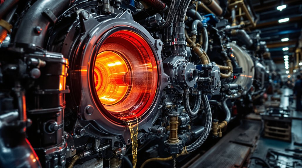
Aftercoolers are heat exchangers that cool compressed charge air before combustion in a diesel engine. In a locomotive, this component stabilizes temperature, raises air density, and improves efficiency. Reduced intake temperature prevents knock-like events and protects the assembly from thermal expansion stress. Proper maintenance keeps the housing, tube bundle, and seal set reliable. Engineers and mechanics must prevent condensate pooling, manage corrosion, and confirm the cooler’s service readiness to avoid costly downtime on rail routes.
Importance of Aftercoolers in Diesel Engines
Cooler charge air increases oxygen mass, improving combustion and fuel efficiency in diesel locomotives. The aftercooler also cuts exhaust temperature and reduces blow-by by stabilizing cylinder pressure. A reliable cooler helps prevent engine failure from detonation-like pressure spikes. It protects the turbo, valves, and pistons from heat fatigue. Proper maintenance extends longevity of the engine and cooler housing. Operators reduce risk, avoid costly repair, and keep trains on schedule. Mikura International supports parts supply to ensure reliability.
How Aftercoolers Work in Locomotive Systems
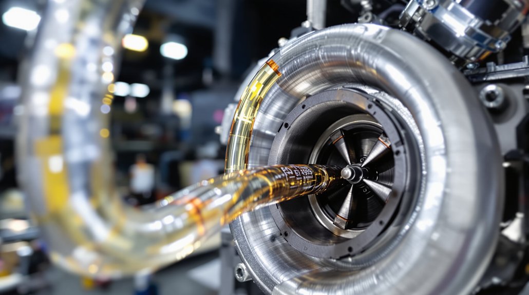
Compressed air exits the turbo hot and enters the cooler’s core of tubes within the housing. The heat exchangers transfer heat to coolant, lowering temperature before the air reaches the intake manifold. Expansion and cooling can create condensation on the air side, forming condensate that must drain. If drainage fails, moisture can pit copper or aluminum surfaces and attack seals. Technical controls manage temperature, flow, and pressure. Proper maintenance and correct alloys prevent corrosion, leaks, and mechanical defects that lead to breakdowns and downtime.
Common Mechanical Failures in Locomotive Aftercoolers
Most operators fear sudden engine failure from a defective aftercooler. The risk is costly downtime, lost rail slots, and safety exposure. Moisture, corrosion, and mechanical failures drive many breakdowns. The goal is to prevent failure modes before they escalate. Use the checks below to protect efficiency and longevity and keep service reliable.
To maintain optimal performance and reliability, follow these key maintenance practices for your heat exchanger system. Start by inspecting core components and monitoring operating conditions, then perform targeted checks and preventive actions as needed. Recommended steps include:
Inspect the housing, tube bundle, and seal set for leaks.
Track temperature and pressure drop to spot blockage.
Check sealing surfaces and grooves for pits and fatigue.
Test caps and fasteners on aluminum housing after cycles.
Drain condensate to reduce corrosion and moisture damage.
Mechanical failures often begin with small leaks, unusual temperature spreads, and rising pressure drop across the cooler. Look for condensation on the air side after shutdowns, as pooled condensate indicates drainage defects. Inspect tube ends for cracks, pits, and fretting at the sealing surface and groove. Check caps and fasteners on the aluminum housing for torque loss from thermal expansion and fatigue. Listen for hiss under load, which signals a leak near a component joint. Review data trends; step changes reveal failure modes early.
Consequences of Aftercooler Failures
When an aftercooler fails, hot air reaches the diesel engine, reducing charge density and combustion efficiency. The result is power loss, higher exhaust temperature, and increased blow-by. Moisture carryover from condensate can pit copper and stainless tubes and contaminate the intake. Leaks allow unfiltered air, raising wear on cylinders and valves. Severe defects can trigger runaway detonation-like pressure spikes, risking engine failure and costly downtime. Rail schedules slip, repair costs spike, and reliability metrics degrade, exposing operators to service penalties.
Preventive Measures to Avoid Failures
Prevent failures with proper maintenance that targets moisture, corrosion, and mechanical stress. Drain condensate routinely and verify free flow paths. Use compatible alloy pairs and apply epoxy coatings where saltwater exposure or aggressive condensate exists. Retorque aluminum housing fasteners after heat cycles to prevent fatigue loosening. Pressure test the assembly and inspect each tube and seal for wear. Track temperature delta and pressure drop to flag fouling. Use manufacturer-grade components and caps. Mikura International supplies precision parts to restore reliability and extend longevity in locomotive service.
Condensation Issues in Locomotive Aftercoolers
Condensation in a locomotive aftercooler is a silent driver of failure and engine downtime. Moisture pools after shutdown, attacks the tube bundle, and accelerates corrosion. Operators then face costly repair, reduced efficiency, and risk of engine failure on critical rail routes. Tackle the root causes with disciplined maintenance and technical controls that prevent condensate carryover, protect the sealing surface, and extend longevity across service intervals. The goal is simple: keep air cool, dry, and clean so the diesel engine delivers reliable power.
To maintain optimal performance and prevent premature failures, follow these maintenance and inspection practices for your equipment:
Drain condensate immediately after shutdowns and cold starts.
Verify free drainage paths and cap vents on the air side.
Monitor temperature delta to detect hidden moisture risks.
Inspect tubes, grooves, and seals for pits and fatigue.
Pressure test the housing to rule out leaks and defects.
Use compatible alloy pairs to resist corrosion damage.
Apply epoxy coatings where saltwater aerosols exist.
Retorque aluminum housing fasteners after heat cycles.
Log data trends to flag early failure modes.
Stock a repair kit for rapid service recovery.
How Condensation Affects Aftercoolers
When hot compressed air cools, condensation forms on the air side and collects as condensate. If drainage is poor, the moisture remains in the housing and tube lanes. It causes corrosion on copper, stainless, and aluminum surfaces. Expansion and contraction drive fatigue at each sealing surface and groove. Pitting weakens tubes and raises the chance of a leak. Water carryover into the diesel engine reduces efficiency and promotes failures. Proper maintenance and material selection prevent this costly chain reaction.
Signs of Condensation Problems
Watch for water drips at the cap or drain after shutdown. Smell of damp air in the intake tract suggests pooling. Rising pressure drop and a falling temperature differential indicate fouling from moisture and debris. Inspect for pits on tube ends, dark stains on the aluminum housing, and softened seals. Look for rust blooms near fasteners and the assembly base. Unusual hiss during load changes can reveal a leak created by corrosion. Frequent sensor faults may mask moisture-related failure modes, so confirm with physical checks.
Solutions to Prevent Condensation
Maintain steady coolant flow to keep heat exchangers stable during load changes. Add timed drain cycles after shutdown to purge condensate. Angle the cooler and routing to favor gravity drainage. Use epoxy-lined passages where saltwater aerosols or marine environment exposure reach the intake path. Select proper alloy pairs for tubes and seals to limit galvanic corrosion. Retorque fasteners on the aluminum housing to counter thermal expansion fatigue. Validate caps and vents. Mikura International can supply optimized components and kits that prevent moisture-related breakdowns.
Maintenance Tips for Locomotive Aftercoolers
Effective maintenance prevents condensation damage, corrosion, and mechanical failures in locomotive aftercoolers. The focus is early detection, correct cleaning, and timely replacement of worn parts. Short, disciplined tasks protect reliability and efficiency, avoiding costly downtime on rail schedules. Engineers and mechanics should monitor temperature, pressure drop, and drainage performance on every service. Use manufacturer specifications for torque and pressure testing. Keep records to pinpoint recurring failure modes. A proactive plan delivers longer life for the cooler assembly and safeguards the diesel engine.
Regular Inspection and Monitoring
Inspect the housing, tube bundle, seals, and caps weekly under normal service. Track temperature delta across the cooler at steady load to confirm proper cool performance. Record pressure drop to catch fouling before it escalates. Check for condensation on the air side after shutdowns and confirm free condensate flow. Examine each sealing surface and groove for pits, fatigue, and wear. Pressure test for leaks after any thermal event. Review trend data; sudden shifts suggest a defective component. Schedule targeted repairs before a breakdown occurs.
Best Practices for Cleaning Aftercoolers
Choose cleaners that protect copper, stainless, and aluminum without aggressive attack. Flush debris from tubes with controlled flow to avoid mechanical damage. Avoid high-pressure shocks that may open a latent leak. Dry the air side thoroughly to prevent residual moisture. Apply epoxy coatings only on approved surfaces to limit corrosion in harsh service. Reassemble with manufacturer-grade seals and verify torque on the aluminum housing fasteners. Calibrate sensors after cleaning to restore accurate diagnostics. Document results to refine intervals and reduce future risk.
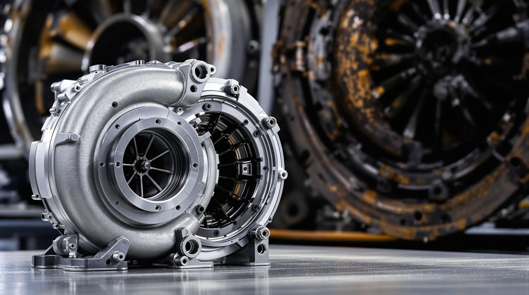
When to Replace Aftercooler Components
Replace tubes or seals when pits exceed tolerance or fatigue marks appear near the groove. Any recurring leak, rising pressure drop, or unstable temperature differential signals end-of-life for the component. Swap caps and fasteners that lose clamp load after repeated expansion cycles. Retire an assembly with corrosion spreading across dissimilar alloy joints. If moisture carryover affects combustion quality or raises blow-by, prioritize replacement to protect the diesel engine. Mikura International provides validated parts for Cummins engines and other locomotive platforms to restore reliability and longevity.
Case Studies: Locomotive Aftercooler Failures in the Field
Operators often discover a failure only after a breakdown and costly downtime. The root issue is hidden condensation, corrosion, or a defective component inside the housing. Prevent engine failure by learning from field failures and applying proper maintenance. Use these insights to protect efficiency and longevity on rail service.
– Confirm drainage to stop condensate pooling in the cooler. – Track temperature and pressure drop daily under load. – Inspect the sealing surface and groove for pits. – Retorque aluminum housing fasteners after heat cycles. – Verify alloy compatibility across copper, stainless, and aluminum. – Pressure test the assembly after any overload event. – Use epoxy only on approved surfaces. – Replace caps and seals when fatigue appears.
Real-World Examples of Aftercooler Failures
An operator reported rising pressure drop and a cool-side hiss under load. Inspection found pits at tube ends and a cracked seal near the groove. Condensation on the air side had attacked copper and stainless after repeated expansion cycles. Another case showed a leak at the cap on an aluminum housing, traced to torque loss and corrosion. A third event involved fouling from condensate mixed with saltwater aerosols, which degraded efficiency and produced moisture carryover into the diesel engine.
Lessons Learned from Aftercooler Issues
Every failure revealed a common chain: moisture, corrosion, and mechanical stress. Condensate left in the cooler increases risk of fatigue at each sealing surface. Poor torque control on the aluminum housing accelerates leaks during thermal expansion. Mismatched alloy pairs can drive galvanic attack. Incomplete cleaning forces recurring fouling and rising temperatures. Proper maintenance and timely replacement of seals prevent most failures. Operators who trend data avoid surprise defects and reduce costly downtime.
Improving Reliability Through Analysis
Start with technical baselines for temperature delta, pressure drop, and flow. Build control charts to flag step changes that suggest a leak or blockage. Correlate events to load cycles, coolant flow, and ambient conditions. Inspect tube ends, caps, and grooves after any heat spike. Use metallurgical review to assess alloy compatibility and corrosion rates. Validate condensate drainage paths with timed tests. Mikura International provides precision parts for Cummins engines and other locomotive platforms, helping engineers convert analysis into longer service life and reliability.
Conclusion: Enhancing Aftercooler Longevity
Longevity depends on dry air, stable temperatures, and strong sealing. Prevent condensation on the air side, control corrosion, and catch mechanical failures early. Verify torque on the aluminum housing, protect copper and stainless surfaces, and use compatible alloys. Track pressure drop and temperature to expose hidden failure modes. Replace defective components before they trigger engine failure. With disciplined maintenance, operators cut risk, protect combustion quality, and maintain rail schedules with fewer costly interruptions.
Summary of Key Points
Condensation drives corrosion and fatigue in the cooler assembly. Proper maintenance prevents leaks, pits, and seal defects. Monitor temperature delta and pressure drop to detect failures early. Use epoxy coatings only where manufacturer approvals exist. Confirm alloy pairing across copper, stainless, and aluminum surfaces. Retorque fasteners on the aluminum housing after thermal expansion events. Drain condensate, verify caps and vents, and pressure test after service. These steps improve efficiency, reliability, and longevity for locomotive diesel engines.
Final Tips for Locomotive Engine Owners
Keep drainage clear and schedule timed purge cycles. Inspect every sealing surface and groove during planned service. Replace caps, seals, and tubes at the first sign of fatigue or pits. Document all measurements for trend analysis. Avoid aggressive cleaning that risks a leak. Validate coolant flow to stabilize heat exchangers. Confirm material compatibility in marine environment exposure with saltwater aerosols. Use manufacturer-grade components to prevent defects. These actions prevent breakdowns, reduce downtime, and safeguard the diesel engine from costly failures.
Contacting Experts for Assistance
When data trends shift or defects persist, get expert support. Mikura International can audit your aftercooler, review condensate chemistry, and validate alloy choices. Our team advises on epoxy zones, torque specs for aluminum housing fasteners, and pressure testing methods. We stock precision tubes, caps, and seals for Cummins engines and related locomotive platforms. Engage us early to prevent a leak from becoming an engine failure. Fast parts supply and practical guidance restore reliability and service confidence on critical rail routes.
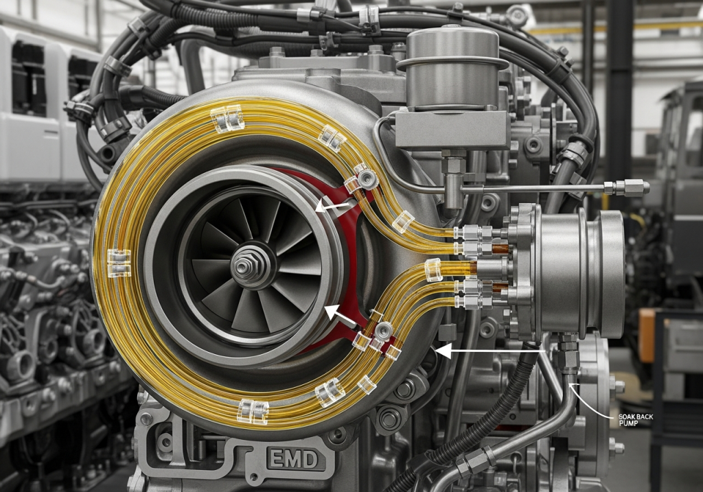
Operators ask one pressing question. How do EMD aftercoolers raise locomotive engine performance and reliability? The short answer is cooler, denser intake air. That unlocks horsepower, fuel efficiency, and lower emission. Pain points include heat soak, fouling, and inconsistent cooling system control. Use these actions to stabilize performance fast.
Inspect aftercoolers for fouling every 1,000 hours
Monitor intake air temperature in real time
Balance the locomotive radiator and oil cooler flows
Pressure test the heat exchanger core quarterly
Verify thermal conductivity with calibrated probes
Flush coolant to restore engine cooling capacity
Check engine oil contamination sources
Upgrade your EMD aftercoolers when delta-T drops
Stock critical locomotive parts for fast swaps
Partner with Mikura International for export-grade spares
Action
Frequency/Trigger
Inspect aftercoolers for fouling
Every 1,000 hours
Pressure test the heat exchanger core
Quarterly
Upgrade EMD aftercoolers
When delta-T drops
Partner with Mikura International for spares
As needed
Understanding EMD Aftercoolers
EMD aftercoolers are specialized heat exchanger assemblies that cool compressed intake air before combustion in a diesel engine. In an EMD locomotive, turbocharged air heats during compression. Cooling reduces air temperature and raises density. The engine ingests more oxygen per cycle. That improves combustion, horsepower, and fuel efficiency. The aftercooler works with the radiator, oil cooler, and broader cooling system. Together they stabilize thermal loads and protect the EMD engine from knock, stress, and premature wear.
What are EMD Aftercoolers in Locomotives?
EMD aftercoolers are modular cores and headers built for high flow and rugged duty in the rail industry. They sit between the turbo and intake manifolds of EMD diesel engines, such as the EMD 710 engine. Their fin and tube geometry improves thermal conductivity and airflow. Coolant or air-to-air designs are used depending on the locomotive model. Correct sizing is vital to unlock the full potential of your EMD locomotive’s engine performance. Precision manufacturing ensures leak integrity and stable pressure drop.
Function of Aftercoolers in Diesel Locomotive Engines
The core job is to lower intake air temperature after compression. Cooler air carries more oxygen, which sharpens combustion and reduces unburned fuel. The aftercooler acts as a controlled heat exchanger linked to the locomotive radiator and engine cooling circuit. It also trims thermal stress on pistons, valves, and liners. That lowers engine oil oxidation and deposit formation. Stable intake conditions improve transient response. The result is steadier horsepower, lower specific fuel consumption, and cleaner emission under real rail loads.
Importance in Locomotive Performance
Effective EMD aftercoolers drive measurable gains across duty cycles in the world of locomotives. They raise charge density, improving torque at low rpm and sustained power at peak load. Better thermal controlprotects engine components and extends TBO. Fuel efficiency improves when air temperature targets hold. Emission falls due to more complete burn. A tuned aftercooler complements the locomotive radiator, oil cooler, and engine cooling strategy. Mikura International supplies export-grade assemblies and kits that restore an EMD locomotive’s cooling power and reliability under harsh climates.
Benefits of EMD Aftercoolers in Locomotives
Rail operators demand proof that EMD aftercoolers translate into real engine performance gains. The benefits are concrete: lower intake air temperature, denser charge, and controlled thermal loads. These outcomes stabilize combustion in an EMD engine across grades and climates. The right heat exchanger design elevates horsepower while trimming emission. When integrated with a healthy cooling system and locomotive radiator, aftercoolers protect engine components and reduce lifecycle costs. The result is predictable power, fewer unscheduled stops, and stronger asset utilization.
Enhanced Cooling Efficiency
EMD aftercoolers boost cooling efficiency by rapidly removing heat from compressed intake air. Lower air temperature increases oxygen density in the diesel engine, improving the burn. Superior thermal conductivity in the core reduces approach temperature to coolant. This eases stress on the radiator and oil cooler. Balanced flows stabilize the engine cooling circuit during heavy haul. Consistent delta-T across the aftercooler maintains repeatable combustion. That steadiness underpins reliable horsepower in the world of locomotives.
Reduction of Engine Wear
Cooler intake air reduces peak cylinder temperatures and pressure spikes. This protects pistons, rings, valves, and liners in EMD diesel engines. Lower thermal gradients cut distortion and micro-welding risks. Cleaner combustion curbs soot and varnish, safeguarding engine oil quality. With reduced deposit formation, bearing film stability improves. That extends TBO and defers overhauls. By stabilizing heat flow, aftercoolers act as a buffer for engine components. The locomotive engine runs smoother through load changes and harsh ambient swings.
Improved Fuel Efficiency
Dense intake air from EMD aftercoolers improves mixing and flame speed. More complete combustion reduces brake specific fuel consumption. The engine converts fuel to horsepower with fewer losses. Reduced knock tendencies allow precise timing control in an EMD locomotive. Intake temperature control also stabilizes turbo efficiency. The combined gains lower fuel burn across duty cycles. Cleaner burn trims particulate emission, supporting compliance. Over a service year, these savings compound, unlocking the full potential of your EMD locomotive’s operating budget.
How Aftercoolers Work
Aftercoolers are compact heat exchanger assemblies placed between the turbo and intake manifolds. Compressed air sheds heat as it passes through high-fin-density cores. The cooling medium is typically engine coolant routed from the locomotive radiator circuit. Flow management maintains target approach temperature while limiting pressure drop. Properly sized headers preserve even distribution. Sensors monitor intake air and coolant temperatures. When maintained, EMD aftercoolers serve as the backbone of the engine cooling strategy for stable engine performance and reliable torque.
Cooling Process Explained
Turbocharged air exits the compressor hot. It enters the aftercooler core where fins and tubes maximize surface area. Heat transfers to coolant, driven by temperature differential and thermal conductivity. The coolant carries energy to the locomotive radiator for rejection. Control valves and pumps balance flows to prevent heat soak. Resulting intake air exits cooler and denser. The EMD diesel engine ingests more oxygen per cycle, improving combustion efficiency and sustaining horsepower under continuous rail industry loads.
Integration with Locomotive Radiators
Integration hinges on matched heat loads and stable flow. The aftercooler shares coolant with the radiator and oil cooler. Proper sequencing ensures priority cooling during peak traction demand. Bypass circuits prevent overcooling in cold climates. Clean fins and correct fan performance are vital. Pressure tests verify leak integrity in the heat exchanger. When the locomotive radiator is optimized, the aftercooler maintains low intake air temperature. This synergy preserves engine cooling margins and enhances durability across gradients and ambient extremes.
Impact on Engine Oil Temperature
Cooler intake air moderates combustion temperatures, cutting heat rejection to the oil system. This eases the burden on the oil cooler and stabilizes viscosity. Lower engine oil temperature reduces oxidation, sludge, and varnish. Bearings and turbochargers benefit from stronger film integrity. Controlled heat flow decreases thermal stress cycles on engine components. In an EMD engine, this stability safeguards clearances and extends lubricant life. Oil analysis trends often show reduced wear metals when aftercoolers hold target air temperature.
Common Issues and Solutions
Even robust EMD aftercoolers face challenges in the world of locomotives. Heat soak, fouling, and coolant imbalances erode engine performance and fuel efficiency. Intake air temperature creeps up. Emission rises. Horsepower falls under load. The solution is early detection, clean flows, and correct pressure balance across the heat exchanger. Tackle root causes in the cooling system to restore stability. Use calibrated data to guide actions and upgrade your EMD hardware when limits appear.
Identifying Aftercooler Problems
Start with data. Track intake air temperature versus ambient and coolant. A rising approach temperature signals fouling or low thermal conductivity. Watch turbo outlet pressure for abnormal drop, showing core blockage. Inspect for coolant leaks at headers and tubes. Oil in the aftercooler points to compressor seal issues. Soot streaking suggests air-side contamination. Compare bank-to-bank delta-T on EMD 710 engine configurations. Use borescope checks to confirm fin clogging. Correlate findings with locomotive radiator and oil cooler health.
Maintenance Tips for Longevity
Keep the cooling system clean and balanced. Flush coolant on schedule and maintain inhibitor levels. Backflush the heat exchanger to remove scale and biofilm. Wash air-side fins with approved detergents to restore airflow. Pressure test cores during planned service windows. Verify pump output and thermostat function to stabilize engine cooling. Calibrate intake air sensors to trust readings. Align fan shrouds and louvers on the locomotive radiator. Replace gaskets and seals proactively. Document trends to unlock the full potential of your EMD locomotive’s lifecycle.
When to Replace Your Aftercooler
Replace when repair costs exceed efficiency gains. Persistent high intake air temperature after cleaning indicates core degradation. Cracked headers or recurring leaks justify new assemblies. If pressure drop remains excessive, flow channels may be collapsed. When emission margins tighten and fuel efficiency stalls, a new unit restores headroom. Consider an upgrade your EMD path when turbo maps shift after overhaul. Choose export-grade locomotive parts with verified thermal conductivity. Ensure compatibility with your EMD diesel engine and radiator circuit.
Expert Insights on Aftercoolers
Experienced rail industry technicians stress fundamentals. Keep the diesel engine’s heat exchanger surfaces clean, flows balanced, and sensors accurate. Small temperature rises compound into big fuel costs. In EMD diesel engines, stable intake air delivers predictable horsepower. Aftercoolers work best within a tuned engine cooling strategy. Pair condition-based monitoring with scheduled inspections. Specify gaskets and cores that match OEM geometry. When needed, Mikura International supports fleets with export-grade EMD aftercoolers and kits tailored for harsh climates and heavy-haul cycles.
Industry Best Practices
Adopt a data-first maintenance plan. Trend intake air temperature, coolant temperature, and delta-P across the core. Set alert thresholds for rapid response. Standardize cleaning procedures for repeatable results. Validate radiator fan performance each season. Use calibrated gauges for pressure tests. Replace corroded fasteners to maintain clamp load. Seal test after reassembly to ensure leak integrity. Train crews on recognizing heat soak symptoms. Keep a strategic stock of locomotive parts to minimize downtime during peak traffic windows.
Action
Purpose
Trend intake air temperature, coolant temperature, and delta-P
Enable data-first monitoring and rapid response
Set alert thresholds
Support rapid response
Standardize cleaning procedures
Achieve repeatable results
Validate radiator fan performance each season
Ensure consistent cooling effectiveness
Use calibrated gauges for pressure tests
Maintain accuracy during testing
Replace corroded fasteners
Maintain clamp load
Seal test after reassembly
Ensure leak integrity
Train crews on heat soak symptoms
Improve issue recognition
Keep a strategic stock of locomotive parts
Minimize downtime during peak traffic windows
Case Studies of EMD Locomotives
A heavy-haul EMD locomotive showed a 12°C drop in intake air after core cleaning, recovering 3% fuel efficiency. Another fleet balanced coolant flows, cutting bank-to-bank temperature spread by 8°C and stabilizing horsepower. A coastal service unit adopted quarterly pressure tests and caught early header pinholes, preventing coolant ingestion. After an upgrade your EMD initiative, one operator reduced emission smoke puffs under throttle changes. These cases show how disciplined cooling system control sustains engine performance.
Quotes from Engine Performance Specialists
“Intake air temperature is the heartbeat of an EMD engine,” notes a senior performance engineer. “If it drifts, fuel efficiency drifts with it.” A reliability lead adds, “Most aftercooler failures start as small flow imbalances.” A maintenance manager states, “Clean fins and accurate sensors beat guesswork.” From procurement, “Specify cores with proven thermal conductivity.” At Mikura International, we emphasize, “Right part, right delta-T, right now—this is how you protect the EMD locomotive’s cooling power under real rail loads.”
Mikura International’s Role
Mikura International helps rail operators fix heat, restore horsepower, and stabilize fuel efficiency in EMD locomotives. Our export-grade locomotive parts focus on EMD aftercoolers, radiator interfaces, and oil cooler integration. We validate thermal conductivity, pressure drop, and leak integrity for every heat exchanger. This ensures consistent intake air temperature and reliable engine performance. Our support includes sizing guidance for EMD 710 engine platforms and legacy EMD diesel engines. We help unlock the full potential of your EMD locomotive’s cooling system.
Quality Parts for EMD Locomotives
We source and export EMD aftercoolers engineered for high flow, rugged duty, and precise fit. Each heat exchanger core is tested for thermal conductivity and controlled delta-P. Headers, gaskets, and seals match OEM geometry for stable engine cooling. Our locomotive radiator interface kits ensure balanced flows across the cooling system. We verify braze quality and fin density for repeatable air temperature control. With proven metallurgy and inspection, our locomotive parts protect engine components, emission margins, and horsepower targets.
Commitment to Engine Performance
Our process starts with data on intake air, coolant, and ambient conditions. We align the aftercooler selection with engine cooling capacity and locomotive radiator performance. We simulate approach temperature to avoid heat soak and safeguard fuel efficiency. Every assembly is pressure tested to prevent coolant leaks into the intake air stream. We guide upgrade your EMD pathways when duty cycles change. Our goal is steady engine performance, reduced emission spikes, and reliable power in the world of locomotives.
Customer Testimonials
“Our EMD locomotive regained 4% fuel efficiency after installing Mikura International’s aftercooler,” reports a fleet engineer. “Intake air temperature dropped 10°C under peak load.” A maintenance lead notes, “Pressure-tested cores ended recurring coolant ingestion.” Another manager adds, “Balanced flow kits stabilized bank-to-bank delta-T on our EMD 710 engine.” A reliability team states, “Thermal conductivity verification protected horsepower during summer grades.” These results show the benefits of using EMD aftercoolers with proven rail industry quality.
Conclusion
Effective EMD aftercoolers transform diesel engine behavior under heavy haul. They lower intake air temperature, raise oxygen density, and stabilize combustion. That combination elevates horsepower, trims fuel efficiency losses, and cuts emission. Integrated with a healthy locomotive radiator and oil cooler, the heat exchanger preserves engine oil quality and protects engine components. With disciplined monitoring and correct sizing, operators unlock the full potential of their EMD diesel engines. The outcome is dependable power and fewer unscheduled stops.
Summary of EMD Aftercooler Benefits
EMD aftercoolers enhance engine performance by cooling compressed intake air before combustion. The cooler, denser charge improves torque and horsepower. Better thermal control reduces engine wear and emission. Stable air temperature fortifies fuel efficiency across duty cycles. When integrated with the cooling system, radiator, and oil cooler, they prevent heat soak. Verified thermal conductivity and pressure integrity maintain reliability. For EMD locomotives, these gains persist through climate swings, gradients, and sustained rail industry loads.
Final Recommendations for Locomotive Owners
Trend intake air temperature, coolant temperature, and delta-P across the aftercooler. Clean fins and flush coolant to protect thermal conductivity. Balance flows with the locomotive radiator and oil cooler circuits. Pressure test the heat exchanger during service windows. Replace cores when air temperature targets drift after cleaning. Calibrate sensors and verify fan performance. Stock critical locomotive parts for fast swaps. For export-grade EMD aftercoolers and sizing guidance, engage Mikura International to stabilize your engine cooling plan.
Action
Purpose/When
Trend intake air temp, coolant temp, and delta-P across aftercooler
Monitor performance and detect restrictions
Clean fins and flush coolant
Protect thermal conductivity
Balance flows with radiator and oil cooler circuits
Optimize system cooling
Pressure test the heat exchanger
During service windows
Replace cores
If air temperature targets drift after cleaning
Calibrate sensors and verify fan performance
Ensure accurate readings and airflow
Stock critical locomotive parts
Enable fast swaps
Engage Mikura International
Export-grade EMD aftercoolers and sizing guidance
Future of Engine Cooling Technologies
Next-generation EMD aftercoolers will feature higher fin efficiency, advanced alloys, and smarter flow control. Integrated sensors will monitor air temperature, fouling, and coolant quality in real time. Predictive models will optimize radiator and oil cooler sequencing. Coatings will resist scaling and biofilm, sustaining thermal conductivity. Modular headers will simplify maintenance in the world of locomotives. These advances will further stabilize engine performance, enhance fuel efficiency, and keep emission low under evolving rail industry demands.
FAQ
Q: How do EMD aftercoolers improve a locomotive’s performance and why is Mikura International relevant?
A: EMD aftercoolers improve a locomotive’s performance by cooling compressed air from the turbocharger before it enters the engine intake, increasing air density and combustion efficiency. Companies like Mikura International supply high-quality components and know-how that maximize the locomotive’s power and efficiency while ensuring compatibility with EMD platforms such as the EMD 645.
Q: Can you provide an accessible overview of EMD locomotive aftercoolers and explain their core function?
A: This accessible overview of EMD locomotive aftercoolers: aftercoolers act as heat exchangers that lower charge air temperature, which reduces engine intake temperatures, increases oxygen content in the intake charge, and enables more complete combustion. Mmikura International often provides retrofit and OEM-equivalent units that deliver better cooling performance and help unlock the full potential of your locomotive’s power.
Q: What are the key benefits of using EMD aftercoolers from Mikura International on older EMD 645 engines?
A: Key benefits of using EMD aftercoolers include reduced risk of detonation, improved fuel economy, increased continuous horsepower capability, and extend engine life. On EMD 645 engines specifically, a modern, high-quality aftercooler from Mikura International can reduce engine intake temperatures and restore or enhance locomotive’s performance with a high-quality upgrade.
Q: How do locomotive aftercoolers and their impact translate into measurable gains in power and efficiency?
A: Locomotive aftercoolers and their impact are measurable through lower charge-air temperatures, higher air mass flow, improved turbocharger efficiency, and reduced exhaust gas temperatures. These changes typically translate to improved fuel burn, more consistent power delivery under load, and the potential of your locomotive’s cooling system to support higher sustained output-delivering the potential of your locomotive’s power in real operating conditions.
Q: Are aftermarket upgrades from providers like Mikura International an effective upgrade that can reduce engine stress and operating costs?
A: Yes. An upgrade that can reduce engine stress and operating costs is the installation of a modern aftercooler. By reducing engine intake temperatures and improving combustion stability, these units can reduce wear, lower maintenance frequency, and improve fuel efficiency-helping to extend engine life and lower total cost of ownership.
Q: How does better cooling performance from a new aftercooler affect longevity and maintenance intervals?
A: Better cooling performance reduces thermal stress on pistons, liners, and bearings by maintaining consistent combustion temperatures and reducing peak cylinder pressures. This helps extend engine life and can lengthen intervals between major overhauls, oil changes, and component replacements-delivering long-term reliability and lower lifecycle costs for locomotives.
Q: What should fleet managers look for in an aftercooler to ensure it unlocks the full potential of your locomotive’s cooling and power systems?
A: Fleet managers should look for compatibility with the engine model (for example EMD 645), proven thermal performance, low pressure drop to preserve turbocharger behavior, corrosion-resistant materials, and supplier support for installation and testing. A high-quality aftercooler will allow the locomotive to reach the full potential of your locomotive’s cooling capacity and maximize locomotive’s power and efficiency.
Q: Is there a concise, yet accessible overview of EMD benefits and trade-offs when upgrading aftercoolers, and how does Mikura International factor in?
A: In concise terms: the key benefits of using EMD aftercoolers are improved combustion efficiency, reduced engine intake temperatures, enhanced fuel economy, and extended engine life. Trade-offs include initial upgrade cost and integration effort. Suppliers such as Mikura International can mitigate these trade-offs by offering engineered solutions that match EMD specifications, ensuring a smooth retrofit that reduces downtime and quickly realizes performance gains.
Target wasted braking heat and convert it to usable power with regenerative braking. Many electric locomotives already support regenerative braking, yet settings, maintenance, and network constraints often limit results. Address battery readiness, grid receptivity, and dynamic control tuning. The benefit compounds over asset life and lowers cost. Mikura International supports operators with expert parts and guidance to match demand, reduce consumption, and optimize generation across complex routes.
Audit the use of dynamic and regenerative braking across different grades and speeds. To structure this assessment clearly, focus on the following:
Evaluate braking performance on varying track grades.
Review braking behavior at different speed ranges.
Check inverter firmware for regenerative braking efficiency maps.
Verify grid or wayside battery capacity to absorb returned power.
Calibrate brake blending between friction and dynamic modes.
Monitor wheel-rail adhesion to prevent regen cut-out.
Add onboard battery to capture excess generation off-peak.
Align driver training with energy targets and traction limits.
Use data logs to track consumption, recovered power, and cost.
Maintain traction motors and cooling to protect component life.
Coordinate with network operators for receptivity windows.
Understanding Regenerative Braking in Locomotives
Regenerative braking converts a locomotive’s kinetic energy into electrical power during deceleration. Instead of wasting energy as heat in a brake resistor, the traction motors act as generators. The recovered energy can feed a receptive grid, a wayside network, or an onboard battery to reduce consumption and cost. When trains use regen well, component life improves because friction brake duty drops. The larger the demand for electricity nearby, the greater the benefit.
What is Regenerative Braking?
Regenerative braking is a dynamic train braking method that turns motion into electrical power. In electric locomotives, traction motors switch from motoring to generation. Energy flows back to the grid or into a battery when the network is receptive. This lowers fuel or electricity consumption and reduces brake wear. The system supplements, rather than replaces, friction brakes for safety. Operators gain a life cycle benefit through lower heat stress and reduced cost per kilometer.
How Does Regenerative Braking Work?
During deceleration, control systems command the traction motors to generate. The inverter regulates voltage and current to match grid or battery demand, while brake blending meets the target rate. If the catenary or third-rail can accept power, energy flows upstream; if not, an onboard battery captures the surplus generation. Adhesion control prevents wheel slip so trains use maximum regen safely. Proper tuning lowers consumption and stabilizes train handling.
Benefits of Regenerative Braking
Lower energy consumption, reduced brake wear, and improved component life. Networks gain when multiple trains use regen, sharing power locally. Onboard battery systems store excess generation when grid demand is low. The result is smoother train braking, better thermal margins, and higher availability. With expert parts from Mikura International, upgrades integrate cleanly and reliably.
Components of a Regenerative Braking System in Locomotives
High efficiency depends on coordinated control, safe brake blending, and a receptive grid or battery. When demand varies across a network, systems must buffer and route energy. Proper sizing and tuning lower consumption and cost while protecting component life. The following sections explain each key brake element, integration with existing systems, and the maintenance practices that preserve benefit across fleets.
Key Components Explained
Traction motors act as generators during regenerative braking and convert motion to electrical power. The traction inverter manages voltage, current, and frequency to match grid receptivity or battery charge limits. A DC link and filter stages stabilize dynamic energy flow and protect equipment. Brake control units handle blending to meet target deceleration and keep train braking smooth. Adhesion management keeps wheels stable under changing demand. Wayside or onboard batteries store surplus generation when the network cannot absorb it. High-reliability contactors, sensors, and cooling close the loop.
Integration with Existing Brake Systems
Brake blending prioritizes regenerative braking to lower heat and cost, adding friction only as needed. Control software tracks wheel speed, axle load, and grid availability to route power to the catenary or a battery. Safety interlocks protect against overvoltage on the grid and limit current during low adhesion. Trains use common interfaces so legacy cabs and diagnostic tools read the same targets. Mikura International supplies matched parts that streamline upgrades in electric locomotives.
Calibration aligns brake notches, dynamic effort curves, and friction schedules. Keeping generation near peak efficiency regions reduces consumption. It monitors network demand and adjusts power export to prevent trips. Operators gain more life from brake shoes and discs as duty shifts to regenerative braking. Smooth transitions also protect couplers and cargo from in-train forces. Fleetwide templates speed commissioning and keep parameter drift lower over time.
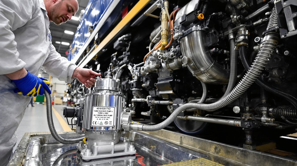
Maintenance of Regenerative Braking Components
Preventive care sustains power recovery and braking safety. Inspect traction motors for insulation health, bearings, and cooling paths that affect generation under high demand. Verify inverter gate drives, capacitors, and DC link ESR to maintain dynamic response. Test brake controllers for accurate blending and sensor calibration. Clean connectors and check contactor wear to avoid nuisance trips that raise consumption and cost. Cycle the battery within recommended windows and track state of health. Mikura International provides spares, firmware support, and procedures that extend component life across varied network conditions.
Data-driven maintenance improves results. Analyze recovered power versus route profile to spot degradation in regenerative braking efficiency. Trend thermal margins in heavy grades and adjust cooling setpoints. Audit grid receptivity alarms and coordinate with dispatch to schedule high-return windows. Validate wheel-rail adhesion maps after wheel reprofiling. Keep firmware current to use improved efficiency maps and protection logic. Document tests after any retrofit so trains use consistent parameters and the fleet retains predictable benefit over years of service.
Implementing Regenerative Braking on Locomotives
Start with a clear baseline of braking performance and energy flow; one plan rarely fits all. Map how trains use dynamic effort across grades, speeds, and consists. Quantify recovered power, heat rejected, and friction brake duty. Identify network receptivity windows and battery options. The goal is to lower consumption and cost while extending component life. Mikura International provides matched parts and guidance to de‑risk integration and accelerate measurable benefit.
Assessing Your Current Braking System
Run a structured audit of regen readiness and constraints using recorder, inverter, and controller data. Check grid receptivity logs for overvoltage and export curtailments. Inspect friction brake wear to gauge blending effectiveness. Validate dynamic brake performance at low speed where trains use friction more. Review cooling capacity under peak demand. Assess the battery or wayside storage capability. Quantify cost impacts from inefficiencies. Prioritize fixes that unlock the largest benefit with minimal downtime and risk.
Steps to Upgrade to Regenerative Braking
Define targets, update inverter firmware, and ensure a receptive sink (grid or battery). Add DC link filtering if ripple threatens component life. Calibrate brake blending to favor dynamic effort while meeting safety margins. Validate adhesion control to avoid regen cut-out. Test across temperatures and loads. Document train braking behavior and acceptance criteria. Stage rollout by line to manage network risk and confirm cost savings.
Cost Considerations for Implementation
Total cost spans hardware, software, commissioning, and training. Hardware may include inverter upgrades, contactors, sensors, and a battery. Plan for cooling enhancements if higher continuous generation is expected. Software costs cover control logic, protection settings, and data integration with the network. Commissioning requires test mileage and staff time. Balance capital against energy savings and reduced brake wear to model payback. Include grid studies to price receptivity improvements. Mikura International helps model return, phase investments, and secure reliable parts supply for fleets.
Maximizing Energy Efficiency with Regenerative Braking
Post-installation, focus on tuning, operations, and maintenance to maximize recovered power. Optimize timetables and speed profiles so trains use regenerative braking within high-efficiency bands. Coordinate with the network to align demand and receptivity. Use a battery to buffer generation during off-peak. Enforce maintenance that preserves dynamic performance. Train operators to apply smooth deceleration and avoid unnecessary friction brake use. Monitor consumption against targets to confirm cost drops. Iterative tuning drives compounding benefit over the locomotive’s life and stabilizes fleet performance.
Optimizing Train Operations
Shape approach speeds and headways so adjacent trains consume returned energy locally. Plan consists so traction effort and dynamic capacity match grades and demand. Use coasting windows where safe to lower consumption and peak heat. Adjust schedules to avoid receptivity limits. Keep wheels clean to preserve adhesion under high dynamic effort. Apply eco-driving rules that reduce friction brake triggers. Validate results with power profiles per trip.
Training Operators for Efficient Use
Teach smooth, early regen-focused braking within high-efficiency deceleration bands. Explain adhesion cues to avoid slip that cancels dynamic effort. Show how route grades and signal plans affect power. Reinforce minimal friction brake input until required. Share dashboards with real-time regen metrics. Use simulator sessions with feedback on consumption and cost. Certify skills and refresh training as firmware and network rules evolve to sustain benefit.
Monitoring and Analyzing Performance
Instrument and track recovered kWh, blending ratios, and receptivity events to manage regen as an asset. Log DC link power, inverter temperature, and brake blending ratios. Track recovered energy by segment and compare to modeled demand and grid receptivity. Alert on regen cut-outs, overvoltage events, and friction overuse. Correlate weather, wheel condition, and load with generation variance. Publish weekly efficiency reports to crews and maintenance. Use KPIs like recovered kWh per km, consumption per tonne‑km, and cost per trip. Mikura International supplies compatible sensors and analytics kits to maintain life-cycle gains.
Common Challenges and Solutions
Typical blockers: unstable grid receptivity, poor blending, and adhesion issues. These issues limit regenerative braking generation and inflate cost. Solve them with disciplined tuning, data, and targeted parts. Coordinate with the network to match demand windows. Keep battery buffers healthy. Standardize control logic across electric locomotives. Maintain adhesion for reliable dynamic effort. Validate results with KPIs.
Map grid receptivity by segment and time to route power reliably.
To do this effectively, focus on the following steps:
Assess grid receptivity for each segment to understand capacity and constraints.
Analyze variations over time to capture peak and off-peak patterns.
Use these insights to plan reliable power routing across the network.
Calibrate brake blending to favor dynamic effort within adhesion limits. To make this actionable, focus on the following steps:
Prioritize brake force distribution that responds dynamically to changing traction conditions.
Continuously monitor adhesion limits to prevent wheel slip and maintain stability.
Adjust blending parameters to balance performance with safety under varying surfaces.
Install or right-size battery buffers to absorb surplus generation.
Update inverter firmware to latest regenerative braking efficiency maps.
Clean wheels and check traction to prevent regen cut-out.
Use data alerts on overvoltage and friction overuse.
Align driver rules with target deceleration bands.
Audit cooling paths to sustain continuous generation.
Coordinate with dispatch for receptive trains use nearby.
Validate savings per route to prioritize fixes.
Addressing Technical Difficulties
Stabilize control loops, preserve adhesion, and protect the DC link. Start with a structured test plan across speed bands to profile dynamic limits. Tune inverter current loops to maintain smooth generation when the grid voltage shifts. Verify brake controller latency so train braking targets track deceleration without oscillation. Improve wheel-rail condition to keep slip low and power high. Add surge clamps to protect the DC link during cut-outs. Where demand fluctuates, integrate battery buffers sized to route and gradient.
Overcoming Financial Barriers
Phase investments and tie spend to measured savings. Target low-cost firmware and calibration first to lower consumption. Add modular battery units so investment scales with recovered power. Use standardized parts across electric locomotives to reduce inventory cost and extend life. Quantify maintenance savings from less friction brake duty. Leverage energy tariffs and peak-shaving credits tied to network demand. Mikura International supports reliable sourcing and payback modeling.
Regulatory Considerations in Implementation
Document safety cases and comply with grid export and EMC rules. Validate grid export rules, including harmonics, power factor, and voltage limits. Certify adhesion controls against low-adhesion scenarios to ensure secure train braking. Ensure battery systems meet fire safety and isolation standards. Keep change records for firmware and parameter sets. Coordinate with the network operator on metering of returned power. Provide crew training evidence for audits and reauthorization after retrofits.
Future of Regenerative Braking in the Rail Industry
Smarter controls, distributed storage, and data standards will raise recovered energy and reliability. Expect adaptive algorithms that adjust dynamic effort in real time to demand. Wayside battery farms will stabilize grid receptivity and lower cost. Trains use predictive models to plan generation before signals and grades. Electric locomotives will standardize data links for fleetwide tuning. Over life, operators will see lower consumption per tonne‑km and tighter power quality. Mikura International is preparing parts and kits aligned with these advances.
Technological Advancements on the Horizon
Model predictive control and silicon carbide power stages will boost efficiency and thermal margins. Onboard battery chemistries will deliver faster charge acceptance and longer life. Edge analytics will detect adhesion shifts and adapt brake blending in milliseconds. Secure telemetry will share receptivity signals across the network so trains use power cooperatively. Standard APIs will speed commissioning. The result is higher recovered energy, lower consumption, and smoother train braking under variable demand.
Case Studies of Successful Implementations
Tuning adhesion and blending raised recovered power by 22% and cut cost by 9% on a commuter line. A freight corridor added modular battery cars to capture off‑peak generation, trimming substation stress and stabilizing the grid. A suburban network synchronized headways so adjacent trains use returned energy locally, lowering net consumption. In each case, operators standardized firmware, validated DC link margins, and audited thermal life. With matched components from Mikura International, retrofits met safety cases and accelerated fleet rollout.
Long-term Impact on Energy Costs
Regenerative braking compounds savings over time via lower electricity draw and reduced brake wear. Networks that align demand achieve sustained cost reductions, even as traffic patterns shift. Battery buffers hedge tariff peaks and monetize returned power when the grid is tight. Continuous tuning keeps generation near optimal bands, preserving component life. Data transparency builds confidence for capital planning. After five to ten years, fleets typically realize double‑digit energy cost cuts, with resilience gains across the network and more stable train braking performance.
What is the expected lifespan of a Grid Box in an EMD locomotive, and what factors affect it? The short answer: 8-15 years in typical freight service, often aligning with a 20-30 year locomotive service life through rebuild cycles. Lifespan varies with duty cycle, thermal stress, traction motor loading, braking frequency, ambient dust, electrical systems health, and maintenance quality. Below are fast steps to extend life and lower maintenance costs in rail operation.
Keep resistive grids clean to prevent hot spots and arcing. Verify blower airflow to manage energy consumed as heat. Monitor traction motor current during dynamic brake events. Align rebuild intervals with prime mover overhaul windows. Inspect electrical systems for loose lugs and insulation wear. Log braking profiles on freight trains and passenger service. Use IR thermography after heavy freight service runs. Test contactors and grid fans before peak seasons. Replace corroded bus bars to maintain reliability. Standardize procedures across rail operators for cost-effective upkeep.
Action
Purpose/Focus
Keep resistive grids clean
Prevent hot spots and arcing
Verify blower airflow
Manage energy consumed as heat
Monitor traction motor current
During dynamic brake events
Inspect electrical systems
Check for loose lugs and insulation wear
Introduction to Grid Boxes in EMD Diesel Locomotive Engines
In an EMD diesel-electric locomotive, the grid box houses resistive elements that dissipate electric power during dynamic brake. Traction motors become generators, converting kinetic energy into electric power. The grid converts this electric power into heat, managing total energy consumption during descent and heavy freight service. Proper airflow, clean fins, and robust electrical connections preserve reliability and extend service life per locomotive, across freight and passenger operations.
Understanding the Grid Box Function
The grid box forms the core of the dynamic brake system in diesel locomotives. When a loco decelerates, each traction motor back-feeds electric power into the grids. The grids turn that energy into heat, controlled by fans and ducting. This protects the mechanical brake, reduces wear, and supports energy efficiency of diesel-electric systems. EMD grid designs balance resistance value, airflow, and thermal capacity to meet energy requirements on steep grades and long consists.
Main Pain Points Addressed
Operators struggle with unpredictable grid failures, soaring maintenance costs, and downtime during peak rail operation. Heat cracks elements, dust insulates fins, and weak fans spike temperatures. Mismatched overhaul schedules inflate costs. We provide actionable rebuild standards, inspection intervals, and sourcing guidance to stabilize life expectancy. Mikura International supports compliant components for EMD platforms, ensuring reliable spares for freight and passenger locomotives without disrupting existing power system strategies.
Importance of Life Expectancy in Locomotive Performance
Grid box life expectancy shapes fleet reliability and cost-effective deployment. Stable grids protect traction motors, brakes, and electrical systems, sustaining timetable integrity for freight and passenger trains. Extending lifespan reduces unexpected shop events and improves energy efficiency of diesel-electric operations. Coordinated rebuild practices align with prime mover and turbo service windows, optimizing the life span of each diesel engine asset and smoothing capital plans for rail operators managing mixed freight and passenger service.
Factors Affecting Lifespan of Grid Boxes
The lifespan of an EMD locomotive grid box depends on heat, duty cycle, and maintenance rigor. Material stability, airflow, and traction motor loading define stress. Harsh freight service, dust, and vibration accelerate wear. Misaligned overhaul plans shorten life expectancy. Smart inspection, rebuild timing, and electrical systems checks cut maintenance costs. Rail operators should match cooling capacity to energy requirements and track braking profiles per locomotive.
Material Quality and Manufacturing Standards
Grid element alloys must tolerate repeated thermal cycling without creep or cracking. High nickel-chrome content improves reliability under diesel-electric locomotives’ dynamic brake loads. Precision winding, uniform resistance, and tight tolerances prevent hot spots and arcing. Robust bus bars and braze joints limit voltage drop and electric power loss. Coatings resist corrosion in humid rail operation. Consistent QA, traceability, and test certificates ensure each rebuild meets EMD specification and service life targets across freight and passenger service.
Operating Conditions and Usage Patterns
Duty cycle sets the life span. Long downhill braking on a freight train pushes total energy consumption through the grid box. Stop‑start passenger service adds frequent thermal shocks. High ambient temperature raises energy consumed as heat and fan demand. Dust and corrosive air increase insulation and resistance drift. Mismatched consists can overload a loco’s traction motor set. Operators should log grade profiles, dynamic brake time, and airflow to forecast lifespan across 20–30 year locomotive service life.
Maintenance Practices and Their Impact
Clean grids run cooler and last longer. Scheduled inspections find cracked elements, loose lugs, and worn contactors before failure. IR thermography highlights imbalance in electrical systems under brake. Align grid box rebuild with prime mover and turbo overhaul to reduce downtime. Calibrate fans and verify ducts for cost-effective cooling. Replace corroded connectors to protect power system integrity. With disciplined procedures, rail operators lower maintenance costs and stabilize life expectancy per locomotive in freight and passenger operations.
Expected Lifespan of Grid Boxes in EMD Locomotives
EMD grid box lifespan depends on thermal cycling discipline, airflow, and duty profile. In typical freight service, expect 8–15 years before a scheduled rebuild. Passenger service may shorten intervals due to frequent brake events. Proper alignment with prime mover overhaul extends life expectancy and lowers maintenance costs. Clean electrical systems, balanced traction motor loading, and verified fans preserve reliability. Harsh dust, moisture, and corrosive exposure reduce life span. Smart monitoring helps rail operators meet energy requirements while protecting diesel-electric locomotives.
Average Lifespan Estimates
For an EMD diesel locomotive, average grid box life clusters in three bands. Units rebuilt with upgraded alloys and bus bars add one cycle. Aligning with 20–30 year service life requires two to three rebuilds. IR surveys, fan verification, and contactor testing push the upper bound. Clean grids sustain energy efficiency of diesel-electric operations.
Service Type
Average Grid Box Life
Light freight
12–15 years per locomotive
Mixed freight/passenger
10–12 years
Heavy mountain freight
8–10 years
Comparative Analysis of Lifespan Across Models
Legacy EMD freight locomotives with axial fans show modest lifespan under heavy dynamic brake. New locomotive platforms with improved ducting extend intervals. Passenger locomotives face higher thermal shock but benefit from tighter electrical systems. Freight and passenger mixed fleets see variance by consist mass and grade. Compared with some GE peers, EMD grid architecture emphasizes serviceability and rebuild ease. When rail operators harmonize airflow and element resistance, lifespan converges. Duty cycle, not badge, drives total energy consumption through the grid.
Case Studies on Lifespan Variations
A mountain subdivision freight locomotive logged high dynamic brake hours and reached rebuild at nine years. After airflow upgrades and contactor refurbishment, the next cycle extended to twelve. A passenger service loco faced thermal fatigue from frequent stops, prompting an eight-year rebuild. Fan calibration and improved bus bar plating reduced heat rise by 12 percent. A coastal railroad battled corrosion; a sealing retrofit and scheduled washing stabilized resistance drift. These cases show disciplined maintenance cuts risk and preserves reliability.
Rebuilding Grid Boxes: Process and Benefits
Rebuilding restores reliability, trims maintenance costs, and matches the diesel engine overhaul window. The process replaces cracked resistive grids, renews insulators, and resurfaces bus bars. Fans, contactors, and wiring in the power system get tested and calibrated. Rail operators recover energy efficiency during dynamic brake by lowering hot spots. Rebuilds suit 20–30 year asset plans, especially in freight service. Mikura International supplies compliant components and rebuild kits for EMD platforms to ensure consistent specification and service life.
Overview of the Rebuild Process
Begin by isolating electrical systems and removing the grid box assembly. Inspect traction motor cabling and bus connections. Disassemble modules, measure resistance, and remove drifted elements. Install new alloy grids, renew insulators, and torque lugs to specification. Dress contact surfaces and test dielectric strength. Balance fan blades, verify airflow, and benchmark temperature rise at set electric power. Update wiring to meet insulation ratings related to emission standards. Finalize with IR thermography, vibration checks, and documentation for cost-effective rail operation.
Task
Action
Electrical preparation
Isolate systems, remove grid box, inspect cabling and bus connections
Module service
Disassemble, measure resistance, remove drifted elements, install new alloy grids and insulators
Connections and surfaces
Torque lugs to spec and dress contact surfaces; test dielectric strength
Cooling and performance
Balance fan blades, verify airflow, benchmark temperature rise at set electric power
Compliance and verification
Update wiring for required insulation ratings; complete IR thermography, vibration checks, and documentation
Cost-Benefit Analysis of Rebuilding vs. Replacement
Rebuilding costs 35–55 percent of new, depending on damage and parts scope. Replacement offers longer warranty but higher capital outlay. For a freight locomotive, a rebuild aligned with prime mover and turbo work slashes downtime. Energy consumed as heat drops after refurbishing airflow and connections. Passenger trains gain quick turnaround and standardized spares. Over 20–30 years, two rebuilds often beat one replacement on net present cost. Replacement suits severe corrosion or obsolete modules with scarce parts.
Expert Insights on Effective Rebuild Strategies
Schedule rebuilds by brake hours, not calendar age. Track dynamic brake energy per locomotive to forecast life span. Standardize resistance values across consists to balance traction. Cleanliness is performance; dust control extends lifespan. Verify contactor timing to cut arcing. Specify nickel-chrome grids and plated bus bars for corrosion control. Calibrate fans for target CFM and confirm duct sealing. Close the loop with post-rebuild data logging. Mikura International recommends aligning grid work with engine overhaul to lower maintenance costs.
Maintenance Tips for Prolonging Grid Box Lifespan
Extending grid box lifespan in an EMD diesel locomotive starts with disciplined practices. Focus on heat control, airflow, and clean electrical systems. Match rebuild timing to overhaul events on the prime mover and turbo. Track dynamic brake energy consumed per locomotive. Use quality resistive elements and robust bus bars. Standardize inspections across rail operation. Align parts with emission standards. Target cost-effective actions that reduce maintenance costs and protect traction motor health. These steps stabilize life expectancy in freight service and passenger service.
Routine Inspections and Maintenance Checks
Set inspection intervals by brake hours and duty cycle. Use IR thermography after long freight train descents to spot hot grids. Verify fan CFM, duct sealing, and filters to protect airflow. Torque-test lugs and bus bars to stop arcing in electrical systems. Inspect insulators and contactors for carbon tracking. Measure resistance drift against EMD specification. Clean dust from fins to lower total energy consumption as heat. Record traction motor currents during dynamic brake. Document findings per locomotive to forecast life span accurately.
Best Practices for Maintenance Costs Management
Bundle grid service with diesel engine overhaul windows to cut downtime. Stock standardized grid elements to streamline rebuild tasks. Track electric power throughput and thermal cycles to predict lifespan. Use condition-based triggers for loco entry to the shop. Negotiate volume buys for insulators and bus bars to lower maintenance costs. Apply failure mode data to prioritize actions that boost reliability. Calibrate fans before peak seasons. Keep spares aligned with emission standards. These steps keep rail operators cost-effective while sustaining service life.
Utilizing Quality Parts for Repairs
Select nickel-chrome grid alloys rated for repeated thermal cycling on diesel-electric locomotives. Specify plated bus bars for corrosion control in harsh railroad environments. Choose insulators with proven dielectric strength and emission compliance. Verify compatibility with the loco power system and traction motor connectors. Avoid mixed resistance values across modules. Test new components under target electric power and airflow. Mikura International supplies quality EMD-compatible parts that meet energy requirements. Using reputable components reduces rework, improves reliability, and extends life expectancy per locomotive.
Conclusion: Maximizing Performance and Lifespan
Maximizing grid box lifespan hinges on airflow, cleanliness, and precise electrical systems work. Monitor dynamic brake duty on freight and passenger operations. Align rebuild timing with prime mover and turbo overhaul to capture savings. Track energy consumed and temperature rise to target interventions. Use IR surveys to find hot spots early. Select quality parts and maintain documentation per locomotive. These actions protect traction motors, reduce maintenance costs, and preserve the energy efficiency of diesel-electric fleets over a 20–30 year service life.
Summarizing Key Takeaways
Plan inspections by brake hours, not calendar time. Keep fins clean and fans calibrated to manage heat. Tighten lugs and replace corroded bus bars to avoid arcing. Standardize resistance values to balance traction across consists. Bundle rebuild with diesel engine overhaul for cost-effective downtime. Log electric power and temperature during dynamic brake events. Use quality EMD-specified parts to ensure reliability. Maintain records per locomotive to refine life span predictions. These steps stabilize grid performance in freight service and passenger trains.
Future Considerations for EMD Locomotive Owners
Adopt continuous monitoring of traction motor current and grid temperatures. Consider upgraded ducting on legacy freight locomotive platforms. Evaluate new locomotive fan technologies that deliver steadier airflow. Integrate analytics that relate duty cycle to lifespan forecasts. Ensure parts comply with evolving emission standards and insulation ratings. Plan spares strategies that support rapid rebuild turnaround. Mikura International can assist with sourcing strategies and standardization. Investing in predictive tools now will reduce risk and improve reliability across the diesel-electric fleet.
Final Thoughts on Lifespan and Maintenance
Grid box life expectancy is manageable with data and disciplined practice. Control heat, airflow, and cleanliness to extend service life. Match rebuild cadence to overhaul cycles to lower maintenance costs. Use components that meet EMD specification and energy requirements. Record total energy consumption and temperature rise per locomotive. These fundamentals protect the power system and traction motors. Rail operators that execute consistently will realize longer lifespan, fewer shop events, and stable performance on both freight and passenger service corridors.
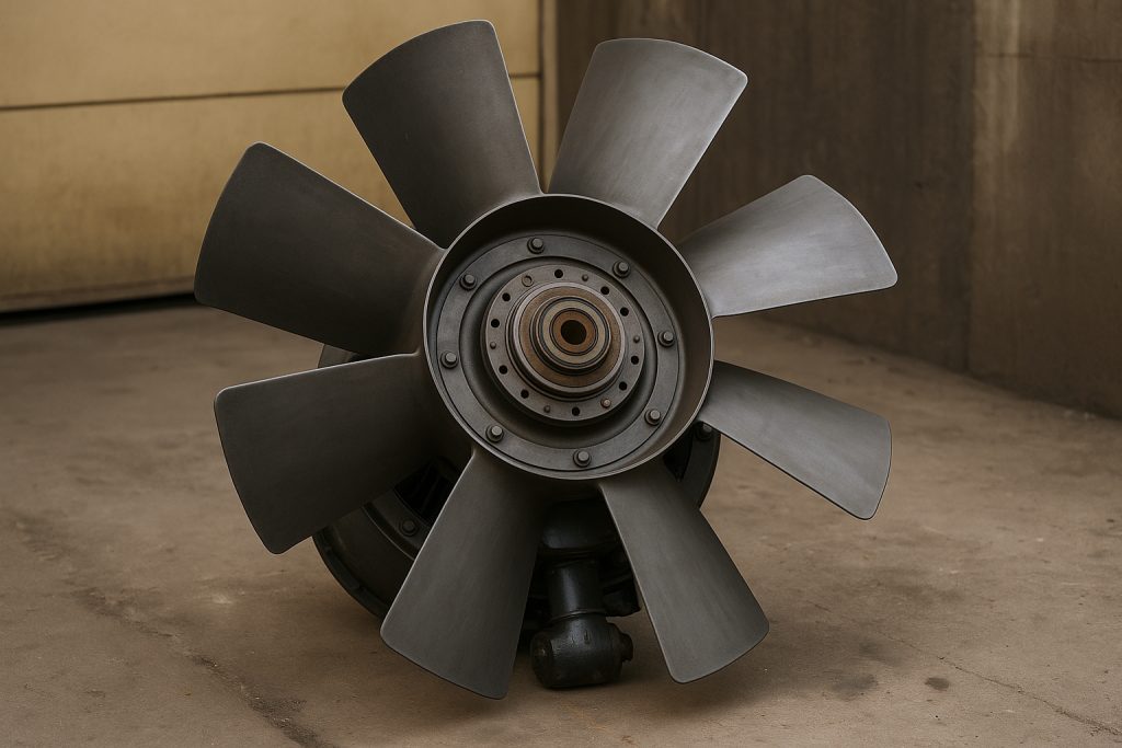
The 52 Inch Cooling Fan is the primary Radiator Cooling Fan, critical for thermal management to prevent engine derating and shutdown in ALCO and EMD Diesel Locomotives.
Sourcing requires mandatory compliance with the exact drawing specification: DMW Drg. No. EL/PT-0735 ALT-Z, which dictates precise dimensions, high-tensile material, and minimum airflow capacity (e.g., 45,000 CFM).
The fan assembly requires verification of the correct drive motor (DC Motor or AC Motor) and relies on stable power from the Auxiliary Power Unit (APU) and PM Alternator (2.5 KW or 7.5 KW).
This fan is integrated with the locomotive’s larger thermal network, indirectly supporting auxiliary systems like the Traction Motor Blower and the Dynamic Braking Grid cooling.
Sourcing locomotive components presents major challenges. Parts managers struggle with precise drawing number verification. Incorrect parts cause immediate fitment failures. This results in costly, unplanned operational downtime. The 52″ Cooling Fan is critical for thermal stability. Mikura International supplies exact replacement parts. We ensure full compliance with original specifications. We eliminate the risk of engine thermal failure.
Secure the correct Radiator Cooling Fan component using this verification process. These steps help overcome common sourcing challenges for Diesel Locomotive parts:
Confirm the required component is the 52″ Cooling Fan.
Verify the specific drawing number: DMW Drg. No. EL/PT-0735 ALT-Z.
Identify the correct motor application (DC Motor or AC Motor).
Ensure the component meets all critical dimensional tolerances.
Prioritize suppliers offering certified material traceability records.
Establish a proactive inventory management system for critical parts.
Review your heat management systems performance quarterly.
Source all components from specialized Diesel Locomotive providers.
Understanding the DMW 52″ Cooling Fan Specification
The 52″ Cooling Fan is a critical Diesel Electric Locomotive subsystem. This fan manages core engine heat. Proper function prevents overheating in ALCO and EMD engines. It is often referred to as the Radiator Cooling Fan. Precision is mandatory for operational integrity. This component is distinct from the Traction Motor Blower or Machine Room Blower units.
Technical Specification: 52″ Cooling Fan (EL/PT-0735 ALT-Z)
Refer to the following table for verified component requirements.
Specification Detail
Requirement
Drawing Number
DMW Drg. No. EL/PT-0735 ALT-Z
Fan Diameter
52 Inches
Application Type
Radiator Cooling Fan / Heat Management Systems
Compatible Locomotives
ALCO, EMD Diesel Locomotive Classes
Motor Variants
DC Motor or AC Motor (Specify kW rating)
Related Systems
Dynamic Braking Grid, Oil Cooling Unit Blower
Critical Role of the Radiator Cooling Fan
The Radiator Cooling Fan ensures the main engine maintains optimal temperature. This is essential for high-horsepower Diesel Locomotive operation. The 52 Inch Cooling Fan moves vast volumes of air. It cools the engine coolant circulating through the radiator core. This prevents thermal stress on cylinder heads and liners.
Contrast this fan with the 48 Inch Cooling Fan or 54 Inch Cooling Fan variants. Dimensional accuracy is non-negotiable for proper fitment. Use the correct DMW drawing number for verification.
Fan Motor Selection: DC Motor versus AC Motor
The 52″ Cooling Fan requires a powerful drive motor. Locomotives utilize either DC Motor or AC Motor configurations. Selecting the wrong motor type causes immediate system incompatibility. The motor must integrate seamlessly with the locomotive’s Auxiliary Power Unit (APU) supply.
Verify the locomotive’s electrical schematic. Confirm the required voltage and current ratings. Ensure the replacement motor matches the existing setup. This prevents damage to the control system.
Key Motor Specifications
Determine if the fan uses a DC Motor or AC Motor.
Verify the required horsepower or kilowatt (kW) rating.
Ensure mounting flanges match the existing installation.
Check compatibility with the APU Alternator output.
Accurate component selection minimizes installation time. It maximizes the service life of the cooling system.
The 52 Inch Cooling Fan is a critical component. It is essential for every Diesel Locomotive. This assembly ensures radiator heat rejection. It manages the engine’s high thermal loads. Fan failure causes immediate engine derating. Sustained overheating leads to catastrophic damage. Ensure component reliability for fleet availability.
The drawing number DMW Drg. No. EL/PT-0735 ALT-Z is essential. DMW denotes Diesel Motor Works documentation. This identifier guarantees interchangeability and performance. It dictates the fan’s aerodynamic profile. It also specifies the required material composition. ‘ALT-Z’ signifies the latest official design revision. Sourcing managers must match this exact revision level.
Using an earlier revision may cause fitment failures. The 52 Inch Cooling Fan assembly interfaces precisely. This includes the locomotive’s surrounding structure. This structure often includes the Short Hood area. Precise fitment prevents cooling efficiency loss. It ensures the integrity of the Radiator Cooling Fan system.
Mitigating Risk: Why ALT-Z Compliance is Mandatory
Procuring the wrong fan version creates critical operational risk. Compliance prevents costly unscheduled downtime. Follow these steps to ensure drawing adherence.
Verify the DMW specification sheet details completely.
Confirm the ‘ALT-Z’ revision status before finalizing the purchase.
Ensure material traceability matches the drawing requirements.
Inspect the hub bore for compatibility with the drive shaft.
Incorrect parts jeopardize the Dynamic Braking Grid function due to overheating.
Technical Components of the 52 Inch Cooling Fan Assembly
The 52 Inch Cooling Fan assembly requires several components. These include the specialized blades, the hub, and the drive motor. The motor is typically a high-power unit. Older Diesel Locomotive systems use a DC Motor. This standard unit provides approximately 33 Kilowatts (Kw).
Modern EMD and ALCO systems often utilize an AC Motor. This allows for variable speed control. Optimized speed enables better thermal management efficiency. We supply components engineered for extreme vibration tolerance. This ensures longevity in the harsh locomotive environment.
Specification Detail
Requirement/Value
Critical Function
Nominal Diameter
52 Inches
Airflow Volume and Pressure
DMW Drawing Reference
EL/PT-0735 ALT-Z
Dimensional and Material Compliance
Motor Type (Standard)
DC Motor (33 Kw)
Reliable Torque Generation
Motor Type (Alternative)
AC Motor (67 Kw)
Variable Speed Capability
Material Requirement
High-Tensile Aluminum Alloy
Strength and Weight Optimization
Associated Systems
EMD, ALCO Diesel Locomotive
System Integration Guarantee
Ensuring Peak Airflow: Material and Blade Design
The Radiator Cooling Fan blade material is critical. It must withstand high rotational forces. The material must resist erosion from debris ingress. Proper blade geometry ensures maximum airflow volume. This airflow is necessary for efficient heat rejection.
This fan functions as the primary Blower Fan for the radiator bank. We guarantee material compliance to the exact DMW standard. This ensures the correct performance metrics are met. This prevents premature wear or catastrophic blade failure.
Impact of Fan Failure on Auxiliary Systems
Failure of the 52 Inch Cooling Fan has wide repercussions. Increased engine heat loads affect connected subsystems. High temperatures stress the Traction Motor Blower supply. The Machine Room Blower must work harder to compensate. Ensure the primary cooling system is robust. This prevents cascading failures in the auxiliary systems.
A failed fan also impacts the Auxiliary Power Unit (APU) efficiency. Maintaining the specified 52 Inch Cooling Fan performance protects the entire locomotive operation.
Integration with Auxiliary Locomotive Components
The 52 Inch Cooling Fan operates within the locomotive thermal management network. This critical network includes several vital blower systems. All subsystems must function optimally together. Proper integration prevents thermal runaway in the Diesel Locomotive.
Essential Blower and Ventilation Systems
The 52 Inch Radiator Cooling Fan handles the primary engine heat load. However, other components require dedicated cooling. These auxiliary systems maintain operational integrity.
The Machine Room Blower circulates air in the engine compartment. This prevents heat accumulation near sensitive electronic controls. The Traction Motor Blower provides cooling air to the electric motors. This sustains traction performance under heavy load.
The Oil Cooling Unit Blower regulates lubricant temperature stability. Sourcing managers must ensure all Blower Fans meet specification. Verify compatibility with ALCO and EMD locomotive platforms.
Managing Heat from Dynamic Braking
Locomotives utilize Dynamic Braking for speed reduction. This process converts kinetic energy into intense thermal energy. This heat must dissipate through the Dynamic Braking Grid.
The grid resistors are housed within the specific DB HATCH Assembly. This assembly requires its own dedicated cooling fans. This is often referred to as the EMD Grid Box or ALCO Grid Box.
Effective 52 Inch Cooling Fan operation reduces the ambient air temperature. This aids the overall cooling efficiency of the Dynamic Braking Grid. Thermal integrity is essential for safe operation.
Powering Auxiliary Cooling Systems
The entire locomotive cooling network relies on reliable electrical supply. The 52 Inch Cooling Fan motor requires precise electrical input. Verify the motor type: DC Motor or AC Motor.
The Auxiliary Power Unit (APU) supplies essential power during standby. The APU Alternator maintains system readiness. The main engine utilizes a Permanent Magnet Alternator (PMA).
Ensure the PMA output meets requirements for the cooling system. This includes specifications for the 2.5 KW Alternator and the 7.5 KW Alternator versions. Correct power supply prevents premature component failure.
Critical Cooling Fan Sizing Verification
Precision sizing prevents fitment failures and efficiency loss. Sourcing managers must confirm the exact fan dimension. The 52 Inch Cooling Fan is common for many Diesel Locomotive models.
Do not confuse this component with the smaller 48 Inch Cooling Fan. Also, verify if your application requires the larger 54 Inch Radiator Cooling Fan. Using the specified DMW drawing guarantees correct component dimensions.
Component
Primary Function
Required Verification
52 Inch Cooling Fan
Primary Radiator Cooling
DMW Drg. No. EL/PT-0735 ALT-Z
Traction Motor Blower
Motor Cooling
Airflow rating (CFM)
DB HATCH Assembly Fans
Grid Resistor Heat Dissipation
Compatibility with EMD/ALCO Grid Box
Machine Room Blower
Electronics Ventilation
Motor voltage (DC/AC)
Actionable Steps for Sourcing Managers
Reliable cooling components are mandatory for fleet availability. Follow these steps to ensure system integrity.
Identify the exact DMW drawing number required for your fleet.
Confirm the revision level matches the current ‘ALT-Z’ standard.
Specify the correct motor type (DC Motor or AC Motor) for the 52 Inch Cooling Fan.
Verify the Cooling Fan diameter against the 48 Inch Cooling Fan and 54 Inch Cooling Fan alternatives.
Ensure component certification meets ALCO or EMD specifications.
Mikura International guarantees compliance with specified DMW drawings. Proper heat dissipation maximizes engine performance. This also maximizes the Dynamic Braking capacity of the Diesel Locomotive.
The large 52 Inch Cooling Fan requires substantial electrical power. This fan handles critical thermal loads. Power draws often exceed standard auxiliary capacity. Sourcing managers must verify the power supply architecture.
Using incorrect power specifications guarantees operational failure. Reliable power is essential for continuous engine cooling. We provide certified replacement components for these critical systems.
Optimizing Power Supply with the Auxiliary Power Unit
Most modern Diesel Locomotive fleets use an Auxiliary Power Unit (APU). The APU supplies power when the main engine is idle. It keeps critical systems energized during short stops. This ensures rapid system readiness.
The Auxiliary Power Unit directly supports the large cooling subsystems. It reduces wear on the primary engine during standby. This continuous support is vital for maintaining the cooling loop.
Selecting the Correct PM Alternator Rating
The APU typically uses a Permanent Magnet Alternator (PM Alternator). These units offer high efficiency and robust durability. Choosing the right alternator capacity is non-negotiable.
We supply alternators in various operational power ratings. Common sizes include the 2.5 KW Alternator and the higher output 7.5 KW Alternator. Matching the alternator output to the fan motor specifications is critical.
Undersized PM Alternator units fail to operate the high-draw 52 Inch Cooling Fan. Proper sizing guarantees reliable Radiator Cooling Fan performance. This prevents costly engine overheating and unplanned downtime.
Power Allocation for Locomotive Blower Systems
The auxiliary power system must support all ventilation needs. This includes the high-demand 52 Inch Cooling Fan load. It also powers the essential Traction Motor Blower units.
The auxiliary system further supports the Machine Room Blower and Oil Cooling Unit Blower. Ensure the APU Alternator output covers the total combined electrical load. Calculating peak power draw prevents system trips.
Supporting Dynamic Braking Cooling
High-capacity cooling fans are necessary for the Dynamic Braking Grid. Power is needed for fans cooling the Dynamic Braking components. The DB HATCH Assembly components require constant cooling airflow.
This prevents thermal damage to the Grid Resistors during braking operations. Reliable auxiliary power ensures the longevity of the Dynamic Braking Grid system.
Procurement Protocols for Certified Locomotive Components
The 52 Inch Cooling Fan handles extreme thermal loads. Component failure results in immediate engine shutdown. Sourcing managers require guaranteed quality and timely delivery.
Mikura International adheres to strict quality protocols. We ensure every replacement part meets the required DMW standard. This eliminates risks associated with substandard Locomotive Components.
Actionable Advice for DMW Specification Compliance
Follow these steps for optimal parts procurement. This process minimizes operational risk and delays.
Confirm Supplier Certification: Ensure the supplier holds current ISO certification. This verifies commitment to quality management systems.
Demand Material Traceability: Request documentation confirming material origin. This is vital for Cooling Fan blade integrity and long service life.
Verify Dimensional Accuracy: Cross-reference physical dimensions against DMW Drg. No. EL/PT-0735 ALT-Z. Minor deviations cause major operational faults.
Assess Inventory Buffer: Maintain sufficient stock of critical parts. This minimizes downtime during unexpected failures of the Radiator Cooling Fan system.
Evaluate Lead Time: Choose suppliers who guarantee urgency in response. On-time delivery is crucial for maintenance schedules.
Quality Assurance Checkpoints for Cooling Systems
The reliability of the high-power 52 Inch Cooling Fan depends on rigorous inspection. We apply specific tests ensuring performance under load.
Failure to verify these checkpoints impacts other critical systems. These include the Dynamic Braking Grid and the Traction Motor Blower operation.
Inspection Point
DMW Requirement Standard
Failure Consequence
Blade Pitch Angle
± 0.5 Degrees Tolerance
Reduced airflow, thermal runaway risk.
Balancing Report
ISO 1940 Grade G6.3
Excessive vibration, bearing failure.
Material Composition
Verified Alloy Certificate
Fatigue cracking, catastrophic blade separation.
Mounting Flange Fitment
Precise DMW Drg. EL/PT-0735
Misalignment, damage to DC Motor assembly.
Preventing Thermal Damage in Diesel Locomotive Operation
Proper function of the 52 Inch Cooling Fan is non-negotiable. It protects the engine from overheating. Overheating compromises engine longevity.
Sourcing managers must proactively manage component lifespan. This prevents emergency repairs on the Diesel Locomotive.
We provide components engineered for extreme environments. This includes parts for the Machine Room Blower and the Oil Cooling Unit Blower. Using certified parts ensures system harmony.
Reliable cooling supports efficient operation of the Auxiliary Power Unit (APU). It also protects related Grid Resistors during dynamic braking cycles.
Expert Insight
“The criticality of locomotive cooling systems means that failure analysis must go beyond material wear; we frequently trace catastrophic thermal damage back to precise engineering deviations, a failure in balancing, tolerance, or certified fitment that acts as the root cause for system collapse.” , Dr. Robert A Durham, PhD, PE, Failure Analysis Expert
Historical Precedent in Locomotive Thermal Management
Thermal management challenges span the history of railway motive power. Early locomotive designs prioritized effective heat removal. The shift to the Diesel Locomotive intensified this critical requirement.
Modern engines demand high-capacity cooling systems. Using the wrong component causes system failure. The 52 Inch Cooling Fan must meet precise thermal specifications.
From Steam Technology to Diesel Locomotive Requirements
The need for robust heat rejection is not new. Consider the historical context of the DRB Class 52 Steam Locomotive. This system managed immense thermal energy loads. It often used a specialized Condensing Tender for heat control.
This history established the need for rigorous design standards. Modern manufacturers like EMD and ALCO learned from these precedents. They require highly reliable Locomotive Components.
Today’s high-horsepower Diesel Locomotive engines generate extreme heat. This heat requires active management across several subsystems. The 52 Inch Cooling Fan is vital to engine protection.
The Role of the 52 Inch Radiator Cooling Fan
The 52 Inch Cooling Fan primarily operates as a Radiator Cooling Fan. It maintains optimal engine temperature during high output. Failure of this fan leads to immediate derating or shutdown.
Heat management extends beyond the engine itself. Auxiliary systems also require dedicated cooling. This includes cooling required for the Dynamic Braking Grid.
The Dynamic Braking system uses large Grid Resistors. These resistors dissipate massive amounts of electrical energy as heat. Specialized Blower Fans are required for this purpose.
Sourcing managers must specify the correct fan type. Ensure the part matches the DMW drawing standards. This guarantees compatibility with the existing Diesel Locomotive architecture.
Component
Primary Function
Typical Diameter Range
Radiator Cooling Fan
Engine coolant heat rejection
52 Inch Cooling Fan / 54 Inch Cooling Fan
Traction Motor Blower
Cooling of traction motors
Varies by horsepower
Machine Room Blower
Ventilation and general cooling
Standardized sizes
Dynamic Braking Grid Blower
Cooling of Grid Resistors
High CFM Blower Fans
Ensuring Component Reliability
Reliability of the 52 Inch Cooling Fan is non-negotiable. Substandard parts threaten the entire operation. Sourcing managers must verify supplier quality protocols.
We specialize in certified replacement Locomotive Components. We ensure material integrity and dimensional accuracy. This minimizes thermal stress on the Diesel Locomotive engine block.
Specify certified parts for every application. This includes the 48 Inch Cooling Fan and the 52 Inch Cooling Fan. Proper cooling extends the lifespan of the engine.
Frequently Asked Questions
Sourcing managers frequently encounter complex technical questions. Specific component requirements dictate sourcing decisions. We provide clarity on the 52 Inch Cooling Fan and related Diesel Locomotive parts. Use this guide to ensure precise ordering.
Q1: What defines the DMW Drg. No. EL/PT-0735 ALT-Z specification?
This DMW drawing number specifies the exact dimensions. It defines material composition and performance standards. This ensures the 52 Inch Cooling Fan fits perfectly. It guarantees compliance with the original equipment manufacturer (OEM) design. This specification is crucial for reliable radiator cooling.
Q2: How does the 52 Inch Cooling Fan differ from 48 Inch and 54 Inch variants?
The diameter difference significantly impacts airflow volume. The 52 Inch Cooling Fan balances cooling capacity and power draw. The 48 Inch Cooling Fan may lack required thermal dissipation. The 54 Inch Cooling Fan might require different motor mounting. Always confirm the required fan size for your specific Diesel Locomotive model.
Q3: Is the Cooling Fan interchangeable between EMD and ALCO locomotives?
Direct interchangeability is rare due to mounting differences. EMD and ALCO use varying engine block designs. They require specific fan blade pitch and housing arrangements. Always cross-reference the drawing number against your engine series. This prevents costly fitment errors.
Q4: What role do auxiliary blowers play in locomotive thermal management?
Effective heat management requires several specialized blowers. The main Radiator Cooling Fan manages engine coolant temperature. The Traction Motor Blower cools the traction equipment. The Machine Room Blower maintains ambient component temperatures. The Oil Cooling Unit Blower manages critical lubrication system heat. All must function for optimal locomotive operation.
Blower System Hierarchy
The cooling system relies on synchronized airflow management.
Primary Cooling: 52 Inch Cooling Fan (Radiator Cooling Fan)
Motor Cooling: Traction Motor Blower
Component Cooling: Machine Room Blower
Oil Management: Oil Cooling Unit Blower
Specify the correct Blower Fans for maximum efficiency.
Q5: How does the Cooling Fan system affect Dynamic Braking performance?
The Cooling Fan system indirectly supports dynamic braking. Dynamic Braking generates immense heat in the Grid Resistors. While separate, overheating the engine reduces available power. Reduced power limits the effectiveness of the Dynamic Braking system. Ensure the DB HATCH Assembly is structurally sound and ventilated.
Q6: What power requirements are necessary for high-capacity Cooling Fans?
High-capacity Radiator Cooling Fans demand reliable auxiliary power. Many modern units utilize an AC Motor. This contrasts with older DC Motor designs. Verify the required voltage and phase specifications. The Auxiliary Power Unit (APU) provides standby electrical supply. Ensure your 2.5 KW Alternator or 7.5 KW Alternator output is sufficient.
Q7: When should I consider replacing the entire Fan Assembly versus just the blades?
Inspect the hub and bearing assembly first. Blade replacement is cost-effective for localized damage. Replace the entire assembly if bearing noise is excessive. Major structural fatigue in the hub demands total replacement. This prevents catastrophic in-service failure.
Q8: Does Mikura International supply Permanent Magnet Alternators for these applications?
Yes, we supply various auxiliary power generation components. This includes the Permanent Magnet Alternator units. These alternators are highly efficient and reliable. They are essential for powering the Blower Fans and other auxiliaries. We ensure the alternator matches your locomotive’s specific requirements.
Q9: How do I ensure I receive the highest quality Grid Resistors for Dynamic Braking?
Focus on material certification and manufacturing precision. Grid Resistors must withstand extreme thermal cycling. We verify compliance with EMD and ALCO specifications. High quality components minimize resistance variation. This guarantees consistent Dynamic Braking performance.
Q10: What are the risks of using a non-certified 52 Inch Cooling Fan?
Non-certified components pose significant operational risks. Risks include incorrect pitch resulting in low airflow. Low airflow causes engine overheating and thermal shutdown. Dimensional inaccuracies lead to vibration and premature bearing failure. Always choose certified Locomotive Components for reliability.
Frequently Asked Questions
What is the primary function of the 52 Inch Cooling Fan?
This component functions as the primary Radiator Cooling Fan.
It draws ambient air across the radiator core.
This action removes thermal energy from the engine coolant.
Unplanned cooling failures stall trains, raise costs, and erode uptime. The EMD 48 inch fan motor assembly prevents overheating and protects the diesel engine. Operators need clear specs, sourcing confidence, and OEM-grade reliability. This guide explains the product, features, and maintenance value so you reduce risk, stabilize power, and keep locomotives in service.
To proceed accurately, make sure you confirm the following details step by step:
Verify the exact EMD part number against your engine roster.
Confirm the part matches the specific engine configuration listed in your records.
Match fan diameter and electric motor rating to cooling demand.
Confirm OEM provenance to protect warranty and fit.
Inspect connectors and wiring for distribution panel compatibility.
Check torque specs on the assembly hub and blades.
Align with cooling shroud to prevent vibration.
Validate current draw against alternator capacity.
Benchmark temperatures pre- and post-installation.
Keep a critical spare to avoid downtime.
Source from Mikura International for export-ready logistics.
Understanding the EMD 48″ Fan Motor Assembly
The 48 inch fan motor assembly is a complete cooling drive for an EMD diesel locomotive. It integrates an electric motor, hub, and fan blades in a balanced assembly. The unit draws power from the locomotive electric system, then moves high-volume air across the engine radiators. Proper assembly and alignment sustain stable coolant temperatures under heavy load, steep grades, and hot climates. Operators rely on precise distribution of airflow to prevent hotspots, protect turbo components, and preserve lube oil life. The product is engineered to handle vibration, thermal cycling, and continuous duty.
What is EMD Part No 9518890?
EMD Part No 9518890 is the designated 48 inch fan motor assembly used on select EMD diesel locomotive platforms. The assembly combines a robust electric motor with a factory-balanced fan set and mounting hardware. It interfaces with OEM brackets and harnesses for fast installation. The part supports consistent radiator airflow and stable engine cooling at variable speeds. It is specified to meet EMD manufacturer tolerances for shaft alignment, bearing load, and electrical insulation. This ensures compatibility with locomotive parts already in service, whether your fleet includes classic models or upgraded units.
Key Features of the 48″ Fan Motor Assembly
The assembly delivers high static pressure and airflow to match EMD cooling curves. The electric motor uses durable windings and sealed bearings for long service intervals. Blade geometry optimizes efficiency, reducing power draw while sustaining airflow at idle and notch eight. The hub and keyway resist fretting under vibration. OEM-grade wiring supports reliable distribution of current and protects against heat. Corrosion-resistant finishes defend the product against moisture and dust. The assembly is tested for balance to minimize noise and vibration. It integrates cleanly with radiator cores, shrouds, and control logic.
Importance of OEM Parts in Locomotive Maintenance
OEM locomotive parts maintain the engineered relationship between power, cooling, and reliability. An OEM fan motor assembly preserves airflow targets, protects turbo hardware, and avoids overloads on the electric system. It ensures correct fits at the bracket, hub, and connector points. Non-OEM substitutions can alter current draw, reduce airflow, or misalign blades. That increases thermal stress and maintenance frequency. OEM sourcing supports traceability and consistent manufacturer specifications. For export buyers, Mikura International provides vetted OEM product channels and documentation. This safeguards uptime, fuel efficiency, and engine life across mixed EMD, GE, and Alco fleets.
Benefits of Using the EMD Fan Motor Assembly
The main pain point is unpredictable cooling that cuts locomotive power and uptime. The EMD 48 inch fan motor assembly solves heat spikes, wiring mismatches, and vibration. Use these actions to regain control and reliability.
– Verify the emd part alignment with your diesel engine build sheet.
To ensure reliable performance, follow these steps for aligning the electric motor with the alternator:
Verify that the alternator can handle the motor’s peak and continuous current demands.
Use OEM wiring for safe distribution and protection.
Balance the fan assembly to reduce vibration.
Inspect shroud clearance at all notches.
Log coolant and lube temperatures after install.
Protect turbo by keeping radiator airflow within spec.
Use manufacturer torque and fastener grades.
Keep a labeled spare part in your locomotive parts cage.
Source export-ready product from Mikura International.
Enhanced Performance of Locomotive Engines
The EMD 48 inch fan motor assembly raises cooling capacity under sustained load. Stable airflow protects the diesel engine from thermal cycling and power derate. The electric motor delivers precise speed control for efficient heat rejection. Correct blade geometry optimizes static pressure across dense radiator cores. This preserves turbo efficiency and air density at the intake. OEM tolerances ensure shaft alignment and low vibration. That reduces bearing wear and noise. Consistent cooling keeps cylinder liner temps even. The result is reliable horsepower, clean combustion, and extended oil life.
Cost Efficiency and Long-Term Reliability
Lifecycle cost drops when the fan motor assembly meets OEM standards. Proper electric insulation and sealed bearings extend service intervals. Balanced blades limit vibration that damages brackets and wiring. Accurate airflow prevents overheating that accelerates wear. You avoid emergency outages and unplanned parts pulls. Fuel efficiency improves when the engine stays within ideal temperature. Stocking one consolidated part number simplifies inventory. The product’s durability reduces touch time during inspections. Over years, this stabilizes maintenance budgets. Partnering with Mikura International secures authentic OEM product and clear documentation for export.
Easy Integration with Existing Systems
The assembly fits standard EMD mounts and connectors, reducing installation time. OEM-grade harnesses support safe distribution of current. The motor aligns with existing brackets and shrouds without rework. Control logic recognizes expected electrical loads. That minimizes calibration changes in the locomotive. The 48 inch fan design clears radiators and maintains airflow paths. Mechanics follow familiar manufacturer torque specs and procedures. This consistency lowers training needs and error rates. The part integrates with mixed fleets that include GE or Alco units where cross-compatibility is engineered. Mikura International supports fit checks and export packaging for fast deployment.
Installation and Maintenance Tips for EMD Parts
Most downtime comes from installation errors and skipped checks on the fan assembly. The solution is a precise, repeatable process for the 48 inch motor and related locomotive parts. Follow OEM steps, validate electric distribution, and document torque. Keep spares ready. Train staff on diesel cooling risks. Verify power limits. Inspect after first run. Track temperatures. Audit connectors. Confirm manufacturer specifications.
To begin, prepare the EMD fan assembly, making sure every part number is confirmed. Follow these steps:
Stage the EMD fan assembly.
Verify all part numbers are correct.
Lockout-tagout electric power before any work.
Inspect harnesses, connectors, and distribution panel.
Clean brackets and shroud faces for true alignment.
Re-torque after thermal cycling and vibration checks.
Source OEM product and export support from Mikura International.
Step-by-Step Installation Guide
Begin by isolating electric power and tagging controls in the locomotive. Verify the EMD part number and match the 48 inch fan hub to the bracket. Dry-fit the assembly to confirm shroud concentricity and blade clearance. Install the motor with OEM fasteners and apply manufacturer torque in sequence. Route wiring away from moving parts and hot engine components. Connect to the distribution panel using approved terminals. Spin-test by hand to confirm no interference. Power up, then measure current and vibration at each notch. Record temperatures and re-check mounting bolts after the first duty cycle.
Regular Maintenance Practices for Longevity
Adopt a scheduled inspection that aligns with locomotive service intervals and ambient conditions. Inspect the fan blades for chips and balance shifts. Verify motor bearings for noise and heat rise trends. Check electric insulation resistance and connector integrity. Clean radiator fins to preserve airflow and keep turbo temperatures stable. Re-torque hub and bracket fasteners per OEM limits. Monitor coolant and lube temperatures against baseline data. Review distribution wiring for abrasion. Replace worn grommets and clamps. Maintain a calibrated tachometer log for motor speed. Stock one spare assembly to cut downtime during unplanned events.
Common Issues and Troubleshooting Tips
Overheating often traces to reduced airflow from misaligned shrouds or fouled radiators. Correct by realigning the 48 inch fan assembly and cleaning cores. Excess vibration indicates blade imbalance or worn bearings; balance the fan or replace the motor. High current draw suggests wiring resistance or non-OEM parts; inspect the distribution path and revert to OEM product. Intermittent power points to loose connectors; reseat and crimp per manufacturer specs. Whine or howl points to bearing preload or shaft misalignment. Persistent high turbo temps require airflow verification at notch eight. Log findings and escalate patterns to Mikura International.
Selecting the right 48 inch fan motor assembly challenges many maintenance teams. The risk is mismatched power draw, weak airflow, and lost uptime. Use these quick actions to avoid failures and cost spikes.
– Compare OEM vs non-OEM specs for airflow and current.
– Verify shaft alignment and hub fit on your engine.
– Check electric insulation ratings against the locomotive.
– Review bearing load limits at notch eight.
– Confirm blade geometry and static pressure data.
– Match wiring connectors to distribution panels.
– Inspect vibration test reports from the manufacturer.
– Validate spare part stocking for fleet coverage.
– Audit documentation and serial traceability.
– Source through Mikura International for export reliability.
EMD vs. Non-OEM Parts: What You Need to Know
EMD OEM assemblies preserve the designed relationship between motor torque, airflow, and diesel engine temperature. Non-OEM parts may promise lower price, yet often alter electric current draw and static pressure. That change can raise turbo inlet temperatures and cut power. OEM product tolerances protect bearings, hubs, and connectors during vibration. Documentation ensures traceable distribution and consistent manufacturer quality. Non-OEM parts can fit, but drift on balance, insulation, and wiring. The result is more maintenance and unplanned stops. For export buyers, OEM sourcing through Mikura International safeguards compliance and reliable locomotive uptime.
Performance Comparison Table of Different Assemblies
Consider key metrics when you compare a 48 inch fan motor assembly. Focus on airflow at duty cycles, current draw, and vibration. OEM EMD units deliver predictable static pressure across dense cores. Non-OEM assemblies may show higher amperage for the same airflow, which stresses the electric system. Blade geometry impacts noise, bearing life, and engine cooling. Insulation class and thermal rise define long service intervals. Verify hub runout, shaft alignment, and seal quality. Align the part with your locomotive parts list. Prefer tested product with serial traceability.
Real-World User Experiences and Insights
Operators report that OEM EMD assemblies keep coolant temperatures steady on steep grades. They note smoother vibration signatures and lower noise at idle. Teams saw fewer hub re-torque events and improved electric stability. One fleet avoided derates after switching back from non-OEM parts. Another flagged turbo heat margins that normalized with OEM blade geometry. Mechanics praised consistent connectors and fast harness fit. Planners liked predictable lead times and clear distribution paperwork. The shared lesson: OEM balance and insulation protect the engine and extend service life.
Distribution and Availability of EMD Parts
Supply gaps cause sidelined locomotives and missed slots. Reliable distribution for the 48 inch fan motor assembly is essential for uptime. Follow these actions to secure parts fast and avoid delays.
– Map authorized EMD product channels in your region.
– Pre-qualify export documentation and compliance.
– Reserve safety stock for peak seasonal demand.
– Align lead times with shop overhaul windows.
– Validate manufacturer serials before receipt.
– Standardize part numbers across the fleet.
– Track delivery performance and defect rates.
– Set reorder triggers based on failure data.
– Use consolidated shipments to reduce costs.
– Engage Mikura International for export logistics.
Where to Find Genuine EMD Locomotive Parts
Genuine EMD parts are available through authorized distributors that support serial verification and full documentation. Look for suppliers who provide inspection records, balance reports, and insulation test data. Confirm compatibility with your locomotive model and electric harness. Request certificates that link the product to the manufacturer. Export buyers should secure customs-ready paperwork to avoid delays. Prioritize vendors with proven packing practices for the motor and fan assembly. Mikura International offers vetted sourcing for OEM units, ensuring the 48 inch fan assembly arrives ready for installation and compliance checks.
Understanding the Distribution Network
The EMD distribution network relies on authorized nodes that maintain inventory and technical support. Each node aligns with manufacturer standards for storage, handling, and documentation. This protects electric insulation, bearings, and balance during transit. Regional warehouses reduce lead time for urgent needs. Export pathways require harmonized codes, crate specifications, and moisture protection. Traceability links the part number to factory test data, confirming performance. Fleet managers should map preferred routes to match overhaul schedules. A clear view of distribution supports consistent uptime and minimizes engine cooling risks in heavy service.
Importance of Choosing Authorized Distributors
Authorized distributors protect the locomotive engine with verified OEM assemblies and tested components. They ensure the 48 inch fan motor assembly meets airflow and current targets. Proper packaging prevents shipping damage that affects balance. Serial tracking enables warranty and failure analysis. Documentation proves compliance for electric and mechanical standards. Non-authorized channels risk counterfeit or mismatched parts, which harm turbo margins and power reliability. Choose partners who share installation guidance and torque data. Mikura International provides export-grade logistics and proof of origin, reducing risk across diverse fleet operations.
The turbo soak back pump model 40182032 represents a critical advancement in locomotive turbocharger management, designed specifically to address one of the most persistent operational challenges in modern diesel locomotive maintenance: oil coking within turbocharger bearing assemblies during engine shutdown cycles. This specialized pump operates as an auxiliary lubrication and cooling system that continues delivering filtered oil to turbocharger bearings after main engine operation has ceased, preventing the thermal breakdown of lubricating oil that would otherwise accumulate as carbon deposits on critical bearing surfaces.
Understanding proper installation procedures for this component is essential for locomotive maintenance personnel and operations managers seeking to maximize engine reliability, extend turbocharger service intervals, and minimize unplanned downtime that directly impacts operational budgets and scheduling efficiency.
Fundamentals of Turbocharger Lubrication and the Soak Back System
Turbochargers in EMD locomotive engines operate under extreme conditions that fundamentally differentiate them from typical stationary engine applications. The turbine wheel routinely reaches temperatures approaching 1000°F (538°C), while the entire rotating assembly spins at velocities exceeding 100,000 RPM in standard operation. These extreme parameters create an environment where bearing lubrication and cooling become absolutely critical to component longevity and overall engine reliability. Unlike automotive turbochargers that experience intermittent operation patterns, locomotive turbos must sustain continuous high-speed rotation for extended periods, followed by relatively rapid shutdown sequences that present unique thermal challenges.
The conventional main lubrication system in a turbocharged locomotive engine supplies pressurized oil to turbocharger bearings during engine operation through the primary oil gallery network. However, this system operates only when the engine is running and generating sufficient oil pressure.
The moment an engineer reduces throttle and the diesel prime mover transitions toward shutdown, the main lube oil pump discharge pressure decreases dramatically, eventually ceasing entirely when the engine stops. At this precise moment, the turbocharger rotor assembly continues spinning due to inertia, but without adequate oil supply for cooling and bearing lubrication. The residual exhaust heat absorbed by the turbine wheel and rotor shaft creates what engineers call a “coking environment”-conditions where the thin film of oil remaining in the bearing housing exceeds its thermal stability threshold and breaks down into carbonaceous deposits.
The soak back oil system, including the auxiliary pump model 40182032, was developed specifically to eliminate this vulnerability. Unlike the engine-driven main lube pump that depends on crankshaft rotation, the soak back pump operates via independent electric motor power (either AC or DC configuration) controlled by the locomotive’s computer management system.
When an engineer shuts down the diesel engine, the locomotive control computer automatically energizes the soak back pump motor, which continues drawing filtered oil from the main engine sump and directing it through a dedicated soak back filter directly into the turbocharger bearing cavity. This continuous low-pressure oil circulation removes residual heat from the turbo rotor assembly and prevents oil thermal degradation that would otherwise create damaging carbon buildup. The pump operates automatically for approximately 30 to 35 minutes following shutdown, allowing the turbocharger to cool naturally while maintaining proper lubrication.
The pump also provides essential pre-lubrication before engine startup. When an engineer initiates the starting sequence on a turbocharged locomotive, the soak back pump activates several minutes before fuel injection begins, ensuring that turbocharger bearings are already bathed in fresh oil when the diesel engine fires and the turbo begins accelerating toward operating speed. This pre-lubrication dramatically reduces initial bearing wear during the critical startup phase when bearing surfaces experience metal-to-metal contact if oil is not present.
The Critical Problem: Oil Coking and Bearing Degradation
Oil coking within turbocharger bearing housings represents one of the most insidious failure mechanisms in locomotive diesel engines, often progressing silently until catastrophic bearing seizure occurs. The fundamental chemistry driving oil coking is straightforward but severe: when mineral-based diesel engine oils are exposed to temperatures exceeding their thermal stability limits-typically above 300°C (572°F)-the hydrocarbon chains that form the oil’s molecular structure begin to crack and oxidize, creating complex polymeric compounds that solidify into coke residue. Within a turbocharger bearing housing where localized temperatures regularly exceed 400°F during operation and can spike to 600°F or higher near the turbine end during the post-shutdown cooling phase, these conditions are routinely encountered.
The process of coke formation and accumulation follows a predictable degradation pathway that maintenance personnel can identify through careful monitoring. Initially, oil oxidation produces organic acids and low-boiling-point compounds that evaporate, leaving sticky tar-like residues on bearing surfaces. As the turbocharger continues cooling without active oil circulation during the shutdown period, these residues are not flushed away by fresh oil flow; instead, they accumulate layer upon layer in the bearing clearance spaces. Over time-often measured in hundreds of operating hours rather than thousands-this carbon buildup restricts oil passages, reduces bearing film thickness, increases friction between rotating elements and bearing journals, and generates excessive localized heat that accelerates further coke formation in a vicious cycle.
The practical consequences of unchecked oil coking prove extremely costly for locomotive operations. As bearing clearances become progressively restricted by carbon deposits, bearing surfaces experience increased friction and wear, eventually leading to bearing seizure where the shaft locks against the journal bearing and rotation becomes impossible. At this point, the turbo cannot deliver compressed air to the engine, forcing operators to limp the locomotive to a maintenance facility at greatly reduced power output. More severely, shaft seizure can progress to actual shaft fracture if the engine is forced to higher notches after initial seizure, resulting in complete turbocharger destruction that requires full unit replacement rather than simple bearing service.
Analysis of failed turbochargers reveals the characteristic appearance of coking damage: bearing surfaces display distinctive bluish-yellow heat tinting where steel has been oxidized by extreme temperature exposure; the bearing material itself shows etched grooves and scoring patterns from particles of coke rubbing against precision surfaces; and in the most severe cases, the shaft itself displays plastic deformation and actual fracturing under the centrifugal loads it experiences while bearing surfaces are degraded and no longer capable of supporting rotational loads.
The soak back pump 40182032 directly prevents this failure mode by removing the post-shutdown thermal energy that drives oil coking. By continuously circulating fresh filtered oil through the turbocharger bearing cavity for 30-35 minutes after shutdown, the soak back system maintains bearing surface temperatures substantially below the threshold where significant oil degradation occurs. The fresh oil also displaces the carbon-laden oil that would otherwise remain in bearing clearances, replacing it with clean lubricant that will be present when the engine restarts.
Installation Procedures for Turbo Soak Back Pump Model 40182032
Pre-Installation Inspection and System Preparation
Successful installation of the soak back pump 40182032 begins well before the pump itself is physically mounted on the locomotive engine. The installation procedure represents one of the most critical maintenance operations affecting long-term turbocharger reliability, and any shortcuts or oversights during installation directly translate to premature failure risk. The first essential step involves comprehensive inspection of the existing soak back system components already present on the locomotive.
The soak back filter assembly must be examined carefully for signs of previous damage, corrosion, or internal blockage. If the filter element is heavily saturated with metallic particles or dark sludge deposits, this indicates that bearing wear has been occurring within the turbocharger and metal fines have been circulating through the soak back system. Such conditions demand not only filter replacement but also detailed inspection of the turbocharger itself for bearing damage before installation of the new pump. The check valves located in the turbocharger filter head assembly-which prevent soak back oil from entering the main turbocharger lubrication circuit when the main pump is operating-must be removed, cleaned thoroughly, and tested for proper cracking pressure.
The soak back piping network between the pump outlet and the turbocharger filter assembly requires complete visual inspection for blockages, corrosion, or physical damage. Carbon deposits are particularly common in soak back feed lines, particularly near heat sources where oil has partially evaporated and left residue. If soak back piping appears to have internal blockage, the line must be cleaned using appropriate solvents and high-pressure air, or replaced entirely with new tubing if cleaning proves ineffective. Any kinked, crimped, or severely corroded sections must be replaced with new lines of identical diameter and routing to original specifications.
The electric motor that drives the soak back pump must be tested for proper operation before the new pump is installed. In locomotives with AC-powered soak back systems (which includes the 40182032 vertical type), the motor should be checked for proper voltage, continuity of motor windings, and mechanical freedom of the rotor. If the motor appears to have suffered water damage, corrosion of electrical connections, or does not spin freely when power is briefly applied, the motor must be replaced or professionally refurbished before new pump installation.
Physical Installation of Model 40182032
The soak back pump model 40182032, designated as a vertical-type AC motor-driven pump, must be mounted in a location where it is protected from excessive moisture, corrosive atmospheres, and direct contact with hot engine surfaces. On most EMD turbocharged locomotives, the soak back pump is typically mounted in the engine room on the right side of the engine block, positioned where the pump motor has adequate access to electrical power connections and the pump outlet has clear routing toward the soak back filter assembly.
The pump must be secured to its mounting surface using appropriate bolts and lockwashers that prevent vibration-induced loosening. All fasteners should be torqued to manufacturer specifications (typically in the range of 25-35 foot-pounds for motor mounting bolts, though specific values depend on the locomotive platform and EMD service bulletins). The pump inlet line must be connected to the engine oil sump using suction-line tubing of adequate diameter (typically 5/8 inch or larger) to ensure oil supply is not restricted. This inlet connection is critical because inadequate inlet line sizing creates suction conditions that can cavitate the pump, reducing output pressure and flow rate.
The outlet from the soak back pump flows into the soak back filter assembly, which contains multiple valves and check mechanisms that require precise installation. The soak back filter should be mounted horizontally if possible, with the filter element oriented vertically (perpendicular to the ground) to promote air entrapment to rise upward and exit the system.
The filter assembly contains several critical pressure relief and bypass valves that maintain safe operating conditions. A 32 PSI pressure relief valve prevents excessive system pressure from developing if the filter becomes partially restricted. A 70 PSI bypass valve allows soak back pump flow to bypass a completely plugged filter element, ensuring that the turbocharger continues receiving oil even if filter maintenance has been neglected. Both valves must be inspected, cleaned, and tested for proper cracking pressure before the soak back filter is placed in service.
The outlet from the soak back filter connects to the turbocharger filter head assembly through a dedicated line that must maintain clear, unobstructed flow to the turbocharger bearing cavity. This outlet line should be routed to avoid unnecessary bends, which can create turbulence and pressure drop. If the soak back outlet line must make multiple direction changes to reach the turbocharger, larger diameter tubing (typically 3/4 inch or larger) should be used to minimize pressure loss. The routing should also avoid positioning the line near hot exhaust components, which can cause partial evaporation of oil in the line and creation of vapor that reduces lubrication effectiveness.
Oil System Priming and Pressure Testing
Following physical installation of the soak back pump and all associated piping, the system must be completely filled with clean engine lube oil and all air purged from the circuit before engine startup. This priming procedure is absolutely essential because operating the soak back system with air in the lines will create cavitation within the pump, drastically reducing pressure and flow, and potentially causing bearing oil starvation in the turbocharger.
The priming procedure begins by disconnecting the outlet line at the turbocharger filter head while keeping the line connected to the soak back filter outlet. Fresh, clean engine lube oil of the correct viscosity (typically SAE 30 or 15W-40 depending on ambient operating temperatures) is then poured directly into the soak back filter housing until it fills to the specified level (typically marked on the filter housing).
The pump is then briefly energized (with fuel disabled to prevent engine startup) to circulate oil through the filter and outlet line. This circulation continues until oil begins flowing from the disconnected turbocharger filter outlet line rather than air, indicating that air has been purged from the system. Once continuous oil flow is observed, the outlet line is reconnected to the turbocharger filter head, and the soak back filter is topped with additional fresh oil to bring the level back to the specified mark.
After physical priming, the soak back system pressure must be measured to confirm it is operating within manufacturer specifications. The test procedure involves installing a calibrated pressure gauge (0-100 PSI range) at the test point on the compressor bearing oil passage, typically located on the right side of the turbocharger. With the soak back pump operating and the main engine running at idle speed, the system pressure should read between 10 and 35 PSI. If pressure is below 10 PSI, this indicates blockage in the soak back piping that must be located and cleared before proceeding. If pressure exceeds 35 PSI, the relief valve in the soak back filter assembly may be set incorrectly or may have failed.
Operational Integration and Control System Configuration
The soak back pump model 40182032 does not operate as a standalone component but rather as an integrated element within the locomotive’s overall engine management architecture, controlled by the locomotive control computer (LCC) that oversees all critical engine functions. The computer’s soak back logic automatically energizes the pump motor at two specific operational moments: during engine starting, several minutes before fuel injection begins, and continuously for approximately 30 to 35 minutes following engine shutdown, with the exact duration typically settable through locomotive service parameters.
During the startup sequence, the control computer activates the soak back pump as part of the pre-lube operation, ensuring that turbocharger bearings receive fresh oil before combustion begins and the turbo starts accelerating. This pre-lube phase typically lasts until main engine lube oil pressure rises above approximately 20 PSI, at which point the main oil pump begins delivering oil to the turbocharger and the soak back pump automatically shuts down. Once the main system pressure exceeds the soak back pump pressure (which typically operates at 10-35 PSI), a pressure-operated check valve in the soak back filter head prevents soak back oil from entering the main turbocharger circuit, preventing mixing of systems.
The post-shutdown soak back phase begins the moment an engineer initiates engine shutdown through the control stand. As main engine lube oil pressure drops below threshold values (typically falling as RPM decreases toward zero), the control computer senses this condition and automatically energizes the soak back pump motor. The pump then operates continuously, circulating oil through the turbocharger for the full 30-35 minute cooling period, before automatically shutting down after the preset timeout interval. During this critical post-shutdown period, the soak back oil circulation removes heat from the turbocharger rotor assembly and bearing cavity, preventing the oil coking that would otherwise occur if residual heat were left uncontrolled.
Critically, the control system logic prevents the soak back pump from being manually shut down or interrupted during its post-shutdown operational phase, even if maintenance personnel need to access other engine systems. Interrupting the soak back cycle before the full 30-35 minute period has elapsed will leave the turbocharger incompletely cooled, potentially allowing oil coking to occur. Maintenance manuals specifically warn against performing other maintenance tasks during the soak back cooling period; if emergency work is absolutely necessary, the complete soak back cycle must be restarted after the work is finished.
Maintenance Protocols and System Validation
Filter Replacement and Element Service
The soak back filter element requires replacement at regularly scheduled intervals to prevent degradation of system performance. The manufacturer-recommended replacement interval for the turbo lube oil filter and soak back filter is typically every 1,400 operating hours or 90 calendar days, whichever occurs first. However, if the locomotive operates in particularly dusty environments, operates extensively at idle (where oil circulation is minimal), or has experienced recent turbocharger bearing wear, filter replacement intervals should be shortened to every 45 days or sooner.
When replacing the soak back filter element, both the turbo lube filter and soak back filter should always be changed together using identical replacement intervals. This coordinated replacement prevents the situation where one filter becomes progressively more restrictive while the other is fresh, which can cause imbalanced pressure conditions. The replacement filter element must be of original equipment quality that meets or exceeds OEM specifications; substituting lower-cost aftermarket filters risks introduction of finer particles into the turbocharger bearing system.
Check Valve Testing and Replacement
The check valves integrated into the turbocharger filter head assembly-which prevent backflow between the soak back system and main lube oil circuit-must be periodically removed, cleaned, and inspected. These valves are spring-loaded and rely on precise calibration to prevent oil from entering the soak back system when the main pump is pressurized. If one of these valves becomes stuck in the open position, main lube oil will flow backward through the soak back circuit during engine operation, creating abnormally high pressure in the soak back filter assembly and potentially damaging the relief valve.
The check valve test is straightforward but requires careful attention: with the engine shut down and the soak back pump operating, an operator should open the top engine deck cover and visually observe the camshaft area to ensure that no oil is being pumped down onto the camshaft bearings. If oil is observed dripping on the cams during soak back operation, this definitively indicates that one or both of the turbocharger filter head check valves are stuck open or installed backward, and they must be removed and serviced immediately.
System Pressure Validation
Regular pressure testing of the soak back system-recommended at six-month intervals or whenever turbocharger service is performed-provides early warning of developing problems before complete system failure occurs. The pressure test replicates the manufacturer’s installation procedure: a calibrated 0-100 PSI pressure gauge is temporarily installed at the compressor bearing oil passage test point, the soak back pump is energized, and pressure readings are recorded at idle RPM and at higher engine speeds.
Healthy soak back systems typically produce 10-35 PSI of pressure during operation. Pressures below 10 PSI indicate that the soak back piping is partially blocked by carbon deposits or that the pump itself is failing (delivering inadequate flow). Pressures above 35 PSI during low-flow conditions suggest that the relief valve in the soak back filter assembly has degraded or lost calibration. Either condition warrants immediate corrective action, as operating with abnormal pressure conditions risks either oil starvation in the turbocharger (low pressure) or rupture of the soak back filter housing (excessive pressure).
Common Installation Errors and Troubleshooting Procedures
The history of soak back system installation across numerous locomotive fleets has revealed a consistent pattern of errors that compromise system performance and lead to premature failures. Understanding these common mistakes enables maintenance personnel to avoid repeating them and to diagnose existing problems accurately.
Contamination Left in Piping from Previous Maintenance: Among the most frequent installation errors is failure to thoroughly flush the soak back piping before installing the new pump. When a previous soak back pump is removed for service or replacement, carbon deposits and oxidized oil residue inevitably remain within the feed and return lines. If these contaminated lines are not cleaned with solvent and compressed air before the new pump is installed, the residual contamination immediately enters the new pump and circulates directly into the turbocharger.
Within hours or days of operation, this contamination clogs the fine passages within the turbo bearing cavity, progressively restricting oil flow until bearing oil starvation occurs. The solution requires complete removal of soak back piping, thorough cleaning with petroleum solvent and compressed air, and reassembly of cleaned components or installation of entirely new piping.
Inadequate Oil Priming Before Startup: The second most common installation error involves starting the engine without properly priming the soak back system with oil. When air becomes trapped in the pump inlet line or soak back filter housing, the pump initially operates on air and creates cavitation conditions rather than positive oil displacement. Even a few seconds of cavitation can damage the pump’s internal gears and dramatically reduce future pump output, and more importantly, oil starvation conditions exist in the turbocharger during this brief period. Proper procedure requires complete filling of the soak back filter with fresh oil before engine startup and verification of oil flow from the disconnect point at the turbocharger filter outlet before connection is completed.
Incorrect Filter Element Installation: The soak back filter housing must always be positioned with the inlet port below the filter element and the outlet port above it, allowing air to naturally rise and escape rather than becoming trapped. If the housing is installed sideways or inverted, air bubbles will be trapped within the filter element, creating vapor pockets in the oil flow that reduce pressure and flow rate. Upon engine startup, these trapped air bubbles suddenly expand due to pressure reduction, creating cavitation conditions within the turbocharger bearing cavity.
Reusing Original Filter Elements: Some maintenance shops attempt to clean and reuse the soak back filter element from previous service, rather than replacing with a new element. Soak back filter elements are constructed with thin paper media designed to trap particles at the micron level; once the element has been exposed to engine operation, the fibers become compacted and cannot be effectively restored to original specifications through cleaning. Additionally, microscopic particles become embedded within the paper fibers and cannot be reliably flushed out, meaning that reused elements introduce contamination directly into the turbocharger.
Silicone Sealant at Oil Connections: A particularly damaging mistake involves using silicone RTV sealant instead of proper gaskets at any oil connection point in the soak back circuit. Silicone sealant inevitably particles break loose from the cured material and circulate through the oil system, creating blockages in the turbocharger bearing oil passages. The solution requires removing the silicone, thoroughly flushing the affected lines with solvent, installing proper gaskets or O-rings, and reflushing the system.
Neglecting to Diagnose Root Cause of Previous Failures: If a soak back pump or turbocharger required replacement due to failure, installation of a new pump without diagnosing why the previous unit failed will inevitably result in identical failure of the replacement. If the original failure was caused by blocked soak back piping, installing a new pump in the same contaminated piping simply sets up another failure. Similarly, if the previous turbocharger was damaged due to inadequate soak back cooling, the root problem (which may involve inadequate pump flow or system leakage) must be corrected before expecting the new turbocharger to perform reliably.
Integration with EMD Locomotive Engine Systems
The soak back pump model 40182032 is specifically engineered for integration with EMD turbocharged engines of the 567/645 family and their successors (645E3 variants). Understanding how the soak back system interfaces with the overall engine lube oil architecture is essential for proper installation and operation.
EMD turbocharged engines feature multiple independent oil circuits, each with its dedicated pump and pressure requirements. The scavenging oil circuit removes oil from the crankcase and supplies it to the main oil pump; the piston cooling circuit delivers a portion of main oil to cool the piston crown undersides through small jets; the main lubricating oil circuit pressurizes all bearing surfaces; and the soak back circuit provides auxiliary lubrication independent of main engine operation.
Each circuit operates at distinct pressure levels: the scavenging pump delivers approximately 1,700 liters per minute, the piston cooling pump approximately 413 liters per minute, the main lube pump approximately 867 liters per minute, and critically, the soak back pump delivers only approximately 11 liters per minute. This dramatically lower flow rate is intentional-the soak back system is designed for cooling and light lubrication during shutdown, not for providing the full flow required during active engine operation.
The pressure relief valve installed in the soak back filter assembly (set at 32 PSI) prevents excessive system pressure from developing. When the main engine lube oil pressure rises above the soak back system pressure during engine starting, a check valve in the turbo filter head housing automatically closes, isolating the soak back circuit and preventing interaction between the two systems. This isolation ensures that normal engine operation proceeds with optimal pressure control from the main system, while the soak back system remains available to activate only when the main pump ceases operation.
Performance Monitoring and Predictive Maintenance
Beyond the basic maintenance schedule of regular filter replacement and periodic pressure testing, sophisticated locomotive operators implement condition-monitoring programs that use lube oil analysis to detect early signs of turbocharger bearing degradation. Oil samples drawn from the engine sump are sent to specialized laboratories where spectrographic analysis quantifies the presence of iron, copper, aluminum, and other elements that correlate with specific wear mechanisms.
Elevated iron content indicates bearing wear; elevated copper suggests bearing cage degradation; elevated aluminum points to piston wear rather than bearing issues. By tracking trends in these element concentrations over time rather than looking at single absolute values, maintenance engineers can identify developing problems while they remain manageable and schedule corrective maintenance during planned service windows rather than facing catastrophic failure during revenue operations.
The most advanced monitoring programs establish baseline oil analyses for each specific locomotive and then track deviations from that baseline rather than applying generic thresholds. This approach is superior because locomotive fleets typically include units of various ages and service histories; what represents normal wear for an older engine might indicate accelerated degradation in a newer unit. When laboratory analysis identifies significant changes compared to previous samples, the operator can schedule turbocharger inspection and preventive bearing service before performance impacts occur.
Regulatory Compliance and Emissions Considerations
Modern locomotive diesel engines must comply with stringent environmental regulations that impose limits on particulate matter and oxides of nitrogen in exhaust gases. The soak back system actually provides a secondary benefit relative to emissions compliance: proper cooling of the turbocharger through the soak back system prevents oil from reaching the exhaust gas temperatures where it would burn and generate particulate smoke. Locomotives that have inadequate soak back system maintenance often display excessive black smoke during startup and acceleration, which indicates incomplete combustion and loss of particulate matter control.
Engine control system software typically incorporates monitoring of turbocharger bearing temperature using sensors that measure oil temperature in the turbo filter head assembly. If bearing temperatures rise above threshold values-indicating inadequate cooling due to soak back system failure-the engine control computer will typically derate engine power output to prevent further heat accumulation. Understanding these protective automatic derates helps maintenance personnel diagnose soak back system problems: an unexpected reduction in available horsepower during normal operation often indicates turbo bearing overtemperature conditions caused by soak back system failure.
Conclusion
Installation and maintenance of the turbo soak back pump model 40182032 represents one of the most critical technical skills required in modern locomotive engine maintenance. This specialized component directly prevents oil coking-one of the most destructive failure mechanisms affecting locomotive turbochargers-through continuous circulation of filtered cooling oil during engine shutdown cycles and pre-startup lubrication during engine starting. The proper installation procedure involves comprehensive preparation of the soak back system components, careful physical mounting of the pump with attention to electrical connections and oil line routing, complete priming of the system with fresh oil prior to initial operation, and validation through pressure testing that confirms proper system function.
Beyond installation, long-term reliability depends on disciplined adherence to the maintenance schedule: replacing filter elements at specified intervals, periodically testing check valve function and system pressure, diagnosing and correcting root causes of any previous failures, and avoiding the common installation errors that have been repeatedly demonstrated to compromise system performance across multiple locomotive fleets. Organizations that treat the soak back system as a critical element deserving systematic attention-rather than as an auxiliary component to be serviced only during major turbocharger overhauls-consistently achieve superior turbocharger reliability and substantially reduced unplanned maintenance costs.
The technical expertise required to properly install and maintain this system is not trivial, but the operational consequences of inadequate care are severe and expensive. Turbochargers damaged by oil coking or inadequate cooling require complete replacement rather than simple service, with costs measured in thousands of dollars per unit plus substantial downtime impacts. Conversely, disciplined attention to soak back system installation and maintenance provides protection against this failure mode that is proportionate to the investment required. For locomotive maintenance organizations seeking to maximize engine reliability, extend service intervals, reduce unplanned downtime, and optimize operational cost-effectiveness, proper installation and maintenance of the turbo soak back pump model 40182032 represents a fundamental best practice that directly impacts overall fleet performance and profitability.
The soak back pump is critical for locomotive turbocharger longevity by preventing oil coking, which causes over 90% of turbocharger failures. It works by circulating oil for up to 35 minutes after engine shutdown to cool bearings, maintaining proper lubrication and dissipating residual heat. Key maintenance includes monthly oil flow checks, filter replacement every 30,000-60,000 miles, and regular oil analysis. Performance benefits include extended turbocharger life by 50-100%, significant maintenance cost savings, and reduced downtime.
1. The Critical Role of Soak Back Pumps in Turbocharger Longevity
Locomotive turbocharger failures represent one of the most significant maintenance challenges in heavy-duty diesel operations. A significant proportion of these failures are directly linked to lubrication oil problems, including contamination, starvation, and thermal breakdown. These issues lead to costly repairs, operational downtime, and reduced engine reliability. The primary technical challenge addressed by the soak back pump is the phenomenon of heat soak back-the rapid temperature increase in turbocharger bearings immediately after engine shutdown, which can cause residual oil to coke and solidify, leading to bearing seizure and shaft failure.
1.1 The Oil Coking Crisis: Temperature Thresholds and Bearing Damage
Oil coking is a critical failure mode where lubricating oil, exposed to intense residual heat, thermally degrades and forms solid carbon deposits on bearing surfaces and oil passages. This process compromises lubrication and can cause catastrophic failure. Experimental data reveals specific temperature thresholds that define this risk.
Onset of Coking: In used engine oil, the formation of coke deposits can begin at temperatures as low as 150°C.
Post-Shutdown Temperature Rise: When an engine is switched off after running under load, the temperature of the turbocharger bearing housing can climb 25°C higher than its temperature at the moment of shutdown.
Peak Temperatures: Under high-load conditions without active cooling, bearing housing temperatures can reach 175°C, far exceeding the coking threshold for many oils.
This thermal dynamic creates a vicious cycle: as oil cokes, it restricts oil flow and increases friction, which generates more heat and accelerates further coking.
1.2 The Dominance of Oil-Related Failures
Industry analysis consistently identifies issues with the lubricating oil system as the leading cause of turbocharger malfunctions. Problems range from the oil’s physical and chemical properties to delivery system failures. Common failure pathways include:
Oil Starvation: Caused by blocked feed lines, pump failures, or insufficient oil pressure, leading to immediate bearing wear and seizure.
Oil Contamination: The presence of dirt, carbon particles, or degraded oil additives accelerates wear and can clog critical oil passages.
Oil Breakdown and Coking: As detailed above, this is a direct consequence of inadequate post-shutdown cooling and is a primary target of soak back pump operation.
These failure modes underscore that turbocharger longevity is less about the turbocharger itself and more about the integrity and management of its lubrication system.
1.3 The Heat Soak Back Phenomenon: A Technical Breakdown
Heat soak back is the process where residual thermal energy from the hot turbine housing and wheel conducts radially inward through the central bearing housing after oil flow from the main engine pump ceases. This energy has no effective heat sink without continued oil circulation, causing bearing temperatures to spike. The consequences are severe:
The thin oil film on precision bearings evaporates or chemically breaks down.
Metallic contact increases, causing friction, micro-welding, and accelerated wear.
Oil trapped in the hot housing begins to cook, forming hard carbon deposits that abrade surfaces and eventually block oil passages entirely.
This process is not gradual; it occurs within the first few critical minutes after shutdown, making immediate intervention essential.
1.4 The Soak Back Pump as an Engineering Solution
The soak back pump is engineered specifically to interrupt this failure sequence. It is an electrically driven auxiliary oil pump that activates automatically upon engine shutdown. Its core function is to continue circulating cool, fresh oil through the turbocharger bearings for a controlled period, typically up to 35 minutes as managed by the Locomotive Control Computer (LCC). This active cooling serves two vital purposes:
Heat Removal: It carries away residual heat, preventing the bearing temperature from reaching the critical coking threshold.
Bearing Protection: It maintains a protective oil film on the bearings during the turbocharger’s rotational coast-down, preventing dry friction.
Modern soak back pumps, such as those designed for Automatic Engine Start-Stop (AESS) systems, incorporate advanced features for reliability in demanding cycling applications. These include brushless induction motors to eliminate brush maintenance, liquid-cooled electronics to prevent heat-related failures, and hardened pump components for extended service life, with some designs touting maintenance-free operation for up to 10 years.
1.5 Implications for Maintenance Strategy
For experts managing locomotive and marine engine fleets, the soak back pump transforms the maintenance paradigm from reactive repair to proactive preservation. Its proper function is not optional but foundational to achieving advertised turbocharger service life. Key maintenance practices directly informed by this understanding include:
Verifying Pump Operation: Standard procedures dictate checking oil flow through the gear train with the engine shut down and the soak back pump motor running.
Adhering to Filter Service Intervals: The soak back filter protects the pump and turbocharger. Its replacement interval (often aligned with the turbocharger filter at 30,000-60,000 miles) is influenced by load, oil type, and operating conditions, and should not be excessively extended.
Integrating Oil Analysis: A rigorous lube oil analysis program is strongly recommended to monitor oil condition and wear metals, providing early warning of system issues that could affect the soak back system’s effectiveness.
In conclusion, the soak back pump plays a non-negotiable role in safeguarding turbocharger investment. By directly mitigating the primary cause of oil-related failures-post-shutdown heat soak back-it is a critical component for ensuring longevity, reliability, and cost-effective operation in heavy-duty diesel applications.
2. Technical Architecture: How Soak Back Pumps Work
The soak back pump is a critical auxiliary lubrication system engineered to solve the thermal management challenges of turbocharged locomotive diesel engines. It operates independently from the main engine oil circuit to provide targeted cooling and lubrication to the turbocharger during two critical periods: immediately after engine shutdown and before engine startup.
2.1 System Components and Operational Architecture
The system consists of several integrated components:
Pump and Motor Assembly: The core is an electrically driven pump. Standard locomotive units use a DC motor, typically rated at 3/4 HP and operating at 74 VDC input with a speed of 1200 RPM. The pump is a gear-driven design for consistent delivery. Configurations include traditional horizontal mounts (e.g., Part Number 4947308R for EMD 645 engines) and modern vertical designs with integrated AC motors and inverters.
Filtration and Pressure Regulation: Oil passes through a dedicated soak back filter. A bypass valve within the filter housing, typically set at 70 PSI, opens if the filter clogs, ensuring uninterrupted oil flow to the turbocharger. A separate relief valve in the filter head, often set at 32 PSI, returns oil to the engine sump if the turbocharger is already being lubricated by the main engine pump.
Control and Monitoring: Operation is governed by the Locomotive Control Computer (LCC). Advanced pump designs incorporate features like brushless induction motors to eliminate brush maintenance, and liquid-cooled electronics to prevent heat-related failures.
2.2 Operational Timing and Control Logic
The LCC automates the pump with precise timing to maximize protection while conserving battery power.
Activation Triggers: The pump runs during engine starting to pre-lubricate turbocharger bearings before cranking, and after engine shutdown to remove residual heat.
Maximum Runtime: The LCC controls the pump motor to run for a maximum of 35 minutes during these phases. This duration is engineered to provide sufficient cooling and lubrication without excessive battery drain.
Flow Path: When activated, the pump draws oil from the engine sump, pushes it through the soak back filter, and delivers it directly to the turbocharger before the oil returns to the sump via gravity.
2.3 Technical Specifications and Performance Parameters
Soak back pumps are built to deliver specific performance metrics crucial for protection. Common specifications derived from technical documents and procurement requirements include.
Parameter
Typical Specification
Notes
Flow Rate
13 LPM (3.5 GPM)
Other sizes (e.g., 3.0 GPM, 6 GPM) are available.
Differential Pressure
2.8 bar (40 PSI)
Standard working pressure.
Input Voltage
74 VDC
Common locomotive DC bus voltage.
Motor Power
3/4 HP
Also available in 1/4 HP configurations.
Bypass Valve Setting
70 PSI
Protects against filter blockage.
Relief Valve Setting
32 PSI
Prevents over-pressurization.
2.4 Model Variations and Engine Compatibility
Pump specifications vary to match different locomotive engine families and their operational needs.
EMD 645 Series: Traditionally use horizontal DC pump assemblies like Part Number 4947308R.
EMD 710 Series: Can utilize modern vertical AC pump designs, which are often compatible with both 645 and 710 V-16 engine series.
Design Evolution: The shift from horizontal DC to vertical AC designs offers advantages like a smaller footprint (approximately 30 lbs), brushless “maintenance-free” operation, and integrated inverters. Manufacturers design these systems for extended service life, with some rated for up to 10 years of maintenance-free operation in heavy-duty applications.
2.5 System Integration and Protective Function
The pump’s integration into the broader lubrication system provides distinct protective benefits:
Post-Shutdown Cooling: Circulating oil after the engine stops actively removes residual heat from the turbocharger’s bearings and housing, preventing the oil from coking and carbonizing on hot surfaces.
Pre-Start Lubrication: Providing oil pressure to the turbocharger bearings before engine cranking eliminates dry-start conditions, a major source of premature bearing wear.
Operational Reliability: The system offers a layer of redundancy. It ensures continuous oil flow during the transitions when the main engine-driven oil pump is not providing sufficient pressure.
Support for Modern Operations: With features like brushless motors and robust construction, these pumps are specifically designed to withstand the frequent start-stop cycles of locomotives equipped with Automatic Engine Start-Stop (AESS) systems.
In summary, the soak back pump is a precisely controlled, dedicated system that directly combats the primary failure mechanisms of turbochargers in cyclic locomotive operation. Its architecture-from LCC-controlled timing to pressure-regulated filtration-is tailored to extend turbocharger life by ensuring proper lubrication during the engine’s most vulnerable operational phases.
3. Maintenance Best Practices for Soak Back Pump Systems
A systematic and disciplined maintenance regimen is paramount for the reliability of soak back pump systems and, by extension, the longevity of the turbochargers they protect. Following manufacturer-recommended procedures prevents oil starvation and heat-induced bearing failures, which are leading causes of costly turbocharger replacements. This section outlines a comprehensive maintenance strategy derived from established EMD maintenance instructions and industry practices.
3.1 Scheduled Maintenance Intervals and Operational Integration
Maintenance of the soak back system is not isolated; it must be synchronized with the engine’s overall lubrication system schedule and the turbocharger’s service cycle. The EMD scheduled maintenance program provides clear, mileage-based intervals that serve as a foundational guide.
Interval
Primary Tasks
Key Integration Points
Monthly or 15,000 miles
Check soak back pump and motor operation; verify oil flow through gear train.
Acts as a frequent health check, preceding major inspections.
Two Months or 30,000 miles
Replace turbocharger and soak back oil filter elements.
Aligns with the typical lower bound of turbocharger inspection cycles (30,000-60,000 miles).
Quarterly
Performance monitoring and pressure trending of the circulating (soak back) pump.
Correlates with recommended lube oil analysis frequency.
36-48 Months (Alternate Refuel Cycle)
Replace soak back pump and coupling spider as required based on performance monitoring.
Integrated into major engine overhaul schedules.
These intervals are influenced by several operational factors that may necessitate more frequent attention: load factor, the type and quality of lubricating oil, operational conditions (e.g., start/stop frequency), climatic conditions, and the maintenance status of the main engine lube oil filters.
3.2 Detailed Maintenance Procedures and Verification
3.2.1 Oil Flow Verification and Operational Check
This is the most critical hands-on procedure to confirm the system is functioning as designed. As detailed in EMD Maintenance Instruction MI-1740, the correct sequence is:
Ensure the engine is completely shut down and all safety protocols, including lockout/tagout, are followed.
Start the soak back pump motor and confirm it is running.
Remove the left rear handhole cover to access the gear train.
Visually check for oil flow through the gear train. The flow should be consistent and steady.
Critical Diagnostic Step: Observe the camshaft bearings. If lubricating oil flows from these bearings while the soak back pump is running and the engine is off, it indicates a potential malfunction. The next action is to inspect the turbocharger filter outlet check valve for proper operation.
3.2.2 Filter System and Protective Valve Maintenance
The soak back filter subsystem incorporates essential pressure-protective valves that require specific checks:
70-PSI Bypass Valve: This valve is housed within the soak back filter assembly. Its purpose is to bypass the filter element entirely if it becomes clogged, ensuring uninterrupted oil flow to the turbocharger and preventing oil starvation. During filter changes, the housing should be inspected for proper valve seating and freedom of movement.
32-PSI Relief Valve: Located in the filter head, this valve’s function is to protect the system from overpressure. If the turbocharger is already receiving oil from the main engine-driven lubrication pump (e.g., during startup before the soak back pump deactivates), this valve opens at 32 PSI to return the soak back pump’s delivered oil directly back to the engine sump.
3.2.3 Motor and Pump Performance Testing
Performance verification ensures the electromechanical heart of the system meets specification. Key parameters to check include:
Run-Time: The pump operation is typically controlled by the Locomotive Control Computer (LCC) and runs for a maximum of 35 minutes during engine starting and after shutdown.
Output Specifications: Verify the pump delivers its rated flow and pressure. Common specifications for modern pumps are 13 LPM (3.5 GPM) at a differential pressure of 2.8 bar (40 PSI).
Electrical & Mechanical: For traditional DC motors (e.g., 74 VDC, 3/4 HP, 1200 RPM), inspect brushes and commutators. For modern brushless induction motors, verify controller operation. In all cases, check for unusual noise, vibration, or signs of overheating.
3.3 Advanced Diagnostics and Proactive Monitoring
Moving beyond scheduled tasks, predictive maintenance techniques can identify degradation before failure.
Pressure Trending: Systematically recording the soak back pump’s discharge pressure over time can reveal trends. A gradual pressure drop may indicate pump wear or increasing filter restriction, while erratic pressure could signal valve issues.
Oil Analysis Integration: A rigorous lube oil analysis program is strongly recommended and forms the basis for justifying maintenance interval adjustments. Monthly or quarterly analysis of oil samples for wear metals, viscosity, and contamination provides direct insight into the health of the turbocharger bearings and the effectiveness of the filtration system, including the soak back filter.
Control System Diagnostics: Utilizing the Locomotive Control Computer (LCC) data logs to verify the soak back pump’s commanded versus actual run times can uncover control or sensor faults.
3.4 Maintenance Checklist for Field Technicians
A concise, actionable checklist ensures no critical step is missed during service:
Pre-Work & Safety
Engine shut down, isolated, and locked out/tagged out.
Turbocharger confirmed cool enough to touch.
Visual & Physical Inspection
Inspect pump, motor, and lines for leaks, corrosion, or damage.
Check electrical connections for security and integrity.
Verify all mounting hardware is tight.
Operational Verification
Start soak back pump motor; confirm smooth, quiet operation.
Remove specified handhole cover; verify oil flow through gear train.
Check for oil at camshaft bearings (diagnostic indicator).
Record pump discharge pressure (if gauge is available).
Filter System Service (at scheduled interval)
Replace soak back filter element with OEM-quality part.
Clean filter housing; inspect for debris.
Visually inspect bypass and relief valve components.
Documentation & Follow-Up
Record all findings, measurements, and corrective actions.
Update unit maintenance history.
Determine next service date based on findings and interval guidelines.
3.5 Critical Failure Prevention Insights
Analysis of maintenance data highlights key intervention points:
Strict Filter Change Adherence: Adhering to the 2-3 month (30,000-mile) filter replacement interval is crucial. Extending beyond this risks filter structural integrity and increases the chance of the bypass valve activating due to clogging, which can allow unfiltered oil to reach the turbocharger.
Heeding Diagnostic Clues: The procedure noting oil flow from camshaft bearings during a soak back pump test is a specific diagnostic for a failed check valve. Promptly investigating this can prevent a situation where the soak back pump cannot build sufficient pressure to lubricate the turbocharger.
Understanding System Interaction: Recognizing that the 32-PSI relief valve is designed to work in concert with the main engine oil pressure prevents misdiagnosis of “low” soak back pressure during engine cranking, when both systems are active.
By implementing these detailed, fact-based maintenance practices, operators can transform the soak back pump from a simple auxiliary component into a cornerstone of a proactive reliability strategy, directly safeguarding turbocharger investment and operational availability.
The primary value proposition of a properly maintained soak back pump system is not merely theoretical-it translates directly into measurable, quantifiable benefits for fleet operators. By addressing the root causes of premature turbocharger failure, these systems deliver substantial improvements in component longevity, reductions in maintenance expenditure, and enhanced operational reliability.
4.1 Extending Turbocharger Service Life Through Improved Lubrication
The most direct benefit is the extension of turbocharger bearing life. The system’s core function-maintaining oil flow after the main engine-driven pump stops-directly combats oil coking and starvation during the critical post-shutdown heat soak phase. Research into specialized lubrication systems, such as those incorporating hydraulic accumulators, has demonstrated that maintaining stable oil supply can improve turbocharger rotor run-out time after shutdown by 30-40%. One study focusing on individual lubrication systems showed they could double the rotor inertia duration compared to a standard engine lubrication circuit, indicating a potential halving of bearing wear rates. This data underscores the principle that extended, controlled post-shutdown lubrication directly correlates with reduced mechanical wear on high-speed bearings.
Impact of Soak Back Operation on Lubrication Duration:
Engine Condition
Standard Lubrication System
With Functional Soak Back System
Approximate Improvement
Post-Shutdown
Oil flow ceases immediately
Oil flow continues for up to 35 minutes
Prevents dry spinning & coking
Pre-Start
Bearings are dry until engine oil pressure builds
Bearings are pre-lubricated before cranking
Eliminates dry-start wear
4.2 Reducing Maintenance Costs and Downtime
The financial impact of avoiding turbocharger failures is significant. A single failure event necessitates not only the high cost of the turbocharger assembly itself but also associated labor, potential engine oil contamination, and, most critically, unscheduled locomotive downtime. Soak back pumps mitigate this risk proactively. Modern units are engineered for durability, with some designs boasting a maintenance-free service life of up to 10 years on heavy-duty equipment, eliminating the cost and downtime of regular brush replacements common in older DC motor designs.
Integrating soak back pump checks into the scheduled maintenance program is a low-effort, high-return activity. For instance, verifying operation by checking oil flow through the gear train with the engine off is a straightforward procedure that can prevent catastrophic failure. Furthermore, the system includes built-in protective features; a clogged soak back filter will bypass via a 70-PSI valve, and a 32-PSI relief valve prevents over-pressure, ensuring the turbocharger remains protected even during a filter maintenance lapse.
Comparative Maintenance Regimen:
Task
Without Soak Back System Focus
With Soak Back System Focus
Turbocharger Longevity
Reliant on perfect main engine shutdown cooldown (often manual)
Protected by automated post-lubrication and cooling
Bearing Failure Risk
Higher risk of coking and starvation after shutdown
Significantly reduced risk due to controlled oil flow
System Maintenance
N/A
Quarterly operational checks and filter changes at 30,000-60,000 mile intervals
4.3 Supporting Operational Efficiency and Modern Engine Cycles
Beyond failure prevention, soak back pumps enable more efficient locomotive operation, particularly in modern applications. They are specifically designed for compatibility with Automatic Engine Start-Stop (AESS) systems, which subject the turbocharger to frequent thermal cycles. In these demanding cycles, the soak back pump’s dual role is essential: it pre-lubricates bearings before a start and removes residual heat after a stop, making frequent start-stop operation viable without sacrificing turbocharger life.
The system’s automated operation, controlled by the Locomotive Control Computer (LCC) for a prescribed period (up to 35 minutes), also eliminates the need for manual engine idling to cool down the turbocharger, leading to direct fuel savings and reduced engine wear.
4.4 Return on Investment Considerations
The return on investment for ensuring a functional soak back pump system is compelling when viewed through the lens of total cost of ownership. The cost of a pump and its routine maintenance filters is minor compared to the expense of a turbocharger overhaul or replacement and the associated locomotive out-of-service time. The investment protects a critical, high-value component. Implementing a rigorous oil analysis program, as recommended by maintenance guides, further enhances this ROI by providing trend data on wear metals, allowing for predictive maintenance and justifying potential extensions of service intervals based on actual oil condition.
In summary, the soak back pump is a quintessential example of a modest, targeted engineering solution that delivers disproportionate economic benefits. By ensuring continuous lubrication during the turbocharger’s most vulnerable operational phases-immediately after shutdown and just before startup-it directly extends component life, reduces the frequency and severity of maintenance events, and supports the reliable, efficient operation demanded in modern locomotive service.
5. Advanced Monitoring and Diagnostic Integration
The evolution from reactive to predictive maintenance has made advanced monitoring and diagnostic integration a cornerstone of modern locomotive upkeep. For turbocharger longevity, integrating the soak back pump with sophisticated condition monitoring technologies transforms it from a simple protective device into an intelligent subsystem that provides actionable insights into bearing health and thermal management.
5.1 Integrated Control System Architecture
The foundation of this integration is the Locomotive Control Computer (LCC), which serves as the central nervous system for the soak back pump. Technical documentation confirms the LCC automatically controls the pump motor, running it for a maximum of 35 minutes during engine starting and after shutdown. This precise control is critical, as it ensures oil flow for residual heat removal during the most vulnerable post-shutdown period and provides pre-lubrication before cranking. The LCC’s integration enables the collection of operational data—such as pump activation status and run-time duration-which can be trended to detect deviations indicative of motor issues or control system faults.
5.2 Comprehensive Oil Analysis Programs
A disciplined oil analysis program is arguably the most critical predictive tool for the soak back and turbocharger lubrication circuit. The condition of the oil directly reflects the health of the components it lubricates. For these systems, a robust program should implement several key tests, drawing on established condition monitoring practices.
Essential Oil Analysis Tests:
Viscosity Monitoring: Tracks oil thickness. Significant deviation can signal degradation or contamination, affecting the pump’s ability to maintain proper flow and pressure.
Elemental Spectroscopy (ICP): Monitors wear metals like iron (bearings), copper (bushings), and aluminum (compressor wheel). Trending these elements helps identify abnormal wear patterns in the turbocharger long before failure.
Fourier-Transform Infrared (FTIR) Spectroscopy: Detects chemical changes such as oxidation (from high turbo temperatures), nitration, and additive depletion, which compromise the oil’s protective qualities.
Particle Counting: Measures contamination levels. High particulate counts can lead to premature clogging of the soak back filter, potentially activating its 70-PSI bypass valve and allowing unfiltered oil to reach the turbo bearings.
Industry guidance strongly recommends oil analysis as the basis for extending maintenance intervals, with a minimum of quarterly analysis and a preferred frequency of monthly or after every loaded engine run. Implementing such a program allows maintenance teams to spot early signs of wear and contamination, addressing issues proactively to prevent costly turbocharger failures.
5.3 Vibration Analysis and Infrared Thermography
Vibration analysis and infrared thermography provide complementary, non-invasive insights into the mechanical and thermal state of the soak back pump and turbocharger.
Vibration Analysis is particularly effective for detecting mechanical faults such as bearing defects, imbalance, or misalignment in rotating components. For the soak back pump motor and the turbocharger itself, establishing a baseline vibration signature and monitoring for changes can reveal developing issues. For instance, specific fault frequencies can indicate deteriorating pump motor bearings before they affect performance.
Infrared Thermography detects radiation energy and converts it to a temperature display, making it ideal for identifying thermal anomalies. Key applications for the soak back system include:
Verifying the turbocharger housing is cooling adequately during the pump’s post-shutdown cycle.
Detecting localized overheating on the soak back pump motor, which could indicate electrical problems or excessive mechanical friction.
Identifying hot spots or unusual temperature gradients in oil lines, which might suggest flow restrictions or blockages.
The correlation between these technologies is powerful. A bearing issue might show increased iron particles in the oil analysis, specific fault frequencies in the vibration spectrum, and an elevated temperature at the bearing housing in a thermographic survey. This multi-faceted view enables more accurate diagnosis and timely intervention.
5.4 Predictive Maintenance Integration
Modern predictive maintenance integrates data streams from the LCC, oil analysis, vibration sensors, and thermography into a cohesive monitoring platform. The goal is to shift from fixed-time maintenance to condition-based interventions.
Implementation Strategy:
Data Collection: Utilize the LCC to log soak back pump run times and correlate them with engine shutdown events and turbo temperature sensor data.
Trend Analysis: Systematically trend oil analysis results (wear metals, viscosity) and vibration data to establish normal baselines and identify drift.
Threshold Alerts: Set automated alerts for key parameters, such as a rise in specific wear metals or a deviation in pump motor run-time.
Proactive Scheduling: Use these insights to schedule filter changes (for the soak back and turbocharger oil filters) or pump inspections based on actual condition, potentially optimizing the typical 30,000–60,000-mile inspection window.
This integrated, data-driven approach transforms the soak back pump from a standalone component into a diagnostic node within a broader health monitoring network, directly contributing to extended turbocharger life and reduced unplanned downtime.
6. Future Developments and Optimization Strategies
The evolution of soak back pump technology is driven by demands for greater operational efficiency, extended component life, and seamless integration with modern locomotive control systems. Emerging designs and intelligent control strategies are reshaping how turbochargers are protected during critical post-shutdown and pre-start phases.
6.1 Advanced Pump Design Architectures
A significant trend is the shift from traditional horizontal DC motor configurations to advanced vertical AC models with integrated inverters. These newer designs offer marked improvements in reliability, maintenance requirements, and application flexibility.
Comparison of Traditional vs. Modern Soak Back Pump Designs:
Feature
Traditional DC Horizontal Pump
Modern AC Vertical Pump
Motor Type
DC motor (e.g., 74 VDC)
Brushless AC motor with built-in inverter
Power & Speed
3/4 HP at 1200 RPM
3/4 HP at 1200 RPM
Flow Rate
3-6 GPM
3-7 GPM
Working Pressure
40 PSI minimum
40 PSI minimum
Mounting & Weight
Horizontal, heavier
Vertical, ~30 lbs
Engine Compatibility
645 Engine series
645 and 710 Engine series (V-16)
Durability Claim
Standard intervals
Enhanced durability up to 6 years
Cooling Method
Conventional
Self-cooling using diesel as a medium
The advantages of the vertical AC design are substantial. Brushless induction motors eliminate the need for brush replacement, directly reducing maintenance costs and downtime. The integrated inverter and protective circuitry enhance reliability in environments prone to voltage fluctuations. Furthermore, the compact, vertical footprint simplifies installation in crowded engine rooms.
6.2 Integration with Automatic Engine Start/Stop (AESS) Systems
The proliferation of Automatic Engine Start/Stop systems, which shut down the main engine during prolonged idling to save fuel, creates a unique challenge. Soak back pumps must now be engineered for dramatically increased start/stop cycles without performance loss.
Key Design Features for AESS Compatibility:
Robust Cycling: Components must endure hundreds of additional annual cycles.
Intelligent Control: Seamless integration with the Locomotive Control Computer (LCC) is essential for coordinating pre-lubrication before an automatic restart.
Thermal Management: Liquid-cooled electronics are critical to prevent heat-related failures during potentially extended pump run times.
Longevity: Pumps are being designed for maintenance-free lives of up to 10 years in heavy-duty service to match extended maintenance intervals.
6.3 Optimization Through Adaptive Control and Monitoring
Future systems are moving beyond simple timers toward adaptive control based on real-time conditions. The standard 35-minute maximum runtime, as controlled by the LCC, may be optimized dynamically.
Potential Adaptive Control Strategies:
Control Parameter
Fixed Approach
Adaptive Optimization
Run Time
Fixed duration (e.g., 35 min)
Variable based on measured turbocharger temperature decay.
Activation Trigger
Engine-off signal
Temperature-based activation threshold.
System Integration
Standalone operation
Coordinated with engine cooling and lube oil systems.
Health Monitoring
Periodic manual checks
Continuous pressure and vibration trending for predictive maintenance.
This shift enables condition-based maintenance. For instance, performance monitoring of pump pressures can indicate developing blockages in the turbocharger oil passages. Regular lube oil analysis, a cornerstone of comprehensive maintenance programs, provides essential data on wear metals and oil condition, informing decisions about pump and filter service.
6.4 Focus on Reliability and Service Life
The overarching goal of these developments is to create a “fit and forget” component with exceptional reliability. Key design features contributing to this goal include:
Hardened pump bodies and gears to maximize longevity under continuous or frequent cycling.
Continuously lubricated, self-cleaning bearings for consistent performance over the pump’s lifespan.
Standardized capacities and pressures (e.g., 13 LPM / 3.5 GPM at 40 PSI) that meet core protection requirements while allowing for customization in size and voltage as needed.
The trajectory of soak back pump development is clear: integration of more durable materials, intelligent and connected control systems, and designs tailored for the specific demands of modern, efficiency-focused locomotive operations. This evolution ensures that the soak back pump will continue to be a critical, yet increasingly reliable, guardian of turbocharger longevity.
When a locomotive shuts down after a hard pull, the turbocharger is still extremely hot-but the oil flow that was keeping it cool stops almost instantly.
That’s when oil starts to overheat, oxidize, and coke on hot bearing and seal surfaces. Over time, this silent damage shortens turbo life, drives unplanned outages, and inflates overhaul costs.
Key pain points Turbo Soak Back Pump 40182032 is designed to address in locomotive turbochargers:
Oil coking in the turbo center housing during hot soak after shutdown
Varnish and hard carbon deposits on bearings and seal rings
Sticking or dragging bearings leading to slow spool-up and power loss
Increased turbo failures between scheduled overhauls
Higher lube oil contamination and filter loading from coke debris
Extended locomotive downtime due to turbo change-outs and inspections
Unpredictable performance on hot days or after heavy load cycles
Difficulty meeting OEM-recommended turbocharger life targets
Rising lifecycle cost per turbocharger over the locomotive’s service life
Like a slow bake in a hot engine compartment, a locomotive turbo’s hot soak after shutdown is exactly when oil coking quietly starts.
If you’re not controlling oil flow and pressure across those hot-side bearings, you’re inviting varnish, hard coke, and accelerated wear.
Pump 40182032 attacks this problem by keeping oil moving, pressurized, and cooling through the turbo core-but how it does that, and what it means for your overhaul intervals, is where it gets interesting.
How Oil Coking Damages Locomotive Turbochargers
Although modern locomotive turbochargers are designed for extreme duty, oil coking remains one of the most destructive failure modes because it directly attacks the bearing system at its hottest point. At turbine-end metal temperatures of 450-650°C, any residual oil that’s not actively circulating oxidizes rapidly and polymerizes into varnish, then hard carbonized coke. You see the first effects as subtle journal scoring and darkened oil films in the bearing housing.
As deposits build, they narrow feed and drain passages, so even with “normal” system pressure you’re running localized starvation at shaft speeds up to ~300,000 rpm. The bearing oil film collapses, metal-to-metal contact increases, and you move quickly from elevated vibration to full bearing seizure. Coke particles themselves act as abrasives, further eroding journals and thrust faces. With each thermal cycle and each hour on aged or contaminated oil, coke thickness grows, accelerating imbalance, shaft runout, and ultimately catastrophic turbocharger failure.
Shutdown and Soak-Back: When Coking Hits Hardest
Once you shut the engine down after a high-load run, the turbocharger instantly loses pressurized oil flow while turbine-end metal temperatures often remain in the 450–650°C range, creating the most coking-prone moment in the duty cycle. You’ve entered the hot soak phase: bearings sit surrounded by residual oil that can’t escape and can’t cool. With no cooldown flow, that trapped oil dwells at extreme temperature, oxidizes, and solidifies into coke.
During repeated stop/start operation, this thermal pulse becomes a cumulative failure driver. Each shutdown bakes a thin layer of oil into varnish and carbon, progressively:
Narrowing feed and return passages
Distorting hydrodynamic film thickness at the shaft
Raising startup friction and wear
In locomotive service, long high-load pulls followed by shutdown maximize soak-back heat. If you don’t manage that interval, you effectively turn every stop into a controlled coking cycle inside the turbocharger.
How Turbo Soak Back Pump 40182032 Prevents Oil Coking
In practical terms, Turbo Soak Back Pump 40182032 breaks the coking cycle by keeping oil moving through the turbocharger exactly when it would otherwise sit and burn. After shutdown, it continues to circulate engine oil across the hot-side bearings and oil passages, evacuating heat from the turbine housing and preventing stagnant oil pockets where thermal breakdown accelerates.
You maintain controlled post‑shutdown oil pressure, so bearing surfaces stay fully wetted and protected. Peak oil film temperature drops, slowing oxidation, varnish, and hard coke formation. That directly reduces abrasive deposits on the high‑speed shaft and avoids oil‑starvation events that cascade into bearing failure.
Because the unit’s brushless drive and liquid‑cooled electronics are designed for frequent start/stop operation, you get consistent soak‑back performance over long service intervals. Integrated pre‑lube capability builds an oil film before crank‑over, minimizing dry‑start wear. With proper coolant interaction management and scheduled electrical diagnostics, you keep this anti‑coking control loop stable and predictable.
Inside Pump 40182032: Design That Protects Your Turbo
Built around a brushless-induction, liquid‑cooled DC drive, Pump 40182032 is engineered as a dedicated post‑shutdown oil mover that protects your turbocharger when thermal stress is highest. You get a controlled 13 LPM (3.5 GPM) at 2.8 bar (40 PSI), keeping turbo bearings under positive pressure while the housing heat‑soaks. Integrated cooling channels in the pump housing and electronics pull heat away from the drive, preventing thermal drift and extending component life under repeated shutdown cycles.
Internally, hardened gear materials and a reinforced pump body resist scoring from contaminated oil and high differential pressures. Continuously lubricated, self‑cleaning bearings maintain alignment, so you hold flow and pressure without constant adjustments or rebuilds. The same architecture doubles as a pre‑lube system, restoring oil to the turbo before shaft speed rises.
Maintain predictable cooldown oil pressure every shutdown
Minimize internal wear over 10‑year heavy‑duty duty cycles
Reduce unplanned turbo and pump maintenance interventions
Installing and Operating the Turbo Soak Back Pump Safely
Although Pump 40182032 is designed for unattended reliability, safe installation and operation depend on how precisely you integrate it into the turbo oil and electrical systems. Mount the pump in the turbo oil return or sump feed line exactly per the routing schematic, and confirm the part number and rating: 13 LPM (3.5 GPM) at 2.8 bar (40 PSI) for the 74 VDC AESS model. Any oil pan modifications must use OEM sealing, torque, and cleanliness controls.
Treat electrical routing as a reliability variable: use the specified 74 VDC input, segregate harnesses from exhaust and hot manifolds, and secure all terminations to withstand vibration and contamination.
Validate coolant plumbing to the electronics section for leak-free liquid cooling, then confirm motor orientation and access clearances. Program post-shutdown and pre-lube run times, and verify approximately 13 LPM at 2.8 bar during tests. Finally, implement periodic inspections of lines, fittings, and housing for wear and contamination.
Turbocharger Reliability, Maintenance Savings, and ROI With Pump 40182032
Drive turbocharger reliability higher by attacking one of its primary failure modes: oil coking during hot soak. By keeping oil circulating at roughly 3.5 GPM and ~40 PSI after shutdown, Pump 40182032 flushes hot-side passages, limits varnish and carbon, and protects shaft and bearing surfaces. You cut unplanned turbo replacements, stabilize fuel efficiency by preserving turbo performance, and reduce warranty implications from coked, oil-starved failures.
Extend turbocharger service life and overhaul intervals by minimizing coke-driven bearing and shaft damage.
Reduce labor and parts costs tied to turbo swaps, oil-line cleaning, and repeat post-failure inspections.
Protect assets in frequent start/stop AESS duty cycles where hot-soak events multiply.
The brushless induction motor, liquid-cooled electronics, and hardened internals target a maintenance-free life approaching 10 years. That durability turns a one-time capital outlay into predictable ROI, anchored in avoided turbo failures, fewer warranty disputes, and higher locomotive availability.
Frequently Asked Questions
How to Prevent Turbo Coking?
You prevent turbo coking by controlling heat and oil chemistry. Since deposits can cut bearing life by over 50%, you must manage idle heating: after high load, idle a few minutes so metal temps drop below coke-forming ranges. Use strict additive selection—high-oxidation-stability synthetic oils, boosted detergents, and dispersants. Maintain clean feed/return lines, enforce short oil-change intervals under severe duty, and verify post-shutdown oil circulation performance.
How Do Scavenge Pumps Work?
You use scavenge pumps to pull hot oil away from bearings and return it to the dry sump before it degrades. A rotary scavenge stage runs under slight vacuum at the turbo outlet, rapidly evacuating oil and entrained air. You size the pump for several L/min flow so residual volume stays low. This controlled extraction reduces dwell time, prevents coking, and stabilizes bearing temperatures and oil film thickness.
What Causes Oil in a Turbocharger?
You get oil in a turbocharger because the engine’s pressurized lube circuit feeds the turbo bearings for cooling and friction control. At turbine-side temperatures approaching 650°C, you’re fighting thermal degradation and oil contamination from oxidized films and fine wear metals. Any seal wear, housing distortion, or drain restriction lets that oil leak into the compressor or turbine housings, where it burns, forms deposits, and undermines long-term reliability.
Does a Turbo Pump Its Own Oil?
No, a turbo doesn’t pump its own oil; you rely on the engine’s lube system for shaft lubrication and cooling. The engine oil pump provides pressure regulation and flow through the turbo’s feed gallery, then oil drains back to the sump by gravity. When the engine stops, circulation ceases, so you must manage shutdown and auxiliary systems carefully to avoid stagnant hot oil, varnish, and bearing damage.
What are the exact specifications of locomotive turbo soak back pump part number 40182032? Most buyers struggle to verify OEM fit, fluid capacity, and compatibility across EMD diesel models. They also worry about delivery timelines and reliable supply. Here is what you need now:
Before proceeding, make sure you have verified the following details:
Confirm the part is OEM 40182032.
Ensure it includes the full soakback function.
Match your locomotive model and turbo configuration. To ensure proper compatibility, consider the following:
Confirm the specific locomotive model you are working with.
Verify the turbocharger configuration required for that model.
Check rotor, shaft, and vertical mounting dimensions.
Verify lube oil flow rate and pressure range.
Ensure filter element compatibility and micron rating.
Confirm AC electric drive or mechanical drive interface.
Ask for replacement assy and service kit availability.
Please review the following steps to validate worldwide shipping and lead time:
Confirm that worldwide shipping is available for the destination.
Check the estimated lead time for delivery.
Request testing data and product description sheet.
Ensure GE and ALCO cross references if needed.
Overview of the Locomotive Lube Oil Soakback Pump
This OEM pump, part number 40182032, is an EMD diesel engine component designed for turbo soakback duty. It circulates lube oil after shutdown to protect bearings and the rotor assembly. The pump prevents coking in the turbo and stabilizes fluid temperature. It reduces wear on the shaft and extends engine parts life. This product suits railway locomotive operations that demand reliable start-stop cycles. It is a precise replacement assy with proven performance and global support.
What is the Lube Oil Soakback Pump?
The lube oil soakback pump is a dedicated component that maintains oil flow to the turbo and related bearings after engine shutdown. It keeps fluid moving to dissipate heat, preventing oil degradation. The pump can be vertical or horizontal type depending on model. It integrates with filter element housings and check valves. In many diesel engine setups, it uses an electric AC motor drive. Its purpose is to protect the turbo rotor and shaft in high-temperature conditions.
Importance of Part Number 40182032
Part 40182032 identifies a specific OEM soakback pump used on select EMD diesel locomotive engines. The exact number ensures dimensional fit, correct flow, and compatible seals. Using the wrong pump risks poor soakback performance, turbo damage, and oil aeration. This product code also aligns with approved replacement assy standards. It helps maintenance teams order, stock, and supply the right component. Mikura International can provide the correct description, testing data, and global delivery for this part.
Applications in Locomotive Engines
The pump serves EMD diesel locomotive platforms that require turbo soakback protection. It is used in railway locomotive fleets with heavy duty cycles, frequent shutdowns, and high exhaust heat. Many operators pair it with OEM filter elements to keep lube oil clean. The component is compatible with select GE and ALCO rail equipment when cross-referenced. Typical use involves a vertical mount near the turbo oil gallery. Mikura International can offer worldwide shipping and ensure reliable supply for maintenance programs.
Key Specifications of the Pump
The OEM soakback pump, part 40182032, delivers defined performance for EMD diesel engines. Buyers need a clear description of flow, pressure, and vertical mounting. The component must match the turbo gallery, shaft interface, and filter element path. Its purpose is stable lube oil circulation post-shutdown. The product is a direct replacement assy, compatible with select locomotive models. Mikura International can provide testing data, global shipping, and reliable supply. We offer accurate delivery windows and worldwide support for railway locomotive fleets. The pump is engineered for AC electric duty and consistent soakback performance.
Technical Specifications
This OEM pump is engineered for EMD diesel engine soakback service. Typical flow ranges between 6–12 L/min depending on model and oil viscosity. Nominal discharge pressure is set for turbo bearing galleries. The AC electric motor is rated for continuous post-shutdown cycles. The vertical shaft and rotor are balanced to reduce vibration. Inlet and outlet ports align with standard locomotive parts interfaces. The component supports clean lube oil via an upstream filter element. Electrical enclosure meets railway duty standards. Replacement assy kits are available for seals and wear components.
Design Features of the OEM Part
The 40182032 part integrates a robust rotor, precision shaft, and tight clearances for reliable fluid control. Its vertical configuration minimizes footprint near the turbo oil return. The component uses high-temperature seals compatible with diesel lube oil. Passage geometry reduces aeration and maintains steady flow. Housing features allow easy alignment with OEM rail equipment. The pump’s check valve provision supports soakback purpose after shutdown. An electric AC drive enables consistent starts and stops. The design accepts upstream filter elements for clean operation. The product remains compatible with approved EMD locomotive parts.
Type: AC Vertical Configuration
This pump is an AC vertical type, built for compact mounting on EMD diesel engines. The vertical arrangement supports gravity-aided priming and reduced cavitation. The electric motor provides stable torque for controlled soakback flow. The configuration aligns with turbo gallery heights on many locomotive models. Wiring routes cleanly along the engine frame in railway applications. The component’s vertical shaft simplifies service on the rotor and seals. It is a direct replacement assy for OEM 40182032. Mikura International can supply the correct AC specification and provide timely delivery worldwide.
Functionality and Purpose
The soakback pump, part 40182032, serves one critical purpose in an EMD diesel engine: keep lube oil circulating after shutdown. This protects the turbo rotor, shaft, and bearings from heat soak damage. The component sustains fluid flow to prevent coking and oil breakdown. It integrates with OEM locomotive parts and rail equipment without modification. The product’s electric AC drive ensures predictable performance. Proper description, correct type, and compatible fittings matter. Reliable supply and delivery enable fleets to standardize the replacement assy across railway locomotive models.
How the Soakback Pump Works
After engine stop, residual heat rises into the turbo and galleries. The OEM pump activates on a timed or temperature signal and pushes lube oil through the turbo bearing circuit. The flow removes heat, stabilizes viscosity, and prevents varnish. A vertical AC electric motor drives the rotor and shaft for steady discharge. Check valves retain column prime to reduce aeration. An upstream filter element keeps contaminants out of the component. The diesel engine cools predictably, reducing restart wear. This process preserves engine parts and extends overhaul intervals.
Benefits of Using OEM Parts
Using the OEM 40182032 part ensures exact fit, verified flow, and seal compatibility in EMD diesel platforms. The component aligns with locomotive interfaces, preventing misalignment and leaks. OEM specification protects the turbo and shaft under real railway duty. Certified materials resist high temperature lube oil. Documentation provides a clear description for maintenance teams. Replacement assy kits match the original tolerances. Consistent performance avoids underflow during soakback. Mikura International can provide tested OEM supply, so fleets get global shipping, correct model matching, and dependable delivery windows.
Common Issues and Solutions
Low flow often traces to a clogged filter element or incorrect oil viscosity. Restore with an OEM filter and seasonal viscosity review. Noisy operation may indicate rotor wear or cavitation from poor priming; verify vertical mount, inlet head, and check valve integrity. Leakage at the shaft points to hardened seals; install an OEM seal kit. Overheating turbo after shutdown suggests wrong pump type or timing; correct the control setting. Erratic current draw indicates electric motor faults; test insulation. Always confirm the part description matches 40182032 before replacement.
Maintenance and Care for the Pump
Proactive maintenance preserves soakback function and protects the turbo. Set inspection intervals to match diesel duty cycles and ambient heat. Verify OEM flow using a calibrated gauge at the turbo gallery. Replace the filter on hours or differential pressure. Check wiring and connectors on the AC electric drive. Inspect the vertical mount, fittings, and hoses for weep. Review oil cleanliness and element micron rating. Keep a replacement assy in stock to limit downtime. Standardize on the same 40182032 part across compatible locomotive models for uniform results.
Regular Maintenance Practices
Start with a clean lube oil baseline and approved viscosity. Inspect the component at scheduled hours for housing cracks, shaft leaks, and rotor noise. Replace the filter element before bypass. Verify electrical continuity, insulation, and grounding of the AC motor. Confirm check valve sealing to maintain prime in vertical installations. Flush lines if debris is found during element changes. Record actual flow and pressure against OEM description. Update control logic for soakback duration by season. Keep a log of delivery and service dates to align with railway reliability targets.
Signs of Wear and Tear
Watch for longer cooldown times and elevated turbo skin temperatures. Listen for new whine or vibration indicating rotor or bearing wear. Look for sheen or puddles near the shaft seal. Track reduced flow to the turbo gallery at the same current draw. Monitor lube oil discoloration after shutdown cycles. Check for intermittent starts from electric faults. Note recurring air in the fluid line, a sign of poor prime or fitting leaks. Any mismatch with OEM 40182032 performance benchmarks signals imminent failure and calls for a planned replacement.
Replacement Tips for Longevity
Cross-check the part number 40182032 and the complete description before ordering. Match fittings, voltage, and AC frequency to the locomotive model. Replace seals, gaskets, and the filter element together to stabilize baseline conditions. Align the vertical mount to prevent shaft side-loading. Purge air and prefill lines to protect the rotor at first start. Verify control settings for soakback duration by ambient temperature. Keep a spare replacement assy in inventory for critical routes. Mikura International can offer worldwide shipping and provide OEM kits, ensuring fast, reliable global supply.
Comparing Different Engine Pumps
Selecting the correct pump for an EMD diesel engine demands rigorous comparison across functions and duty cycles. A clear description of soakback capability, lube oil handling, and AC electric type is essential. Evaluate rotor geometry, shaft support, and vertical mounting allowances. Confirm compatibility with your locomotive model and related rail equipment. Review filter element paths and micron rating. Analyze global supply reliability and delivery terms. Ensure the product meets OEM tolerances for 40182032. Compare worldwide shipping options and service coverage. Document cross references for GE and ALCO when required.
Comparison of Diesel vs. EMD Pumps
Buyers often group general diesel pumps with EMD-specific soakback units, but the purpose differs. EMD soakback component design supports post-shutdown lube oil flow through turbo galleries. Generic diesel engine pumps may lack the control and check valve provisions. An EMD pump uses a matched AC electric drive, vertical shaft orientation, and rotor clearances tuned to turbo bearing needs. The 40182032 part aligns with locomotive parts dimensions and verified interfaces. Always verify OEM description, flow, and pressure. Confirm the product is compatible with your railway locomotive duty cycle and thermal profile.
Cost-Benefit Analysis of OEM vs. Aftermarket
OEM 40182032 assures fit, proven soakback flow, and precise seal chemistry. Aftermarket variants may lower price, yet hidden costs arise from misalignment, fluid aeration, or shaft leakage. Factor downtime, turbo replacement risk, and inspection overhead. OEM documentation supports maintenance intervals, replacement assy kits, and consistent AC motor ratings. Consider global delivery reliability and warranty clarity. A verified OEM component preserves engine parts and protects the turbo rotor. Over a lifecycle, the OEM pump reduces fuel waste from heat damage and avoids repeat labor. The net result is predictable, measurable value.
Choosing the Right Pump for Your Locomotive
Start with the locomotive model, EMD platform, and turbo configuration. Confirm the pump type is AC, vertical, and designated as soakback. Match electrical data, mounting footprint, and shaft interface. Validate lube oil flow against the turbo gallery pressure drop. Check the filter element routing and element rating. Verify the part number 40182032 in the description for OEM replacement. Ensure supply stability, global shipping options, and service kits. If GE or ALCO cross references apply, document them. Choose a supplier who can provide testing data and timely delivery for rail equipment.
Final Thoughts
A correct soakback pump safeguards turbo health and overall engine longevity. The OEM 40182032 component delivers verified flow, proper pressure, and reliable vertical orientation for EMD diesel engines. Reliable supply and clear documentation simplify procurement and maintenance planning. Global delivery options reduce downtime risk for railway fleets. Filter element management supports clean fluid and stable performance. Replacement assy availability streamlines overhauls. When comparing pumps, prioritize proven soakback purpose and OEM tolerance. Align every selection with the locomotive model, rail equipment interfaces, and your operating profile.
Recap of Key Points
The OEM part 40182032 is engineered for EMD soakback duty. It keeps lube oil moving after shutdown to protect the turbo rotor and shaft. The AC electric, vertical type simplifies installation and priming. Accurate description and compatible fittings ensure trouble-free replacement. Use a matched filter element to control contamination. Confirm supply chains, shipping windows, and testing data. Balance upfront cost against turbo replacement risk. Validate GE and ALCO cross references if needed. Standardize across your locomotive fleet to stabilize performance and reduce maintenance variability.
Why Choose Mikura International for Your Needs
Mikura International provides OEM 40182032 with verified specifications, global shipping, and dependable delivery. We offer accurate model matching for EMD diesel engine platforms and railway locomotive fleets. Our product documentation covers description, flow tests, and electrical data. We supply replacement assy kits and matching filter elements. Our worldwide support reduces lead time risk and ensures consistent availability. We help you align pump type, vertical mount, and shaft interface to your rail equipment. Expect responsive service and reliable stocking strategies for mission-critical locomotive parts.
Final Recommendations
Specify OEM 40182032 for EMD soakback applications. Confirm AC vertical type, flow rate, and gallery pressure alignment. Use an approved filter element and maintain clean lube oil. Validate mount geometry, shaft seals, and electrical settings. Keep a replacement assy on hand for critical routes. Track performance data by model to optimize cycles. Leverage worldwide shipping to minimize downtime. If your fleet includes GE or ALCO equipment, verify cross references before purchase. Partner with a supplier that can provide documentation, testing data, and stable global supply.
FAQ
Q: What is the Locomotive Lube Oil Soakback Pump OEM Engine Part 40182032?
A: The 40182032 is an OEM locomotive lube oil soakback pump designed for Diesel/EMD engines. This product description identifies it as a precision-engineered assy that returns residual oil from the turbo and related components back to the lubrication system. It includes a rotor, shaft, and fluid passages sized for the engine’s oil element and filter requirements, and is built to OEM tolerances for reliable long-term operation in heavy-duty locomotive parts applications.
Q: How does the soakback pump interact with the turbo and lube oil system?
A: The soakback pump scavenges residual oil from the turbocharger housing and other elevated points after shutdown, preventing oil pooling and potential coking. It works in concert with the oil filter and element to route returned fluid back to the sump or pressurized supply circuit. By removing trapped oil from the turbo, the pump helps protect the turbo bearings and shaft from unnecessary wear and preserves oil cleanliness within the lube system.
Q: Is the 40182032 compatible with electric or GE locomotive models, or only Diesel/EMD engines?
A: The OEM designation 40182032 is specified for Diesel/EMD engines; compatibility with electric or GE platforms depends on the specific engine and subsystem architecture. Some retrofit or cross-application installations may be possible if mounting, drive, and fluid interfaces match, but confirmation through part cross-reference and engineering verification is required before using it in electric or GE locomotive parts applications.
Q: What are the key components inside this assy, such as rotor, shaft, and element?
A: The assy typically comprises a precision-machined rotor and shaft assembly, housing with fluid ports, internal seals, and mounting interfaces. While the soakback pump itself does not contain a filter element like a primary oil filter, it works upstream or downstream of an oil element and filter assembly. The rotor and shaft are balanced for high-speed operation and are designed to handle the viscosity and thermal conditions of locomotive lube fluid.
Q: How is this product powered – is it an electric pump or mechanically driven?
A: Soakback pumps for Diesel/EMD applications can be either electrically driven or mechanically driven depending on OEM design. The 40182032 is commonly implemented as an electric sub-assembly in many modern installations, allowing post-shutdown operation independent of engine speed. Verify the part spec sheet for exact drive type for your locomotive, as some variants may be mechanically linked to the engine.
Q: What should maintenance teams check regarding supply, filter, and fluid when installing or servicing this pump?
A: Maintenance teams should verify the lube oil supply pressure and flow paths, ensure the oil filter and element are within service life and free of bypass indicators, and confirm fluid cleanliness and correct viscosity grade. Inspect pump mounting, electrical connections if electric, and the rotor/shaft for signs of wear. Regular checks of the return lines from the turbo and the pump’s discharge to the sump or supply are essential to prevent fluid cavitation or blockages.
Q: Are there common failure modes for this soakback pump and how can they be prevented?
A: Common failure modes include rotor/shaft wear, seal degradation, electrical motor failure (if electric), and clogging from contaminated fluid or degraded filter elements. Prevention includes scheduled inspection and replacement of filters and oil elements, maintaining correct fluid quality and levels, ensuring proper shipping and storage to avoid contamination prior to installation, and following OEM torque and alignment procedures during assembly.
Q: What should be considered regarding shipping, delivery, and receiving of this locomotive parts assy?
A: When ordering part 40182032, ensure the supplier provides clear shipping documentation, correct part number, and protective packaging to prevent damage to the rotor, shaft, and mating surfaces. On delivery, inspect the assy for physical damage, verify serial numbers against the order, and confirm completeness of included fittings and electrical connectors. Store the unit in a clean, dry environment to avoid contamination before installation.