
You’ll need high-voltage diodes rated for 2,000-2,500A continuous current with voltage specifications ranging from 24V-110V DC to 25kV AC for railway rectifier applications. These diodes must comply with EN 50155 standards and withstand thermal cycling from -40°C to +85°C while maintaining ≤1.2V forward voltage drop. Critical features include surge protection up to 25kA fault current capacity, integration with 6-24 pulse rectifier configurations for harmonic reduction, and real-time monitoring capabilities for locomotive traction systems. Advanced specifications and selection criteria await your consideration.
Key Takeaways
- High-voltage railway diodes must handle 15kV-25kV AC with current ratings up to 2,000A for traction applications.
- Forward voltage drop should remain ≤1.2V at rated current to minimize power losses in rectifier circuits.
- Diodes must comply with EN 50155 standards and withstand 0.7-1.25× nominal voltage ranges for railway certification.
- Junction temperatures must stay below safety thresholds with thermal cycling from -40°C to +85°C operational ranges.
- Multi-pulse rectifier configurations (6, 12, or 24-pulse) require matched diode sets for effective harmonic distortion reduction.
Voltage and Current Specifications for Railway Power Systems
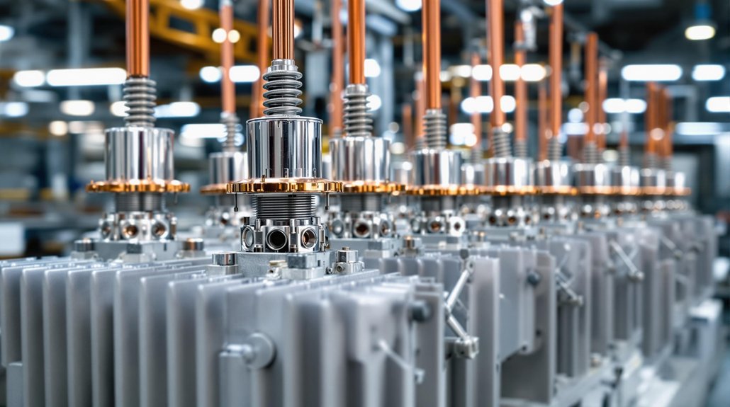
Railway power systems operate across five distinct voltage categories, each demanding specific diode characteristics to guarantee safe and reliable rectification. You’ll encounter 24V-110V DC for auxiliary systems, 750V-1500V DC for traction networks, and 15kV-25kV AC for overhead transmission lines. Each category requires precise current rating calculations to handle peak operational loads.
For traction applications, you must specify diodes with current ratings up to 2,000A while maintaining minimal voltage drop across the junction. EN 50155 compliance mandates your diodes withstand 0.7-1.25× nominal voltage ranges, with transient tolerance reaching 1.4× for ≤100ms periods. High-voltage substations operating at 72kV require surge-rated diodes exceeding 25kA fault current capacity.
Your rectifier design must account for voltage drop limitations—typically ≤1.2V forward drop at rated current—to maintain system efficiency. Temperature derating factors become critical above 70°C, directly affecting both current rating and voltage drop characteristics under sustained railway operations. Power source transitions frequently cause voltage interruptions where diodes must continue rectification despite momentary drops to 0V for periods up to 20ms.
Thermal Management and Environmental Durability Standards
Meeting precise voltage and current specifications means nothing if your diodes can’t survive the punishing thermal and environmental conditions found in railway operations. You must maintain maximum junction temperature below safety thresholds while managing thermal cycling between -40°C and +85°C operational ranges.
Critical thermal management parameters include:
- Thermal resistance (RθJC) quantifying heat transfer from junction to case
- ΨJT parameters enabling rapid Tj estimation via case temperature measurements
- Temperature differential (ΔT) restricted to ≤10K between ambient and initial junction temperature
- Continuous monitoring at ≥1 sample/hour during accelerated aging tests
Environmental durability testing follows IEC 60068-2-67 standards, maintaining 85°C ±2°C with 85% ±5% relative humidity. Advanced thermal management employs phase-change materials and composite structures for enhanced heat dissipation. Dynamic voltage cycling optimizes power loss distribution, while proper heatsink placement determines whether you’ll use RθJC or ΨJT thermal resistance values for system design calculations.
ECPE’s working groups specifically address power semiconductor reliability for railway applications, providing industry consensus on testing protocols and qualification standards. Advanced thermal management employs phase-change materials and composite structures for enhanced heat dissipation. Dynamic voltage cycling optimizes power loss distribution, while proper heatsink placement determines whether you’ll use RθJC or ΨJT thermal resistance values for system design calculations.
Compliance With International Railway Electronics Regulations

You’ll need to navigate three critical regulatory frameworks when implementing high-voltage diodes in railway rectifier systems: EN 50328 standards for railway power supply equipment, IEEE traction power requirements, and IEC certification protocols. These regulations establish mandatory performance thresholds for voltage stability, fault protection, and electromagnetic compatibility that directly impact your diode selection and circuit design decisions. Your compliance strategy must address each framework’s specific testing requirements, as failure to meet any single standard can result in certification rejection and operational safety risks. Railway rectifier systems must also meet EN 50155 requirements for electronic equipment operating conditions, design specifications, and integration protocols to ensure reliable performance across all rail vehicle applications.
EN 50328 Standards
Compliance with EN 50328 establishes the foundation for deploying high-voltage diodes in railway traction power systems, where this European standard specifies mandatory requirements for fixed installations of electronic power converters across railways, tramways, light rail, and underground systems.
Your diode selection must meet stringent performance criteria that directly impact converter efficiency in harsh electrical environments. The standard mandates specific testing protocols for semiconductor devices:
- Type testing under simulated traction system stresses
- Insulation testing for AC/DC interfaces per Table 8 criteria
- Short-circuit protection validation following railway safety standards
- Thermal management assessment under variable load conditions
You’ll need to guarantee your high-voltage diodes demonstrate reliability during dynamic load variations typical in accelerating trains, while maintaining voltage stability and meeting the durable semiconductor material requirements specified for railway traction applications. Adherence to established protocols enhances security by ensuring your diode implementations follow proven railway electronics standards.
IEEE Traction Requirements
Beyond EN 50328’s European framework, IEEE standards provide the international backbone for railway traction electronics, with IEEE 16-2020 establishing non-negotiable performance benchmarks that your high-voltage diodes must satisfy across global rail networks. You’ll encounter stringent voltage tolerances requiring precise semiconductor material specifications and manufacturing tolerances that directly impact diode reliability during operation.
Your designs must withstand extensive testing protocols including surge immunity assessments, temperature cycling from -40°C to +70°C, and mechanical stress evaluations. IEEE 2752-2023 mandates dual grounding systems with protective ground resistance below 1Ω, ensuring safe fault current dispersion. Critical survivability specifications include thermal derating rules and high dv/dt handling capabilities to manage transient voltage spikes from catenary systems while maintaining fail-safe redundancy mechanisms. These requirements provide uniform design specifications that enhance safety and reliability across all railway control apparatus implementations.
IEC Certification Protocols
While IEEE standards establish the operational framework, IEC certification protocols form the regulatory cornerstone that validates your high-voltage diodes against international railway safety and performance mandates. IEC testing encompasses thorough validation through IECEE third-party laboratories that replicate operational conditions including thermal cycling from -40°C to 85°C and vibration stress per IEC61373.
Your certification processes must address four critical validation areas:
- Safety Integrity Levels (SIL) – Components rated SIL 1-4 based on critical functions
- EMC Compliance – Electromagnetic compatibility per EN50121-3-2 standards
- Environmental Durability – Thermal management and insulation coordination validation
- Documentation Requirements – Complete design parameters, safety margins, and test reports
Mutual recognition agreements streamline cross-border approvals, ensuring your diode modules meet international railway electronics regulations while maintaining operational safety margins. IEC TC 9 develops specialized standards for railway and metropolitan transport systems that directly impact diode certification requirements.
Traction Substation Integration and Performance Requirements

As railway systems shift from traditional motor-generator sets to modern thyristor-based rectifiers, traction substations must accommodate increasingly complex integration requirements that directly impact system performance and reliability. You’ll need to configure these systems for continuous operation at high currents while maintaining stable DC output across variable load ranges.
| Parameter | Specification | Critical Impact |
|---|---|---|
| Current Rating | 2,500A continuous | Thermal management |
| THD Compliance | <5% at 80% load | Power quality |
| Power Factor | >0.95 lagging | Grid efficiency |
| Overload Capacity | 150% for 60s | Peak acceleration |
| Voltage Regulation | ±2% no-load to full-load | System stability |
Your traction system integration requires careful performance analysis of rectifier configurations—6, 12, or 24-pulse designs distribute harmonic currents effectively. You must guarantee rectifiers handle regenerative braking energy while maintaining IEEE standards compliance. Natural cooling designs reduce maintenance requirements, but you’ll need fault-tolerant modules for uninterrupted operation during component failures.
Modern installations utilize solid-state thyristor rectifier systems that provide superior reliability and efficiency compared to legacy mercury arc rectifiers and rotary converters.
Locomotive Generator Exciter Protection Systems

When locomotive generators operate under varying load conditions and environmental stresses, exciter protection systems form the critical defense layer that prevents catastrophic failures and guarantees continuous traction power delivery. Your exciter system requires thorough monitoring across multiple parameters to maintain operational integrity.
Temperature and current monitoring prevent output stage component damage through real-time thermal management and load limit enforcement. Short-circuit protection immediately isolates faults, while over-voltage protection guards against destructive spikes. Digital Signal Processor boards execute sophisticated fault detection algorithms that analyze:
- Speed-dependent excitation current variations during acceleration and braking cycles
- Voltage regulation stability under fluctuating load conditions
- Diode failure patterns in excitation circuit configurations
- Temperature thresholds across generator windings and control components
Redundant backup systems, including secondary protection circuits and battery-powered 24V inputs, guarantee continuous operation during primary system failures. Modern excitation devices utilize different excitation profiles to optimize power delivery efficiency during both drive-mode and braking-mode operations. CAN bus integration enables real-time diagnostic data transmission to vehicle computers, facilitating predictive maintenance and reducing unscheduled downtime.
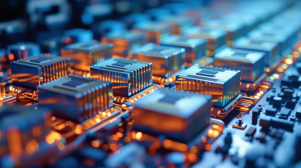
Harmonic Reduction Through Multi-Pulse Rectifier Configurations

You’ll achieve significant harmonic reduction by implementing 12-pulse rectifier configurations, which decrease total harmonic distortion from 40% in 6-pulse systems to approximately 10% through strategic harmonic cancellation. Your phase-shifted transformer design must incorporate 30° staggering between parallel 3-phase circuits to eliminate dominant 5th, 7th, and 11th harmonics that compromise power quality and threaten equipment integrity. This configuration requires precise transformer winding arrangements and auxiliary filtering to meet IEEE 519:2014 compliance standards while maintaining operational safety margins in high-voltage railway applications. Modern railway systems increasingly utilize VSD converter loads in trainsets, which generate distinct harmonic profiles compared to traditional resistive loads and require specialized assessment methodologies for power quality evaluation.
12-Pulse Configuration Benefits
Multi-pulse rectifier configurations deliver substantial harmonic reduction by leveraging phase displacement between transformer secondary windings to cancel specific harmonic orders. You’ll achieve significant harmonic optimization through strategic pulse efficiency implementation, where twelve-pulse systems inherently eliminate characteristic harmonics while eighteen-pulse configurations push THD performance below 3%.
Your pulse configuration selection directly impacts system performance:
- Twelve-pulse systems reduce grid THD to 15.2% under inductive loads
- Eighteen-pulse rectifiers achieve ~7.36% THD without additional filtering
- Multi-pulse designs minimize DC ripple content and voltage fluctuations
- Active injection circuits enhance lower-pulse system mitigation capabilities
You must balance manufacturing complexity against harmonic performance when selecting pulse counts. Higher configurations require specialized transformer windings but deliver superior grid compliance, reducing your dependency on extensive filtering systems for railway applications. The general equation h = n * (p +/- 1) defines the relationship between pulse number and resulting harmonic frequencies in multi-pulse converter systems.
Phase-Shifted Transformer Design
Phase-shifted transformer design achieves harmonic cancellation through precise angular displacement between multiple rectifier units, where Y-Δ dual-transformer configurations generate the critical 15° phase differences required for 24-pulse rectification systems. You’ll need to implement dual-transformer designs with Y-Δ and Δ-Y connections to create these exact phase shifts. Primary side current management through transformer impedance guarantees proper flux balance while maintaining safety standards for high-voltage operations. Phase shift control loops dynamically adjust secondary voltages to counteract harmonic injection, reducing 5th and 7th order components effectively. Epoxy resin construction enhances thermal stability in your transformer cores, while shielded insulation safely handles 10kV to 35kV inputs. This configuration delivers compliant THD reduction for modern rail applications.
Maintenance Optimization and Overload Capacity Features
When implementing maintenance optimization for high-voltage railway rectifier diodes, you must establish systematic protocols that integrate electrical continuity testing, thermal imaging diagnostics, and calibrated DVOM verification procedures to ascertain operational reliability.
Your maintenance techniques require bi-annual scheduling to prevent critical failures. Implement visual inspections for physical damage detection, while thermal imaging identifies heat distribution anomalies indicating internal defects. Temperature monitoring through thermal sensors tracks operating thresholds, preventing catastrophic overheating.
For overload protection, you’ll need these critical features:
- Bidirectional power flow support for regenerative braking energy capture
- Surge protection circuits blocking voltage spikes exceeding safe parameters
- Modular redundancy preventing cascading failures during overload conditions
- Optimized reverse recovery time enabling rapid current switching
Modular multi-cell designs replace thyristor-based systems, enhancing efficiency. Regular component replacements address aging before failure occurs. Airflow optimization ensures proper heat dissipation in high-voltage environments, while infrared monitoring provides real-time thermal diagnostics for early fault detection.
You may also like to read – How to Select EMD Traction Rectifier Diodes
Frequently Asked Questions
What Are the Typical Costs for Replacing High-Voltage Diodes in Railway Systems?
You’ll face diode pricing of $125 per HVD 1005 board for 34-40 kV applications. Your replacement budget must account for substation spacing—25 kV systems need boards every 32 km versus 50 kV systems every 64 km. You’re looking at higher upfront costs but reduced deployment density with higher voltages. Plan for MOV-protected boards to extend service life and minimize unplanned replacements in your maintenance budget.
How Long Do Railway Rectifier Diodes Typically Last Before Requiring Replacement?
Like mechanical clockwork, you’ll find railway rectifier diodes typically last 15-25 years under normal operating conditions. Key diode longevity factors include maintaining junction temperatures below 125°C and proper thermal management. You should monitor performance degradation indicators such as increased reverse leakage current exceeding 10µA and forward voltage drops deviating beyond ±0.1V specifications. Regular testing every 2-3 years guarantees safety compliance.
Can Existing AC Railway Systems Be Retrofitted With Modern Diode Rectifiers?
You’ll face significant retrofitting challenges when upgrading AC railway systems with modern diode rectifiers, requiring careful voltage compatibility analysis and thermal management integration. Modern diode efficiency improvements of 15-25% justify conversion costs, but you must evaluate existing infrastructure constraints, cooling system adequacy, and protective relay coordination. You’ll need phased implementation strategies to minimize service disruptions while ensuring safety compliance with updated rectifier specifications and harmonic distortion limits.
What Backup Power Options Exist if Primary Rectifier Diodes Fail Unexpectedly?
Like medieval castle fortifications protecting against siege, you’ll need redundant systems when rectifier diodes fail catastrophically. Deploy parallel rectifier banks with automatic switchover capabilities, ensuring 99.9% availability during primary failures. Install power storage via UPS batteries providing 2-8 hours autonomy for critical signaling loads. Implement load-shedding protocols prioritizing safety systems over passenger amenities. Hot-swappable modular designs enable rapid maintenance without complete shutdown, maintaining operational continuity during component replacement procedures.
Are There Specific Safety Procedures for Handling High-Voltage Railway Diodes During Maintenance?
You’ll follow strict safety protocols when handling high-voltage railway diodes. Wear insulated PPE and obtain Electrical Permits before starting work. De-energize systems through proper disconnect procedures, then conduct visual inspections for cracks or corrosion. Apply voltmeter tests to verify grounding effectiveness and use multimeter shunt measurements for leakage quantification. These maintenance guidelines require authorized traction lineman certification and documentation of all test results for compliance tracking.