
You start by tracing numbered ports (supply 11/12, deliveries 21–24, controls 41/42) and matching DIN/WABCO symbols to pneumatic or hydraulic line styles; follow solid lines for hydraulic, dashed for air, and arrows for flow direction. Identify relays, charging/check valves and load‑sensing diaphragms, then map solenoid coils to ECU outputs (I/II behaviors: increase/reduce/hold). Confirm reservoir, protection and pressure reducing settings against schematic values. Continue and you’ll uncover component tests, diagnostics and precise valve sequencing.
Key Takeaways
- Identify port numbers first (11/12 supply, 21–24 delivery, 41/42 control, vents 3/31) to trace flow paths.
- Distinguish pneumatic (dashed/double lines, tanks, compressors) from hydraulic (solid lines, accumulators) by line and symbol style.
- Map commercial port labels (21–24, 42–43) to locomotive-specific tags and follow OEM markings when they conflict.
- Read valve symbols for normal state, spring return, and solenoid positions to determine charge, hold, and release behavior.
- Use diaphragm/piston and check-valve symbols to find load-sensing, anti-compounding, and backflow prevention circuits.
Overview of WABCO Locomotive Valve Assembly Symbols

Although available diagrams focus on WABCO commercial vehicle ABS components rather than locomotive-specific parts, you can still use the same symbol conventions to interpret basic valve functions. You’ll rely on familiar port configuration symbols—NPT fractional sizes (¼”, 3/8″, ½”) for supply, control, delivery and exhaust—to map connections on locomotive schematics where explicit locomotive iconography is absent. Modulator valve assembly designations (left/right, single, dual, external, ECU-integrated) let you infer wheel-specific and integrated functions even if locomotive-specific drawings aren’t provided.
ABS system configuration symbols (2S/1M through 4S/4M) guide you in understanding sensor-to-modulator relationships. Relay, flat twin, ABS relay and quick release valve symbols communicate distribution and exhaust roles. ECU interface markings—power, sensor inputs (C–F), diagnostic, GIO—help you locate electronic integration points. Recognize that this approach reflects a historical evolution of WABCO diagram standards: commercial symbols serve as a transferable baseline for interpreting locomotive valve assemblies.
Port Numbering and Identification on Locomotive Brake Valves
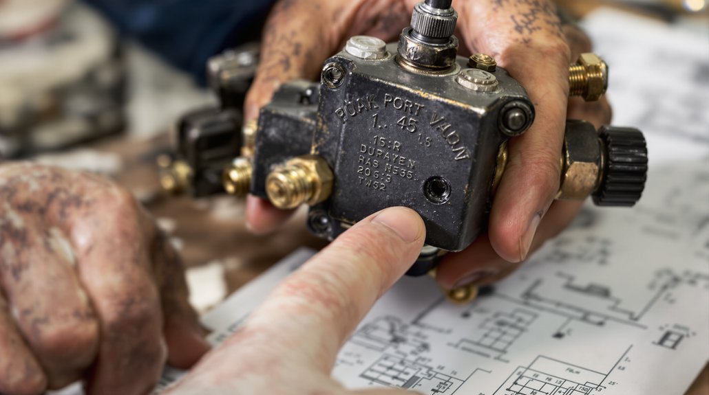
When you examine WABCO locomotive brake-valve schematics, port numbering serves as the primary key for tracing supply, control, delivery and exhaust paths across assemblies, but available documentation often borrows commercial-vehicle conventions rather than a standardized locomotive schema.
You’ll rely on port mapping to follow air flow and on valve tagging to correlate physical ports with diagram symbols. Because locomotive-specific data is limited, expect to see commercial-port references (e.g., 21–24, 42–43) repurposed; verify connector coding on drawings and in the valve’s service manual. Use service numbering consistently: supply, control, delivery, exhaust. Confirm any ambiguous labels against component part numbers and wiring/air-hose layouts.
| Label Type | Typical Use |
|---|---|
| Port mapping | Flow tracing |
| Connector coding | Electrical/pneumatic interfaces |
| Service numbering | Functional grouping |
| Valve tagging | Physical ID/reference |
When documentation conflicts, prioritize OEM manuals and on-equipment markings over generic commercial references.
Interpreting Relay and Relay Emergency Valve Diagrams
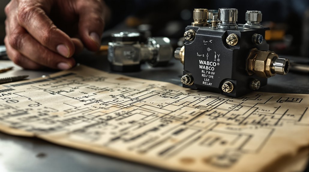
Because relay and relay-emergency valve diagrams use standardized pneumatic symbols and numbered ports to define flow, you’ll need to map each symbol to its functional port (1, 2, 4, 11, 12, etc.) before tracing supply, control, delivery and exhaust paths. Start by identifying DIN 74 253 and DIN ISO 1219 symbols, then tag supply ports (11/12), control ports (41/42), and delivery ports (21–24). Follow the charging valve and check valves to verify backflow prevention and emergency sequencing logic.
Note electromagnetic actuation symbols for solenoid relay integrations and where armature-controlled bores enable C→D flow. For spring brake systems, confirm anti-compounding links and dual overflow routing to secondary ports. Check connector sizes and plug unused ports per specifications. Evaluate pressure balancing between reservoirs, delivery chambers and release valves to confirm correct charging threshold and safety valve limits. You’ll trace functional paths decisively, isolating charging, service, emergency and exhaust behaviors for accurate troubleshooting and verification.
Reading Load Sensing Valve Components and Flow Paths
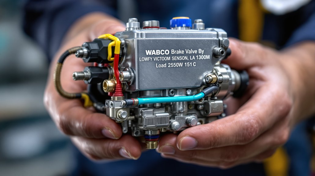
You’ll inspect the guide sleeve and cam first, since their geometry directly sets cam rotation and linkage travel that translate suspension movement into valve actuation. Then check diaphragms and pistons for wear or distortion, because their sealing and movement control proportional pressure output and response to load changes. Finally trace port flow and chamber passages on the diagram to confirm correct routing between supply, relay, quick-release and trailer circuits and to identify where pressure is modulated or bled. The component also has specific physical specs, including a size 313 x 154 x 124 mm that can affect mounting and routing.
Guide Sleeve and Cam
Start by locating the guide sleeve and cam assembly between the relay valve and brake chambers, since the sleeve channels airflow from the relay (pos. 11) and the cam/guide interface directly transmits mechanical input from the knuckle joint (pos. 19) to the load sensing valve (pos. 18). You’ll inspect M16 x 1.5 threaded guide sleeves, push-rod engagement, and bolt spacing (76.2 mm) to verify correct alignment and guide sleeve maintenance intervals.
Read cam type designation and clamp band angle (-45°) to confirm installation. Note return spring force (100 N), max operating pressure (8.5 bar) and output force (6500 N) when evaluating performance. Track cam wear patterns at contact faces and boot integrity to prevent contamination affecting flow through quick release and check valve paths. Also check compatible compressor-related parts, such as pistons and rings, to ensure the overall system meets OEM-equivalent standards.
Diaphragms and Pistons
Examine the diaphragms and pistons as a coordinated pressure-to-mechanical interface that directly controls load-compensated brake output: pilot pressure from the air suspension bellows (ports 41/42) acts on dual pilot pistons (m and k) to shift the guide sleeve (i) and cam (h) against spring (z), while main control piston (d) is driven by relay-supplied brake air via port 1 to sequence inlet (c) and outlet (e) actions; diaphragm (f) in chamber B then transmits the resulting pressure to downstream ports 2, and built-in features — the test piston (n) for port 43 diagnostics and the rubber pressure-block (p) engaging tappet (r) above 0.8 bar — guarantee you can verify operation and lock the reduction ratio during dynamic load events.
Maintain attention to diaphragm sizing for correct force translation and piston balancing to avoid asymmetric valve response. The valve is designed to operate reliably within a typical inlet pressure of 10.0 bar.
Port Flow and Chambers
Having inspected how diaphragms and pistons convert pilot pressures into mechanical motion, we now map how those motions direct air through the valve’s ports and chambers. You’ll trace reservoir supply from ports 11/12 into the body, then follow delivery routing to 21–24; primary and secondary priority charging goes to 21 and 22, while 23 and 24 serve auxiliary functions. Control ports 41/42 and 43 modulate service and park brake inputs for spring actuation. Inside the valve, chamber sequencing governs which passages open or block as pressures reach thresholds, preventing anti‑compounding. Monitor reservoir and auxiliary pressures, low‑pressure switches, and stop‑light feedback on delivery ports. Plug unused ports in reduced configurations. Understand these flows to diagnose load‑sensing and relay behaviors accurately.
Solenoid and Electronic Control Elements in Brake Schematics
Understand how solenoids and the ECU coordinate to modulate brake pressure: solenoid valves I and II act on inlet, outlet and pilot passages so that, in milliseconds, the ECU can increase (both solenoids de-energized), reduce (solenoid I energized to close the vent and open the pilot chamber) or hold pressure (pulse signals closing vents) in brake cylinders, with wiring, sensor extensions and diagnostic lamps shown in schematics to reflect electrical and pneumatic integration.
You’ll read the ECU as the central control node: ECU mapping in diagrams links it to solenoid cables, sensor extensions and warning lamps. Solenoid diagnostics relies on tracing these connections, verifying coil continuity, driver outputs and response times. Note component numbering (solenoids often labeled 33) and material numbers in wiring views for serviceability. Interpret modulator valves, 3/2 adapters and relay interfaces by port numbering (Port 1, Port 22) to confirm inlet, outlet and vent paths. Use the schematic to correlate electrical actuations with immediate pneumatic valve states. WABCO parts such as ABS modulator valves are commonly listed as in stock.
Pressure Reduction, Release, and Adjustment Symbols
When you read brake schematics, pressure reduction, release, and adjustment symbols tell you exactly how downstream pressure is set, relieved, or locked relative to upstream sources. You’ll recognize pressure limiting symbols showing ports 1 and 2 with an internal spring calibration that defines relief thresholds and locking lines. Parenthetical numbers like (3) mark available fixed settings; most valves offer two standard fixed settings and hand selector variants let you switch between them without hardware changes.
Release valve portrayals—often 2-1 with a port 4 reference—show normally closed or open states that determine release timing and emergency release paths in two-line systems. Pressure reducing valve symbols indicate constant downstream regulation despite upstream swings and identify specific parts used in diagrams. Triple protection and load-sensing integrations appear as additional diaphragms and non-return elements controlling crossflow and predominance. Read the control lines and port IDs to verify adjustable predominance, locking mechanisms, and correct application of fixed settings for safe braking performance.
Hydraulic Vs Pneumatic Circuit Representations in WABCO Systems
When you compare WABCO hydraulic and pneumatic diagrams you’ll first notice distinct symbol sets: hydraulic paths use solid lines, reservoir and accumulator symbols, and rectangular modulator blocks with integrated solenoid valves. Pneumatic conventions employ dashed or double lines, air tanks, compressor and dryer symbols, and triangular or diamond-shaped control valves with spring returns. Learn to read line style, valve shape, and energy-storage symbols to quickly tell which system and control logic you’re inspecting.
Hydraulic Circuit Symbols
Several core symbols distinguish hydraulic from pneumatic circuit representations in WABCO diagrams, and you’ll need to recognize them to read modulator and valve assemblies correctly. You’ll rely on hydraulic symbols and schematic legends to identify inlet and outlet valves, DIF valves with positive/negative terminals, and integrated ABS valve units. Flow arrows show pressure direction through pump motors, accumulators, and pressure supply valves; valve actuation is depicted with solenoid coils and actuator positions mapped to pin numbers. ECU connector views link electronic commands to specific solenoid valves via multi-pin layouts (14–18 up to 47 pins) and NOT USED markings. Sensor and ground references, twisted-pair paths, and battery/ignition feeds are shown to clarify hydraulic versus electronic integration.
Pneumatic Circuit Conventions
Although both use standardized symbols, pneumatic circuit conventions in WABCO diagrams prioritize air-specific components—compressors, air dryers, reservoirs, pressure switches, and multi-circuit protection valves—so you’ll read port numbers, pressure thresholds, and venting paths differently than in hydraulic schematics. You’ll recognize DIN ISO 5599 port numbering: port 1 compressor input, 21/22 service circuits, 23 trailer, 24 accessory, 25 parking, 26 clutch, and vents at 3 and 31. Diagrams show Type I closed positions and Type II open-over-pressure behavior with diaphragm versus spring notation; protection valve opening thresholds are explicit for safety. Use signal mapping to trace ECU/RCU connections and pressure transducers at 6.X. Focus on valve sequencing and reservoir maintenance to maintain minimum service/trailer pressures and proper circuit function.
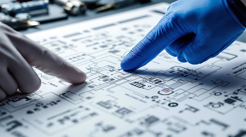
Diagnostic and Test Connection Points on Locomotive Valve Diagrams
Starting from the diagnostic screen, you’ll access and verify every test and connection point for the brake valve system using the component test menu, diagnostic ports, sensor inputs, pressure taps, and control-signal terminals. Use the pull-down component test interface to select individual valve elements, hit Send for manual actuation, and watch the status box for real-time activation feedback; Close exits the test while keeping the diagnostic link.
Connect your tool to SAE J1587 port A for fault codes and to SAE J1939 CAN high/low for advanced messaging; assure proper diagnostic grounding and ignition power before probing. Verify wheel speed sensors at FL/FR/RL/RR with the ECU orientation set and green background confirmation while rotating wheels at 1/2 rev/s. Probe pressure taps: below piston, equalizing reservoir, Service I/II, Circuit III, and check-valve points. Test valve control signals—two-wire trainline signaling, brake light, solenoid supply/ground, parking brake switch, and ATC valve—using twisted-pair wiring for reliable traces.
You may also like to read: How to Fix Locomotive Air System Gasket Problems
Frequently Asked Questions
What Maintenance Schedule Is Recommended for Valve Components Shown in Diagrams?
Think of routine care as considerate stewardship: you should perform monthly inspections of valve components, checking for leaks, proper drain function, and pop-off pressures. Replace leaking manual drains immediately; repair automatic drains if they fail. Conduct pressure stabilization and leak tests during service. Schedule annual overhauls to replace worn safety valves, IR-2 units exceeding leakage limits, and to inspect relay, quick-release, and foot brake valves per OEM guidance and safety protocols.
How Do Diagram Conventions Differ Between WABCO Model Years?
You’ll see model-year differences driven by symbol evolution and notation standardization: older diagrams use DIN 74 253 symbols and simpler color keys, while newer ones adopt SAE J447 conventions, expanded color coding, and updated valve symbols (inversion, quick release, anti-compounding). You’ll also notice added circuit labels for triple protection and ABS, revised numbering for semi-trailer layouts, and clearer reservoir/control line distinctions reflecting regulatory and safety-driven updates.
Which Spare Parts Correspond to Port Numbers in Schematics?
Port mapping ties schematic ports to part identification: Port 1 → primary supply tubing assembly (use 5/8″ nylon), Ports 2/4 → service/control fittings (3/8″ or 1/4″ NPTF variants), Ports 11/21 → TCV breakaway modules, Ports 22/42/43 → TCV output/backup/handbrake components. Use diagram legends to confirm exact part numbers (400 500 101–106 series) and specified seal materials (SAE Teflon tape or paste sealant) for correct installation.
Are There Torque Specifications for Mounting Flange and Fitting Connections?
Yes — you’ll find specified fasteners torque for mounting flange and fitting connections. Think of it as giving each joint the right handshake. Use 18 lb‑ft (24 N·m) for mounting bolts, 29.8–33.9 N·m with Loctite 242 for cap screws, and 54.2–67.8 N·m where housings and plugs mate. Apply sealing compounds per procedure, follow torque patterns, finger‑tight then final values, and record depths to assure proper sealing and performance.
How to Verify Wiring Pinouts for ABS Solenoid Connectors?
You verify wiring pinouts for ABS solenoid connectors by comparing pin mapping to connector labelling, then performing voltage, resistance and continuity tests. Reference the OEM pin mapping chart, check connector labelling for pin numbers/colors, measure supply voltage with ignition on (10–14V where required), ground continuity between specified pins, and confirm solenoid resistance per spec. Use jumper tests to energize relays and observe pump/solenoid activation for functional verification.
You may like to read: Wabco Brakes 2