
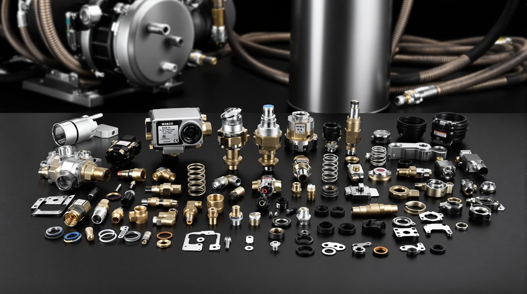
You’ll find WABCO foot brake valve parts labeled by function and part number—quick release, two‑way, check, relay, load‑sensing, and multi‑circuit valves—each with specified ports, thread types (M16×1.5, NPTF), and pressure limits (service to ~8.5 bar; max ~10–10.4 bar). Mounting, temperature, and actuator interfaces are standardized; torque, purge, and dryer routing practices are critical. Inspect diaphragms, springs, and purge cycles for serviceability. Continue for component IDs, specs, and installation best practices.
Key Takeaways
- Identify valves by part numbers (e.g., 4613180360, 4613320000, 961-899-006-0) and matching temperature/pressure ratings.
- Match valve function to type: relay, quick‑release, load‑sensing, check, dual/quad circuit, or trailer control valves.
- Note mounting and connection specs: M16×1.5 ports, ITT Cannon 4‑pin electrical plug, and 3×Ø9.0 mm fastener pattern.
- Trace air routing: compressor → unloader → dryer → valves, using specified 1/2‑inch NPTF fittings and recommended hose types.
- Inspect physical indicators: predominance setting, crack pressure, operating range (−40°C to +80°C or +110°C), and purge/drain placement.
Overview of WABCO Foot Brake Valve Models and Specifications
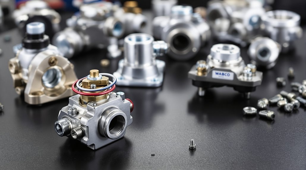
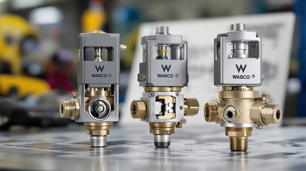
Several WABCO foot brake valve models cover the range of commercial-vehicle braking needs, and you’ll find each specified for distinct operating, mounting, and connection requirements. You’ll identify models by part numbers—4613180360 (OE-spec premium), 4613320000 (standard), 4613180490 (original construction for trucks/buses), 961-899-006-0 (high-demand/back-order), and 4613154970 (GTIN/UPC tracked)—and use those IDs to match specs.
You’ll note operating limits: max pressures up to 10.0–10.40 bar, predominance setting 0.30 bar on select units, and temperature ratings from −40°C to +80°C (extended to +110°C on 961-899-006-0). You’ll assess physical and mounting data: sizes, weights, 3×Ø9.0 mm mounting holes spaced 80×180 mm, and compact variants for confined spaces. You’ll verify connections: ITT Cannon 4-pin electrical interface, M16×1.5 port threads, flap exhaust, and specified actuation/valve components. Pay attention to pedal ergonomics and valve ergonomics when selecting for driver interface and serviceability. The assembly typically mounts with three fasteners and has a calculated volume of 15.0535 dm³.
Air Compressor and Air Dryer Integration With Valve Assemblies
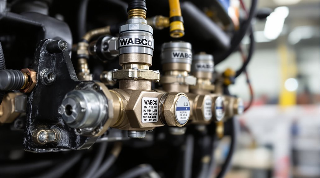
You’ll route the SS318 compressor discharge through the unloader valve into the air dryer so pressure is held between 7.2–8.1 bar before reaching valve assemblies. Position the dryer unloader and venting to expel moisture upstream of the quadruple-circuit protection valve to prevent water carryover. Use cartridge-style protection and strategic plumbing (drains, traps, and check valves) to keep moisture out of brake chambers and downstream valves. The system is designed to match or exceed OEM specifications of the Automann 170.AC535300 compressor.
Compressor-To-Valve Routing
When you route the compressor discharge to the valve assembly, connect the compressor discharge port to the Econ valve inlet with a 1/2‑inch‑14 NPTF female fitting and run the delivery line from the Econ valve outlet (1/2‑inch NPTF male) to the air dryer inlet marked “1.” You’ll use #10 or #12 stainless braided Teflon hose for precision hose routing, and 1/2‑ or 5/8‑inch braided fabric for primary dryer connections. Observe compressor alignment and cylinder head valve positioning during installation.
Tie the governor unloader line to dryer control port “4” via a tee fitting. Torque head bolts per spec and verify alignment sleeves and notched pins. Keep dryer compactly mounted near the compressor, maintain clearance for fittings, and inspect all fittings for leak-free sealing before service. Always ensure operators follow basic safety practices and use proper tools before starting any work.
| Item | Spec |
|---|---|
| Delivery hose | #10/#12 |
| Fittings | 1/2‑inch NPTF |
Dryer Unloader Placement
For proper purge cycling, mount the air dryer lower than the compressor and within 30° of true vertical so condensate drains into the dryer and the desiccant cartridge sits at the top for effective regeneration. You’ll route the compressor control purge port to the dryer purge valve via a dedicated unloader line; this unloader routing expels collected moisture and contaminants during unload cycles.
Make sure desiccant orientation is maintained with the cartridge at the top and allow two inches clearance above for service. Avoid line low points or water traps before or after the dryer. Position one-way check and pressure-controlled check valves downstream to prevent backflow. Maintain minimum 12 inches clearance from heat sources and provide airflow without direct splash exposure for reliable operation. The purge valve should be rebuilt periodically using OEM Wabco/Meritor parts to ensure sealing and prevent leaks.
Moisture Prevention Strategies
Proper dryer placement sets the stage for keeping moisture out of valve assemblies, but you also need coordinated compressor-to-dryer integration and filtration to stop water, oil, and aerosols from reaching control valves. You’ll route compressed air through the desiccant cartridge during build‑up so the desiccant bed removes water vapor before reservoirs and valves. The Air System Protector adds coalescing filtration at the cartridge base to trap oil and aerosols after desiccant processing, preventing corrosion and freezing. Regeneration purge bursts expel collected moisture and oil from the cartridge, restoring capacity.
- Assure compressor discharge feeds dryer inlet at proper temperature and flow
- Use WABCO ASP cartridges for two‑stage desiccant + coalescing filtration
- Schedule cartridge replacement per 2‑year service life
- Verify purge cycle function and drain performance
- Check for a consistent purge burst during compressor cut‑out to confirm the purge valve is functioning
Dual and Quadruple Circuit Valve Functions in Locomotive Systems
Although detailed locomotive-specific references weren’t available in the search results, you should understand that dual and quadruple circuit valves in traction applications serve to segregate and manage multiple independent air or pneumatic brake circuits—providing redundancy, selective control of distinct axle sets or consist segments, and prioritized emergency feed paths—so a failure in one circuit doesn’t incapacitate the entire braking system.
You’ll apply principles from commercial dual-circuit valves: separate inlet and delivery ports, relay action to minimize lag over long piping, and inversion or anti-compounding features to safeguard spring-applied parking brakes. In practice, quadruple arrangements extend redundancy and zone isolation for multiple consists or trucksets, enhancing locomotive redundancy and enabling graded emergency modulation across zones.
Installation demands strict port identification, correct reservoir routing, and pressure verification at rated 105–130 psi equivalents. During maintenance, you’ll verify diaphragm integrity, relay timing, and emergency valve switching to guarantee selective circuit isolation, reliable emergency feed, and controlled modulation under fault conditions.
Load-Sensing and Relay Valve Roles for Brake Pressure Control
When load changes, the load-sensing valve automatically modulates service brake pressure so you get proportional braking force without driver intervention. You rely on load compensation dynamics: pilot pressure from air suspension bellows moves internal pistons and a guide sleeve with cam actuation sequencing against spring tension to set the regulating position as chassis-to-axle distance varies. The valve establishes frictional connection above 0.8 bar to maintain reduction ratios and prevent overbraking.
- Relay emergency valve supplies compressed air via port 1 to pressurize pistons and control outlets.
- Load-sensing pilot lines link load-empty and load-sensing valves to adjust front axle pressure.
- Trailer control and adapter valves route service air and reduce pressure in partial-braking ranges.
- ABS and relay valves receive actuation from the load-sensing valve for distribution to brake chambers.
Install vertically with vent down, use setscrews and specified linkages; test via port 43 to verify piston movement and calibration.
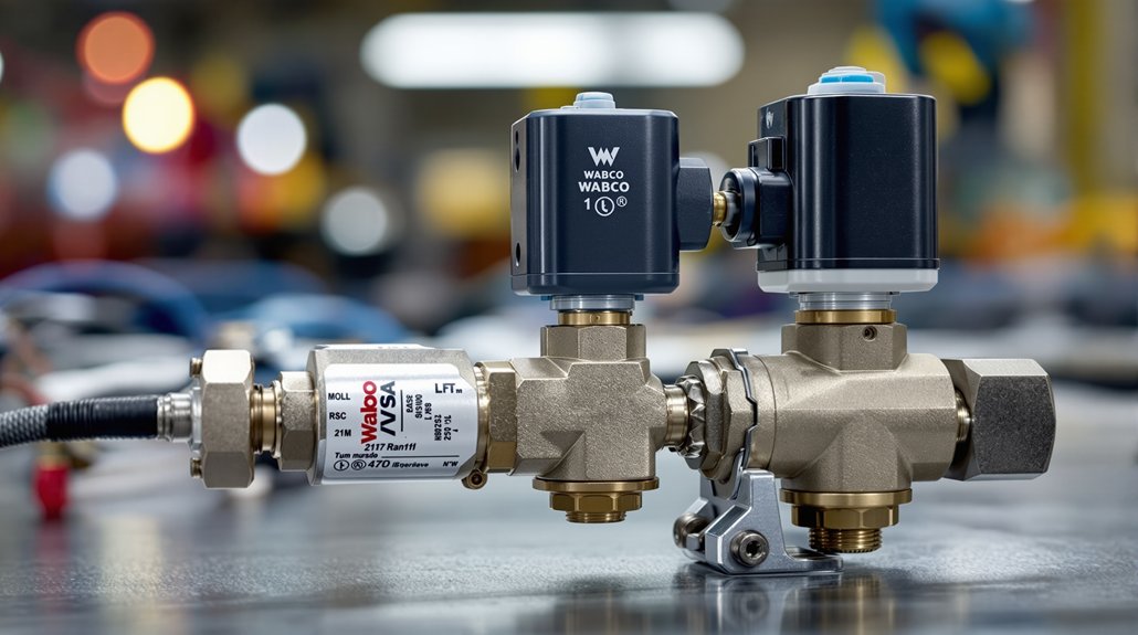
Quick Release, Two-Way, and Check Valve Operations
Having covered how load-sensing and relay valves regulate brake pressure with changing chassis load, we’ll now examine quick release, two-way, and check valves that execute rapid exhaust, service-line switching, and one-way protection functions in the brake circuit. You’ll use quick release valves to dump delivery-port air to atmosphere quickly; the exhaust port and diaphragm motion determine on, off, and hold states. Check diaphragm calibration during quick release diagnostics to confirm downward sealing of the exhaust port and correct spring-diaphragm neutral positioning.
Two-way valves let you alternate a service line between pressurized Port 1 and exhaust via Port 2, using a cam-actuated piston and return spring to lock pressure or exhaust positions. Double check and check valves prevent compounding between supply and balance ports, enforce crack-pressure specs, and protect dual circuits. Verify port configurations, crack pressure ratings, and spring loads so release timing and one-way protection preserve brake actuator performance without introducing force multiplication. The engine-driven compressor supplies stored air to a reservoir, ensuring compressed air supply for all braking operations.
Spring Brake, TRISTOP, and UNISTOP Actuator Interfaces
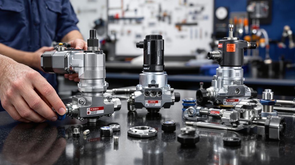
Start by locating the spring brake actuator’s key interfaces: diaphragm assemblies, push‑rod/clevis connections, boot seals, and mounting hardware — these determine how TRISTOP and UNISTOP cylinders transmit service and parking forces. You’ll inspect the diaphragm assemblies (part 8971205254) for diaphragm wear and check boot assemblies (8977510104, 8977548862) for sealing integrity. TRISTOP dual‑chamber designs separate service and parking functions; UNISTOP uses a single chamber, so your diagnostic focus changes accordingly.
Locate diaphragm, push‑rod/clevis, boot seals and mounting hardware; inspect diaphragms and boots, noting TRISTOP vs UNISTOP differences.
- Verify clevis alignment and 14mm clevis pin seating for correct push‑rod articulation.
- Confirm Ball R8 push‑rod threading and 15mm engagement for disc brake interfaces.
- Check hexagon thin nuts (DIN439‑2‑BM16x1.5) and M16×1.5 bolt threads for secure yoke retention.
- Assess compression spring assemblies (8960801704) and return‑spring force (220 N) for proper release characteristics.
Measure actuator dimensions and pressures against OEM specs to confirm fit and function; note that the Wabco 9254813760 has a Max. operating pressure of 10.2/8.5 bar.
Mounting, Pressure Ratings, and Environmental Specifications
When mounting the valve assembly you’ll follow specific fastener, bracket, and hole‑pattern requirements to guarantee structural integrity and prevent galvanic corrosion. You’ll verify pressure and temperature ratings against TABLE 1, use the shim system to set service pressures, and seal NPTF fittings per thread‑seal instructions to protect internal components. Pay attention to torque values and port orientations so mounting and environmental protections don’t compromise performance or serviceability.
Mounting and Fasteners
Although precise torque values and surface tolerances might seem minor, they determine long‑term valve integrity and system safety, so you should follow the specified mounting and fastener requirements exactly. You’ll apply corrosion resistant coatings where dissimilar metals meet, use thin barriers to prevent galvanic attack, and verify housing alignment to confirm o‑ring seating. Follow the fastener torque sequence and specified values: cap screws 29.8–33.9 N·m with Loctite 242, end plugs 47.5–54.2 N·m, 8mm hardware 20 ±3 N·m, and 3/8″ Grade 8 bolts with prevailing‑torque nuts for ECU/modulator mounts. Maintain surface flatness within 0.25 mm, orient exhausts downward within 30°, and keep mounting proximity to served components to minimize air line length.
- Use schedule 80 hex nipples for air tank connections
- Seal pipe threads per SAE/DOT standards
- Protect sensor connectors with caps
- Avoid vise clamping during nipple installation
Pressure and Temperature Ratings
Because component longevity and system safety depend on strict adherence to specified limits, you must mount and operate valve assemblies within defined pressure and temperature ratings. Mount to the 80 ± 10 mm tolerance, use M22 x 1.5 thread depth 12 mm, and respect push rod pivot 3° tolerance to prevent misalignment under load. Maintain service pressure up to 8.5 bar; brake chambers max at 10 bar.
Governor valves regulate supply at 110–130 PSI. Temperature range is −40°C to +80°C for valve bodies and O‑rings; activate anti‑freeze below +5°C. Design considers ambient calibration and thermal cycling for repeatable performance. Filtration, O‑rings, and relay valve displacement torque specs preserve pressure integrity. Follow these ratings to assure safe, compliant operation in commercial vehicle environments.
Maintenance Checks: Leak Inspection, Fastener Torque, and Safety Switches
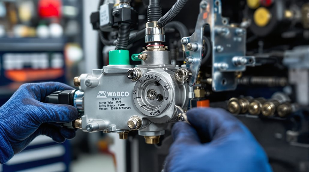
Start by inspecting the system for leaks, then verify fastener torque and the operation of all safety switches to make certain the valve assembly meets service and regulatory criteria. You’ll perform leak detection at all joints, seals and ports using approved methods (soap solution, electronic sniffer) while pressurizing circuits to spec. Check safety valves per the provided fact: safety valves require inspection and functional test. Confirm switch calibration against manufacturer tolerances and exercise switches under load. Torque all fasteners to published values in a controlled sequence and record readings.
Inspect for leaks, verify torques, and test safety valves and switches—document findings and tag any nonconformances.
- Verify no audible or visible leaks at fittings, diaphragms, and valve bodies.
- Torque fasteners to spec using calibrated tools and follow tightening sequence.
- Test safety valves for setpoint and hysteresis; document results.
- Calibrate and functional-test switches; confirm electrical continuity under actuation.
You’ll log all findings, tag nonconforming items for repair, and follow regulatory documentation requirements before returning the assembly to service.
You may also like to read: How to Read WABCO Brake Valve Diagrams
Frequently Asked Questions
Are Replacement Parts Covered by Warranty and for How Long?
Promptly: you’re protected — parts-only warranty duration typically runs one year for aftermarket replacements, while select programs give three years/300,000 miles with parts and labor. You should note coverage exclusions for misuse, accidents, improper maintenance, overloads, and specified engine/compressor exceptions. You’ll need to follow claim procedures, retain claimed parts for inspection, and work through authorized channels to confirm eligibility before repairs or reimbursement.
Can Aftermarket Valves Affect Vehicle Insurance or Regulatory Compliance?
Yes — aftermarket valves can affect insurance implications and create compliance risks. You’ll likely see higher premiums, reduced settlements, or denied diminished-value claims if insurers deem parts inferior. Regulators in some states require disclosure and let you demand OEM equivalents; failing that can void coverage or trigger liability if failures cause accidents. You should document approvals, follow state rules, and notify your insurer to minimize financial and legal exposure.
What Are Recommended Vendors for OEM WABCO Replacement Parts?
You should source OEM WABCO replacements from authorized ZF/WABCO channels like Bosch Rexroth distributors and Meritor Wabco partners. Use ZF Aftermarket-authorized dealers, Precision Transmission, HTD Parts, and Maxim Truck & Trailer for verified parts, VIN-based fitment, and factory testing documentation. Confirm authenticity via material numbers and ZF/WABCO cross-references, request warranty papers, and contact WABCO Customer Care for validation before buying.
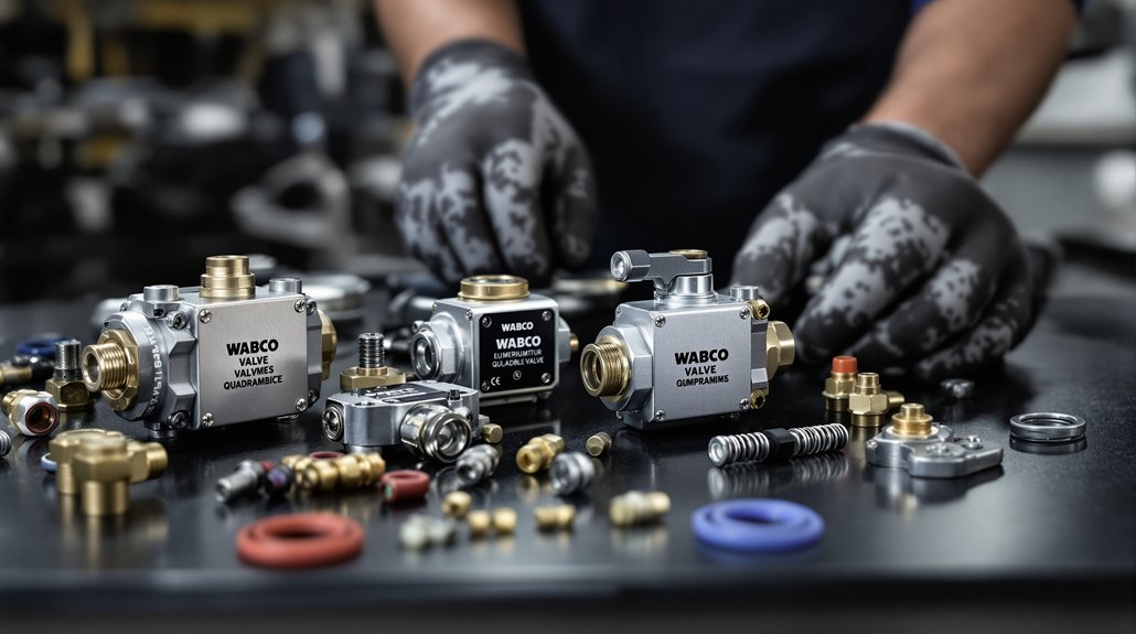
Is Specialized Training Required to Service WABCO Valve Assemblies?
Yes — you’ll need specialized training. Like a telegram’s urgency, you’ll pursue technical certification and attend hands on workshops to safely service WABCO valve assemblies. You’ll gain diagnostics, parameterization, and component-replacement skills, plus PIN access for diagnostic software. This guarantees compliance, accuracy, and reduced downtime. Employers expect documented competency, so complete accredited courses and practical sessions to meet workshop, fleet, and regulatory requirements.
How Do Software Updates Affect ASR or Electronic Valve Functions?
Software updates can change ASR and electronic valve functions by altering software compatibility and introducing feature deprecation. You’ll get enhanced diagnostics, new control features (e.g., RSC, engine CAN control) or stricter fault handling, but incompatible firmware or deprecated features can disable certain valve behaviors or in-cab displays. You must verify update files, baud rates and PIN access; otherwise functions may be reduced, locked or require reconfiguration to restore expected operation.