What Are Common Failure Symptoms of Locomotive Turbo Soak Back Pump 40182032?

What Are Common Failure Symptoms of Locomotive Turbo Soak Back Pump 40182032?

If your locomotive turbo soak back pump 40182032 is starting to fail, the most frustrating issue is usually what happens right after shutdown or during the next startup: the turbo does not receive proper post-shutdown oil circulation, heat remains trapped in the turbocharger, and crews or maintenance teams begin seeing rising wear, delayed spool-up, abnormal turbo noise, and inconsistent lubrication-related alarms.

In locomotive service, catching these symptoms early is critical because a weak soak back pump can quickly turn a manageable maintenance issue into expensive turbocharger damage and unwanted locomotive downtime.

  • Slower-than-normal turbocharger spool-up after restart
  • Extended turbo lag under locomotive load
  • Reduced or irregular oil circulation during post-shutdown cooling
  • Whining, grinding, or sputtering noise from the soak back pump
  • Low oil pressure below expected range during pump operation
  • Erratic pressure fluctuation instead of steady flow
  • Zero or unusually low current draw at the pump leads
  • Intermittent pump operation after locomotive shutdown
  • Signs of overheating or oil coking around the turbocharger
  • Increased risk of premature turbo bearing wear
SymptomWhat It Usually MeansImmediate Locomotive Maintenance Action
Slow turbo spool-upInadequate oil flow or weak pump performanceInspect pump output and oil line restriction
Pump whining or grindingInternal wear, cavitation, or bearing damageRemove and inspect pump condition
Low pressure readingFailing pump, leakage, or blocked suctionCheck pressure, fittings, and oil supply path
Erratic pressure spikesElectrical instability or internal pump faultTest voltage supply and pump response
Zero current drawOpen circuit, failed motor, or disconnected leadInspect wiring, fuse, relay, and terminals
Intermittent post-shutdown operationFaulty control signal or failing motorVerify control logic and shutdown-cycle activation
Excess turbo heat soakInsufficient post-shutdown lubrication/coolingInspect soak back system before next locomotive run

When your locomotive turbo soak back pump 40182032 starts failing, common symptoms include degraded turbocharger spool-up, extended turbo lag, and inconsistent oil flow during post-shutdown cycles.

The pump may also produce high-pitched whining, grinding, or sputtering sounds, all of which can indicate internal wear or oil delivery problems within the locomotive’s turbo support system.

A failing pump often shows up in pressure behavior as well.

Pressure readings may drop below 10 PSI or fluctuate erratically above 35 PSI, pointing to unstable pump performance, blockage, leakage, or internal component damage.

From the electrical side, maintenance personnel may observe zero or reduced current draw at the pump leads, which usually suggests wiring faults, motor failure, poor connections, or a defective control circuit.

Each of these symptoms is an important warning sign in locomotive turbocharger protection and post-shutdown lubrication management.

Identifying the symptom early and linking it to the correct root cause can help prevent accelerated turbo wear, avoid unscheduled locomotive downtime, and reduce the risk of a much more costly turbocharger replacement.

Key Takeaways

  • Post-shutdown oil pressure drops below 10 PSI on the gauge, indicating pump failure, blocked lines, or relief valve faults.
  • Frothy, air-filled oil at the outlet confirms cavitation, collapsing the oil film and starving turbocharger bearings.
  • Zero current draw at pump leads signals open DC supply wiring or blown fuses in the 40–90 VDC circuit.
  • Intermittent or absent pre-lube flow at the turbo inlet indicates a failing pump or compromised suction line integrity.
  • Rising high-pitched whine or grinding during soak cycles points to bearing fatigue, rotor imbalance, or internal mechanical wear.

What the Locomotive Turbo Soak Back Pump 40182032 Actually Does

turbocharger oil circulation protection

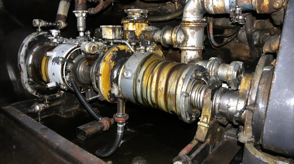
The turbo soak back pump 40182032 is an electric auxiliary pump that keeps engine oil circulating through the turbocharger bearing cavity after shutdown and before startup—two critical windows when the main lube pump isn’t running.

After shutdown, residual heat migrates from the turbine into the bearing housing, a phenomenon called heat soakback. Without active oil flow, that heat cooks residual oil into carbonaceous deposits that degrade bearing surfaces. The pump runs for roughly 30–35 minutes post-shutdown, continuously removing that heat and preventing coke formation.

Before startup, the pump handles turbo prelubrication by circulating filtered oil through the bearings for several minutes before fuel injection begins. It keeps running until main lube pressure reaches approximately 20 PSI, at which point a pressure-operated check valve blocks soak-back flow and the main system takes over. Oil supply pressure during pump operation stays within a nominal 10–35 PSI range.

The First Signs Your 40182032 Is Starting to Fail

When your 40182032 begins to fail, you’ll likely notice reduced turbocharger spool-up first—the turbo takes longer to reach operating speed because oil pressure delivered during pre-lube or post-shutdown cycles is insufficient to maintain proper bearing lubrication. You may also hear unusual whining or grinding noises from the pump assembly, signaling early bearing wear or rotor imbalance that will worsen without intervention. Fluctuating boost pressure follows as a direct consequence, since inconsistent lubrication degrades turbo bearing integrity and disrupts the stable rotor speeds needed to maintain steady airflow to the engine.

Reduced Turbo Spool-Up

Sluggish turbocharger response during acceleration is often the earliest indicator that your 40182032 soak back pump is beginning to fail. When the pump isn’t pre-lubricating bearings before fuel injection, you’ll notice pronounced turbo lag and compromised spool dynamics during initial RPM rise. Monitor your compressor bearing oil pressure closely—readings below 10 PSI during pre-lube cycles signal inadequate pump flow before the pressure stabilizes within the expected 10–35 PSI range. You should also track whether the pump energizes during its required 30–35 minute post-shutdown sequence. Skipped or intermittent cycles directly degrade subsequent spool-up performance. Listen for cavitation or unusual humming during pump operation, as these sounds indicate restricted suction or a failing drive mechanism that’ll worsen spool dynamics over time.

Unusual Whining Noises

Beyond sluggish spool-up, your 40182032 will often announce deeper mechanical trouble through sound before any pressure gauge confirms a problem. A rising high-pitched whine during shutdown or pre-lube cycles typically signals bearing fatigue or rotor imbalance developing inside the pump. If that whine intensifies proportionally with pump voltage, suspect motor winding degradation or voltage harmonics driving higher current draw toward the 12 A peak threshold.

A sudden shift from a soft whirr to harsh metallic noise within the 30–35 minute post-shutdown soak cycle frequently precedes total oil flow loss, often caused by suction-line cavitation. When the whining stops upon de-energizing the pump but returns immediately on restart, you’re likely dealing with an electrical fault in the motor or inverter drive rather than a transient oil condition.

Fluctuating Boost Pressure

Watch for these warning indicators:

  • Post-shutdown oil pressure dropping below 10 PSI on your 0–100 PSI gauge during the soak cycle
  • Erratic spikes above 35 PSI suggesting relief valve malfunction or internal blockage
  • Inconsistent pre-lube flow at the turbo inlet after pump energization
  • Air entrainment or foaming visible in the filter housing during operation
  • Repeated manual restarts required to re-prime the soak-back system

Each symptom compounds the next—address them before bearing failure forces a full turbocharger replacement.

What Strange Pump Noises Are Really Telling You

Strange noises from your soak back pump 40182032 often carry specific diagnostic information you shouldn’t ignore. A grinding or rumbling during the 30–35 minute post-shutdown run points directly to bearing wear or rotor rubbing—don’t let it continue operating under those conditions. Intermittent clicking on start or stop suggests failing motor brushes or a deteriorating AC motor rotor; check continuity and winding resistance immediately.

High-pitched whining that shifts with voltage typically signals cavitation from air ingestion caused by a restricted suction line. Verify your inlet tubing measures at least 5/8″ and remains fully unobstructed to sustain the required 10–35 PSI output. A sputtering sound during priming confirms air in the line—disconnect the outlet at the turbo filter head and run the pump until you see continuous oil flow.

A loud hum approaching the 12 A maximum at 74 VDC means shut it down and inspect the motor and bypass valves immediately.

Wiring and Sensor Failures That Kill the 40182032 Pump

electrical and sensor failures

Once you’ve ruled out mechanical noise sources in the 40182032, shift your attention to the electrical and sensor circuits that control it—because a perfectly functional pump motor still won’t run if its supply wiring, control signals, or feedback sensors are compromised.

Start sensor diagnostics and control wiring inspections by targeting these five critical failure points:

  • Zero current draw at pump leads — open DC supply wiring or blown fuses in the 40–90 VDC circuit
  • Voltage drop under load — corroded grounds or chafed harnesses causing the pump to stall despite nominal battery voltage
  • Abnormal winding resistance — failed motor windings reading open or shorted against factory specs
  • No automatic activation — burned relay contacts or faulty computer enable signals blocking post-shutdown sequencing
  • Forced inhibit faults — bad pressure/flow sensors or stuck check valves feeding false fault data to control logic

Measure methodically. Each failure point narrows your diagnosis.

Oil Starvation and Flow Problems in a Failing 40182032

Behind every 40182032 failure mode you’ve diagnosed so far—noise, wiring faults, sensor errors—oil starvation is the consequence that destroys turbocharger bearings if you don’t catch it fast.

When the pump’s running but compressor bearing oil passage pressure reads below 10 PSI, you’ve got either pump failure or inlet blockage restricting flow before it reaches critical lubrication points. Disconnect the outlet and watch for continuous, steady oil flow during priming—slow or intermittent delivery signals air cavitation from a restricted suction line or a leaking inlet fitting drawing air instead of oil.

Frothy, air-filled oil at the outlet confirms cavitation is collapsing your oil film across turbo bearings. Check the suction line for kinks, collapsed sections, or loose pickup connections immediately. Internal pump wear also drops outlet pressure below the 10–35 PSI operating threshold, so always verify pressure with a gauge before condemning external plumbing alone.

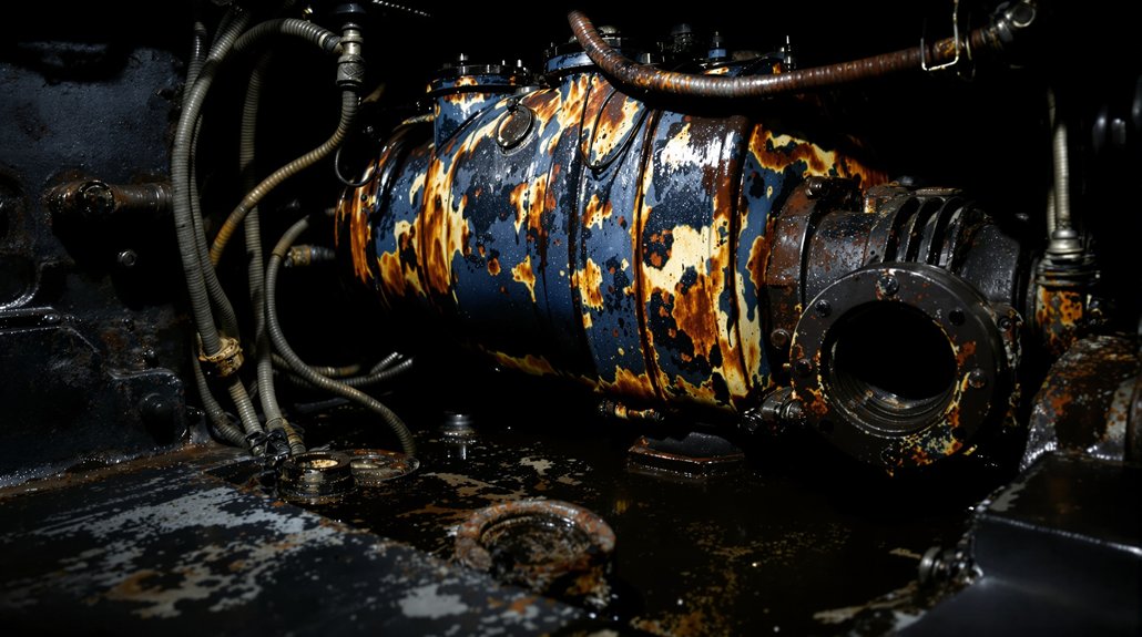
What 40182032 Pump Failure Does to Your Turbocharger After Shutdown

turbocharger heat soak coking

When the 40182032 fails and post-shutdown circulation stops, your turbocharger enters a heat-soak condition it can’t recover from on its own. Turbine temperatures near 1,000°F remain trapped in the bearing cavity while oil flow stops completely, triggering turbo bearing-coking that hardens residual lubricant into tar-like deposits.

Every failed cooldown cycle compounds the damage:

  • Coked oil clogs passages, starving bearings of the film thickness they need to survive
  • Blocked relief valves accelerate pressure loss during the next start cycle
  • Start-up wear intensifies as dry bearings absorb full rotor load at 100,000+ RPM
  • Shaft surfaces develop bluish-yellow heat tinting, signaling irreversible metallurgical damage
  • Scored bearing surfaces appear within hundreds of operating hours instead of full service intervals

You’re not just shortening turbo life — you’re forcing premature replacement or major overhaul on a timeline the manufacturer never intended.

How to Confirm the 40182032 Pump Is the Root Cause

Confirming the 40182032 as the root cause requires isolating it systematically before condemning the turbocharger or surrounding components. Start with electrical isolation: clamp a meter around the pump leads and verify it draws up to 12 A at 74 VDC during post-shutdown cycles. No current or markedly reduced draw points directly to motor failure or an open circuit.

Next, perform flow visualization by disconnecting the outlet at the turbocharger filter head with fuel disabled. Continuous, bubble-free oil flow confirms suction integrity; intermittent flow or air entrainment signals pump or suction-line leakage. Follow that with a pressure test—install a 0–100 PSI gauge at the compressor bearing oil passage and confirm 10–35 PSI while the pump runs engine-off. Pressures outside that range indicate pump or relief valve faults. Finally, bypass the filter and compare flow; restored output confirms a blockage rather than pump failure.

Replace or Repair Your Soak Back Pump 40182032?

diagnostics determine repair vs replacement

Once you’ve isolated the 40182032 as the root cause, your next decision is whether to replace or repair it—and that choice hinges on what the diagnostics actually revealed.

Before committing to either path, run your cost analysis against these findings:

  • No supply voltage or blown fuses? Repair wiring first—don’t replace prematurely.
  • Current approaching 12 A @74 VDC with abnormal noise? Replace immediately; bearing or winding failure isn’t field-repairable.
  • Output pressure below 10 PSI? Clear blocked lines and inspect the strainer before condemning the pump.
  • Pressure exceeding 35 PSI? Repair the relief valve assembly—the pump itself may be serviceable.
  • Seized rotor, corrosion, or failed insulation tests? Replace without hesitation; refurbishment isn’t viable.

Always review your warranty options before purchasing a replacement unit—valid coverage may eliminate out-of-pocket costs entirely. Let diagnostics drive the decision, not assumption.

Frequently Asked Questions

What Are the First Signs of Turbo Failure?

You’ll first notice boost lag during spool-up, signaling inadequate pre-lubrication from a failing soak-back pump. Listen for unusual whining or grinding—that’s shaft play from metal-to-metal contact caused by oil starvation. You’ll also detect excessive smoke, fluctuating boost pressure, and poor fuel efficiency. Post-shutdown overheating and coke deposits in the bearing cavity confirm the pump’s 30–35 minute cooling cycle has failed.

What Is the Most Common Reason for Turbo Failure?

The most common reason for turbo failure is oil coking in the bearing cavity. When you operate at high turbine temperatures exceeding 300°C, thermal degradation transforms lubricating oil into carbonaceous deposits that restrict flow and starve bearings. Oil contamination from fuel dilution, soot, or metallic particles accelerates this process. Foreign debris entering oil passages further blocks lubrication channels, causing metal-to-metal contact at rotor speeds exceeding 100,000 RPM, ultimately producing bearing seizure and catastrophic failure.

Can Low Oil Cause Turbo Failure?

Yes, low oil can cause turbo failure. Imagine this: you’re operating at full throttle when low pressure silently starves your bearings. Metal contacts metal. You’ll notice rising vibration, sudden power loss, then catastrophic seizure. Oil degradation accelerates this—thermally decomposed oil coats bearing surfaces with hardened deposits, restricting clearances. Even brief pressure drops below 10–20 PSI during start/stop transients trigger irreversible damage, demanding immediate turbocharger replacement.

How Do I Know if My Turbo Is Clogged?

You’ll know your turbo’s clogged by checking these indicators: reduced oil flow (below 10 PSI) during pre-lube, dark tar-like deposits signaling charger contamination on filter elements, and relief valve actuation from downstream turbine blockage. Disconnect the outlet line briefly while energizing the soak back pump—absent continuous flow confirms internal obstruction. Abnormally low bearing pressure (0–10 PSI) combined with elevated turbo temperatures solidifies the diagnosis.

What Parts Replace Worn Locomotive Valve Gear Systems?

What Parts Replace Worn Locomotive Valve Gear Systems?

You’ll need to replace several key components in locomotive valve gear systems when wear exceeds 0.015 inches during 90-day inspections. Vital parts include eccentric rods at pivot points, crossheads with guides, valve rods with packing, and linkages affecting timing. The Walschaerts system requires attention to expansion links, combination levers, and lifting links. Replace worn eccentric cranks when radial play surpasses 0.015 inches, and guarantee die block clearances stay under 0.030 inches. Precision-machined replacement parts using modern alloys and coatings offer enhanced durability. Understanding the complete maintenance protocol reveals additional vital wear points and specialized components.

What Parts Replace Worn Locomotive Valve Gear Systems?

Key Takeaways

  • Eccentric rods require precision-machined replacements at pivot points to maintain proper alignment and prevent system misalignment.
  • Worn crossheads and guides must be replaced with properly lubricated components to ensure smooth continuous motion.
  • Valve rods with deteriorated packing need replacement to prevent steam leaks and maintain effective sealing.
  • Expansion links and die blocks should be replaced when clearances exceed 0.030 inches to maintain proper valve timing.
  • Lifting links and combination levers require replacement with parts meeting exact specifications to ensure proper system functionality.

Common Valve Gear Wear Points

Four significant wear points in locomotive valve gear systems require consistent monitoring and maintenance. You’ll need to focus on eccentric rods, crossheads and guides, valve rods with their packing, and the system’s linkages and levers. Each component plays a critical role in maintaining precise valve timing and ideal steam distribution.

When inspecting for eccentric rod wear, you’ll find the most significant deterioration at the pivot points where rotational forces are highest. You must replace worn eccentric rods with precision-machined replacements to prevent misalignment issues that can stress connected components. Your valve rod maintenance protocol should include regular inspection of the packing to prevent steam leaks and guarantee proper sealing. Dust and debris in the mechanism can accelerate wear rates significantly.

Common Valve Gear Wear Points

The crossheads and guides demand particular attention due to their continuous reciprocating motion. You’ll need to maintain proper lubrication schedules and verify guide alignment to prevent accelerated wear. It’s necessary to precision-machine replacement crossheads to exact specifications for maintaining system accuracy.

Your inspection routine must include checking all linkages and levers for wear at their pivot points. These components control valve timing precision, and any deterioration will affect steam distribution efficiency. You’ll notice that worn linkages often manifest as inconsistent valve timing, requiring immediate replacement to maintain system performance. Remember that proper alignment of all replacement parts is imperative for preventing premature wear and guaranteeing ideal valve gear operation.

Essential Replacement Components

Maintenance technicians must prioritize three essential valve gear components when conducting replacements: the eccentric crank, expansion link, and combination lever. These components form the core of valve gear functionality and require precise assessment during maintenance operations. You’ll need to inspect the eccentric crank’s mounting points and connection to the eccentric rod, as wear in these areas directly impacts valve timing accuracy. The advent of the Baker Valve Gear eliminated many sliding parts, reducing wear concerns in some locomotives.

Essential Replacement Components

The expansion link’s pivot points and die blocks demand thorough examination, as they’re vital for maintaining proper cutoff points. When replacing these components, you’ll need to verify proper clearances and alignment to guarantee maximum steam distribution. The combination lever’s connections to both the union link and crosshead must maintain exact specifications to preserve valve timing integrity.

  • Inspect eccentric crank bearings for radial play exceeding 0.015 inches
  • Check expansion link die block clearances – should not exceed 0.030 inches
  • Verify combination lever pin holes for ovality within 0.005 inches
  • Test lifting link assemblies for freedom of movement without binding

Understanding replacement importance means recognizing how these components interact within the valve gear system. You’ll need to maintain proper tolerances during installation, confirming each replaced part meets manufacturer specifications. The lifting links and arms, while secondary to the main components, still require careful attention during reassembly. Remember to check all fastening points and confirm proper lubrication channels are clear before returning the locomotive to service.

Walschaerts System Maintenance Parts

walschaerts system repair components

You’ll find primary access points for the Walschaerts valve gear system at the expansion link housing and return crank assembly, which require regular inspection through dedicated maintenance ports. The most substantial wear typically occurs at the union link pivots and lifting arm joints, where metal-on-metal contact creates friction points requiring monthly lubrication. Critical measurements of these wear points must be taken during your 90-day maintenance intervals, with replacement necessary when clearances exceed 0.015 inches. The external mounting design of the Walschaerts system made it far superior to the between-wheel Stephenson gear for maintenance accessibility.

External Component Access Points

Several critical access points on the Walschaerts valve gear system enable proper maintenance and adjustment of external components. When performing lubrication techniques, you’ll need to access the expansion link bush, which serves as the primary point for applying lubricant and making precise adjustments to the expansion link assembly. The weigh shaft bracket provides direct access for inspection and oiling procedures of the weigh shaft mechanism. This external placement reflects the improved accessibility design that made Walschaert gear superior to earlier systems.

External Component Access Points

For adjustment procedures, you’ll find these essential access points:

  • Starlock washer location for securing the push rod connector
  • 2BA nut position for expansion link adjustments
  • Grub screw access for lifting arm lock-down
  • Weigh shaft bracket opening for maintenance operations

The grub screw access point requires particular attention during maintenance, as it’s imperative for locking the lifting arm in its correct position. When working with the 2BA nut access point, make certain you maintain proper torque specifications to secure the expansion link components effectively. The starlock washer access enables secure attachment of the push rod connector to the reversing lever arm, which is essential for proper valve timing and operation.

Common Wear Points Identified

Identification of wear points in the Walschaerts valve gear system requires systematic inspection of key components that experience constant mechanical stress. You’ll need to focus on three primary areas where worn components typically manifest: motion transmission assemblies, structural supports, and adjustment mechanisms. Steam engines with piston valve designs tend to show less wear on valve surfaces due to their ring support system.

Component GroupCommon Wear PointsMaintenance Strategy
Motion PartsRadius rods, valve spindlesMonthly inspection, lubrication
Support StructureWeigh shaft brackets, framesQuarterly alignment check
Adjustment PointsExpansion links, timing screwsBi-weekly calibration
Critical InterfacesBushes, piston valve ringsRegular replacement schedule

Your maintenance strategies should prioritize the inspection of lifting links and arms, which bear significant operational loads. When examining expansion link bushes, check for excessive clearance that could affect valve timing accuracy. Pay particular attention to eccentric rod wear patterns, as these directly impact steam distribution efficiency. Don’t overlook the weigh shaft components, as their deterioration can lead to improper valve events. Regular monitoring of crosshead wear ensures ideal motion transfer through the valve gear system.

Modern Manufacturing Solutions

While traditional manufacturing methods once dominated locomotive valve gear production, modern solutions have revolutionized the replacement parts industry through advanced materials and precision technologies. You’ll find that modern materials like ceramic coatings and high-performance alloys greatly extend component life spans, while manufacturing innovations such as 3D printing and precision CNC machining deliver parts with unprecedented accuracy. The evolution from simple tappet gear to modern systems demonstrates the industry’s continuous advancement in valve operation efficiency.

The integration of computer-aided design and advanced inspection techniques guarantees your replacement components meet exact specifications. When you’re upgrading worn valve gear systems, you’ll have access to these cutting-edge solutions:

  • Titanium and stainless steel valve rods with ceramic coatings that reduce friction by up to 60%
  • Advanced polymer eccentric straps featuring self-lubricating properties
  • Tungsten carbide die blocks manufactured using powder metallurgy techniques
  • Modular valve gear assemblies with quick-connect components for rapid maintenance
Modern Manufacturing Solutions

Your maintenance operations benefit from condition monitoring systems that utilize predictive analytics to forecast component wear. These systems interface with electronic control modules to optimize valve timing and reduce mechanical stress. Additive manufacturing now enables you to produce complex geometries previously impossible with traditional methods, while laser surface treatment enhances the durability of high-wear surfaces.

The implementation of lean manufacturing principles in the production process guarantees you receive high-quality replacement parts with minimal lead times. Quality control measures, including ultrasonic testing and X-ray tomography, verify that each component meets stringent performance standards before installation.

Historical Valve Gear Types

types of valve gear

You’ll find that Stephenson’s original design evolved from fixed eccentrics to adjustable lap configurations, establishing early standards for steam distribution timing. Walschaerts’ external mounting system offers you superior maintenance accessibility with reduced downtime for valve gear inspections and repairs. Baker’s pin-joint mechanisms eliminate the wear-prone sliding blocks found in other systems, resulting in extended service intervals and reduced maintenance requirements for your locomotive’s valve gear components. The Lentz valve system introduced in the early 1900s provided significant fuel savings for steam locomotives compared to traditional slide valves.

Early Stephenson Design Evolution

When Robert Stephenson and his team introduced their revolutionary valve gear system in 1842, it marked a significant advancement in steam locomotive technology. Their innovations addressed critical mechanical challenges through variable lead design and customizable drive configurations. You’ll find the system’s primary components – eccentric cams, rods, and sliding valves – working together to precisely control steam flow, though internal mounting often complicated maintenance procedures. Father of Railways George Stephenson’s early career experiences at Wylam Colliery directly influenced these mechanical innovations.

Early Stephenson Design Evolution

The early Stephenson design offered several notable features for steam locomotive operations:

  • Eccentric mounting inside the locomotive frames provided protected component placement
  • Reversing lever mechanism enabled precise control of valve timing and steam volume
  • Variable lead characteristics improved efficiency across different operating speeds
  • Multiple link options (locomotive and launch) allowed application-specific customization

When maintaining these systems, you’ll need to take into account the inherent accessibility issues. The internal placement requires partial locomotive disassembly for repairs, making lubrication and adjustment particularly challenging. Despite these maintenance hurdles, the Stephenson design’s mechanical sophistication established foundational principles that influenced subsequent valve gear developments, including the Gooch and Walschaerts systems.

Walschaerts External Mounting Benefits

The Walschaerts valve gear system addressed the maintenance challenges inherent in Stephenson’s internal mounting design through its revolutionary external configuration. Unlike its predecessor, you’ll find all critical components mounted outside the locomotive frames, providing unprecedented service accessibility and simplified maintenance procedures.

Walschaerts External Mounting Benefits

When replacing worn components, you’ll appreciate the mounting benefits of this external arrangement. The clear space between frames eliminates the need for complex internal access procedures, allowing direct visual inspection and efficient component replacement. Critical wear points on the expansion link, union link, and radius rod can be monitored without frame dismantling. The eccentric crank and rod require precise alignment for optimal valve control.

The system’s external mounting also facilitates precise adjustments to the center-pivoted swinging link and combination lever proportions. You’ll need to maintain proper alignment of the return crank and guarantee the radius rod’s pivoting block moves smoothly throughout the expansion link’s curve. Regular inspection of these external components prevents excessive wear and maintains ideal valve timing. When replacement becomes necessary, the external configuration allows you to swap components without disturbing the locomotive’s frame integrity, greatly reducing maintenance downtime.

Baker Pin Joint Advantages

Developed as a major advancement over Walschaerts gear, Baker’s pin joint mechanism revolutionized locomotive valve systems after 1910. When you’re replacing worn valve gear components, you’ll find Baker’s design offers significant maintenance advantages through its innovative J-shaped main link and bellcrank assembly. The pin joint configuration eliminates the sliding expansion link, substantially reducing wear points while maintaining precise valve travel adjustment capabilities. A.D. Baker Company first patented this innovative design in 1903.

Baker Pin Joint Advantages

Key Baker advantages for replacement components include:

  • Pin joints experience minimal die slip, extending service intervals
  • No sliding components means fewer wear-prone surfaces to maintain
  • Continuous valve travel variation without expansion link wear
  • Direct frame mounting simplifies alignment during rebuilds

You’ll notice the gear’s durability particularly in high-mileage applications, where the pin joint assembly outperforms traditional sliding mechanisms. When servicing eastern railroad locomotives, especially N&W, C&O, and Nickel Plate Road units, you’ll commonly encounter Baker installations. The system’s robust design, produced by Pilliod Co., guarantees consistent valve timing even under heavy use. For maintenance crews, the reduction in wear-related adjustments and simplified pin joint servicing translate to improved reliability and reduced downtime.

Maintenance Scheduling and Inspections

Regular maintenance and inspection protocols for locomotive valve gear systems encompass four essential tiers of examination: daily, weekly, monthly, and annual assessments. You’ll need to implement strict inspection frequency guidelines, starting with daily checks of fluid levels, critical components, and safety compliance measures. Your maintenance protocols must include thorough examinations of handrails, stairways, and structural integrity points.

When conducting monthly inspections, you’ll spend approximately two hours cleaning the motor assembly and four hours controlling motor pumping functions during quarterly checks. Establishing preventive maintenance schedules significantly improves locomotive longevity and reliability. The maintenance schedule intensifies with semi-annual propulsion equipment inspections requiring six hours, while annual protective equipment assessments demand eight hours of detailed examination.

Maintenance Scheduling and Inspections

Your specialized component inspections must focus on boiler elements, including riveted seams, flanged sheets, and staybolts. You’ll need to verify valve seats and guides for wear patterns, verifying proper alignment before installing replacement valve springs. The dry pipe requires particular attention to identify erosion and crack formation.

Long-term maintenance planning should incorporate emission control system upgrades and advanced diagnostic tool implementation. You’ll conduct biennial complete defect inspections, allocating 12 hours for thorough system evaluation. Critical areas include checking threaded attachment studs for corrosion and examining the throttle handle mechanism’s operational integrity. This systematic approach guarantees ideal valve gear system performance and extends component longevity through preventive maintenance.

Custom Fabrication Techniques

bespoke manufacturing methods applied

Building upon established maintenance protocols, custom fabrication techniques now stand at the forefront of locomotive valve gear system restoration. You’ll find that precision engineering through CAD-based design and CNC machining enables the creation of exact-fit replacement components for worn valve gear assemblies. These advanced manufacturing processes guarantee dimensional accuracy while maintaining the strict tolerances required for ideal valve timing and operation. The robust design principles of Walschaerts valve gear make it particularly suitable for custom part fabrication and restoration.

When you’re dealing with heritage equipment repairs, custom fabrication offers several critical advantages through specialized services. Modern technology, combined with traditional craftsmanship, allows you to reproduce vintage parts that aren’t commercially available. The process typically involves material selection, prototype development, and rigorous quality control measures to verify specifications.

Custom Fabrication Techniques

Here’s what you’ll need to take into account for successful custom fabrication:

  • Material selection requirements: high-grade stainless steel or carbon steel with specific tensile strength ratings
  • CAD-driven precision measurements accurate to within 0.001 inches
  • CNC machining parameters calibrated for complex geometric profiles
  • Quality control protocols including stress testing and dimensional verification

The implementation of simulation studies before production helps validate the kinematics of your custom-fabricated components. You’ll want to focus on sheet metal fabrication techniques when dealing with valve covers and protective housings. Through rapid turnaround manufacturing processes, you can expect completed parts within 2-3 weeks, depending on complexity. This approach not only guarantees cost-effective solutions but also assures the durability and reliability necessary for sustained locomotive operation.

System Performance Monitoring

While maintaining ideal valve gear performance requires constant vigilance, modern monitoring systems now provide extensive real-time data analysis capabilities. You’ll find sophisticated monitoring technologies like Lat-Lon’s LMU and MotivePower’s Central Diagnostics System delivering thorough performance metrics directly to your mobile devices or web dashboards. EMD’s Intellitrain monitoring system generates custom alerts and reports from daily fault history tracking.

To maximize system efficiency, you’ll want to utilize electronic steam engine indicators that measure valve settings with high precision. These tools install in under an hour and provide critical data about mechanical and thermodynamic processes within your locomotive’s cylinders. You’re able to detect issues like poor running characteristics or increased consumption before they become major problems.

System Performance Monitoring

When monitoring valve gear performance, you’ll need to track multiple parameters simultaneously. The LMU system offers four analog and 12 digital inputs for customized monitoring, while MotivePower’s solution tracks everything from throttle positions to hard couplings. You can install digital wiring harnesses in less than three hours to streamline your monitoring setup.

Your performance analysis should include real-time data capture and storage capabilities. Modern systems calculate indicated work and horsepower for each cylinder, allowing you to quickly evaluate steam distribution quality after brief test runs. Through graphical interfaces, you’ll easily interpret data trends and make informed adjustment decisions. By implementing these monitoring technologies, you’re able to reduce maintenance costs, improve asset usage, and guarantee your valve gear systems operate at peak efficiency.

You may also like to read – The Ultimate High-Performance Valve Train Upgrades: Enhance Your Engine.

Frequently Asked Questions

How Long Does a Typical Valve Gear Replacement Process Take to Complete?

You’ll typically spend 3-5 days completing a valve gear replacement timeline, depending on system complexity and part availability. Your maintenance schedule must account for 8-12 hours of disassembly, 4-6 hours of inspection and cleaning, 10-14 hours for reassembly, and 6-8 hours for testing and adjustments. Critical valve gear maintenance factors include technician expertise, workspace conditions, and equipment accessibility.

What Specialized Tools Are Required for Valve Gear System Repairs?

You’ll need specialized wrenches calibrated for precise torque settings and alignment tools designed specifically for valve gear components. Essential equipment includes a valve spring compressor for safe spring manipulation, magnetic pickup tools for retrieving fallen parts, and air fittings for maintaining valve position. Don’t forget your locomotive inspector’s hammer and valve gear calculator for accurate measurements and proper timing adjustments.

Can Original Manufacturer Specifications Be Modified for Improved Performance?

Like a skilled chef tweaking a classic recipe, you can modify original manufacturer specifications for performance enhancements. You’ll find success by adjusting valve timing +/- 0.015″, increasing valve lift by 15-20%, and optimizing lead clearances to 0.125″. While manufacturer modifications require precise calculations, you can achieve 8-12% efficiency gains through strategic adjustments to valve overlap, duration, and steam admission timing.

What Are the Cost Differences Between Various Valve Gear Replacement Options?

You’ll find significant cost variations across valve gear replacement options. Walschaerts systems typically run 30-40% higher due to complex machining requirements and specialized components. Your Stephenson gear presents mid-range costs, varying by configuration. Gooch designs offer the most economical solution, often 25% less than Walschaerts. Your cost analysis should factor in material grades, machining precision, and labor expertise for each system.

How Does Climate Affect the Wear Rate of Valve Gear Components?

Picture a steel valve gear enduring nature’s relentless assault – you’ll find climate impact accelerates wear through multiple factors. You’re facing increased corrosion rates in humid conditions above 65% RH, while temperature swings of 40°F or more cause thermal stress on moving components. You’ll need to adjust your maintenance intervals: inspect linkages every 500 hours in coastal areas, and apply corrosion-resistant lubricants quarterly in high-moisture environments.

Translate »