
Unexpected brake faults, inconsistent response times, and repeat WABCO 26L failures are more than frustrating. They stop locomotives, disrupt schedules, and inflate maintenance costs. Technicians often replace parts without fixing root causes. Wiring checks look fine, yet faults return under load. Shops need clear guidance on how electrical, pneumatic, and firmware issues interact.
- Random brake application or release during operation
- Fault codes that disappear in the workshop but return in service
- Over‑sensitive or under‑responsive dynamic braking transitions
- Repeated valve or module replacement with no lasting improvement
- Difficulty reproducing failures on test stands
- Confusion between wiring faults, sensor faults, and ECU faults
- Inconsistent brake feel between locomotives in the same fleet
- Limited OEM documentation for mixed‑generation 26L + EBS setups
- Pressure tests passing, but performance still feels unsafe
- Lack of integration know‑how during post‑repair commissioning
| Pain Point | Likely Root Cause Area | Quick Check | Risk if Ignored |
|---|---|---|---|
| Intermittent brake faults in service | Electrical integrity | Measure loaded voltage at WABCO modules | Sudden loss or surge in braking |
| Different brake feel between locomotives | Calibration / firmware | Compare config files and event logs | Uneven train handling |
| Frequent valve or module replacement | Wiring / grounding issues | Inspect harness routing and shield term. | Rising spares and labor cost |
| Faults vanish in workshop | Vibration and temperature | Log data during on‑track testing | Hard‑to‑trace intermittent issues |
| Pressure correct, behavior wrong | Signal–pressure mismatch | Correlate sensor data with brake curves | Unsafe stopping distances |
| New parts, same old errors | Missed post‑repair steps | Review commissioning and test protocol | Repeat failures after release |
| CAN errors on mixed fleets | Firmware generation mismatch | Verify part numbers and software levels | Network instability, false trips |
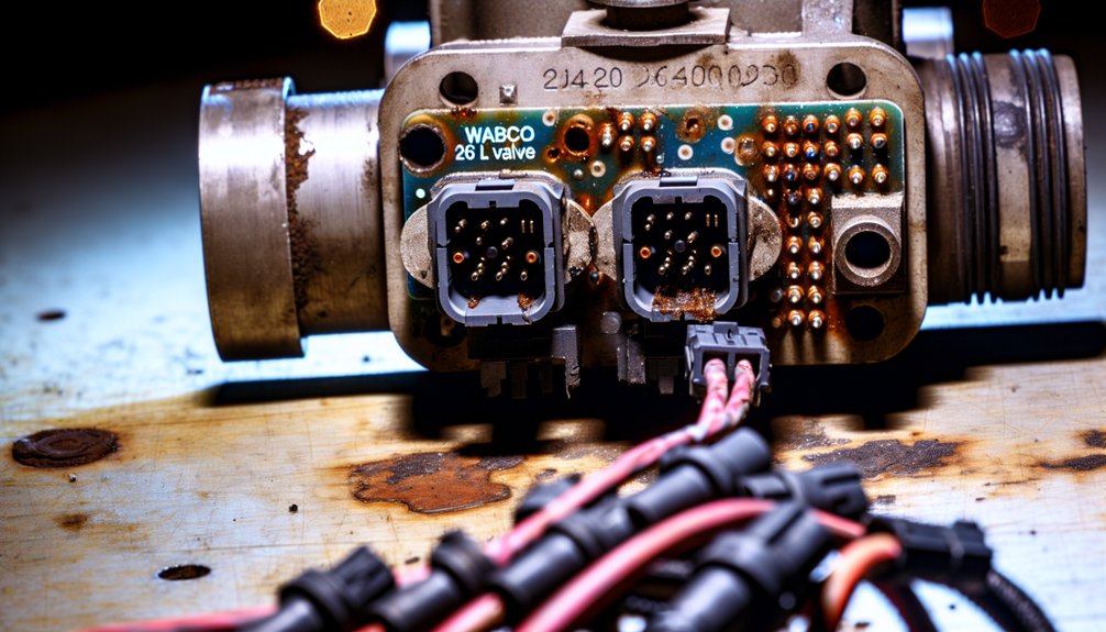
The WABCO 26L persists as an integration problem on locomotives. It forces electrical signal integrity, pneumatic brake pressure, and CAN‑based firmware logic to coexist in one tightly coupled system.
A compromise in any single domain destabilizes the others on the locomotive. Voltage drops trigger false fault codes. EBS generation mismatches corrupt calibration maps. Skipped post‑repair procedures conceal emerging failures. Harsh locomotive environments accelerate every failure driver simultaneously. Understanding each layer separately is where real diagnostic clarity begins.
Mikura International supports locomotive operators by supplying genuine WABCO brake components and related parts. This helps maintenance teams focus on correct integration instead of questioning part authenticity.
Key Takeaways
- Dual-domain coupling between electrical and pneumatic systems means degradation in one domain directly destabilizes the other, compounding integration failures.
- Poor grounding disrupts EBS ECU communication and generates misleading fault codes that incorrectly implicate modulators, valves, or sensors.
- Post-repair calibration is frequently skipped or performed incorrectly, leaving sensor errors and axle misconfigurations undetected until failure occurs.
- Silent firmware mismatches and network disturbances degrade brake performance before fault codes appear, delaying accurate diagnosis.
- Generic diagnostic tools miss real-time signal distortion and intermittent faults, preventing technicians from identifying true root causes.
What Makes WABCO 26L Assembly Integration So Persistently Problematic?

The WABCO 26L assembly creates persistent issues because of its dual-domain design reality.
It must manage electrical signal integrity and pneumatic brake pressure in one coupled unit.
When one domain degrades, the other loses stability and performance.
On locomotives, this becomes more complex due to long cable runs and harsh vibration.
Marine engines add moisture, corrosion, and hull-borne vibration to the same problem set.
Multiple factors drive recurring faults.
Sensor calibration errors create pressure deviations in critical braking cycles.
Network disturbances disrupt electronic brake control command delivery along the locomotive or vessel.
Poor grounding or incorrect wiring causes intermittent failures that defy quick diagnosis.
Older locomotive or marine electrical infrastructure may not fully match the 26L communication needs.
Fault logging occurs when sensor inputs become inconsistent, potentially reducing braking performance as a protective measure.
Calibration demands increase the integration challenge.
Post-repair calibration is mandatory but often skipped or performed incorrectly.
Tone ring misalignment leads to unstable wheel speed feedback on locomotives.
Wrong axle configuration parameters corrupt braking logic and system protection limits.
Missed low-speed brake tests after installation hide emerging fault conditions.
You are not dealing with a single, isolated device.
You are managing linked mechanical, pneumatic, and electronic dependencies in real time.
In locomotive and marine environments, these dependencies become tightly coupled and unforgiving.
Why Mixing EBS Generations Destroys 26L Firmware Compatibility
Persistent integration failures are not only caused by miscalibrated sensors or poor grounding.
They also appear when different EBS generations are mixed within the same 26L locomotive system.
Generation mismatch disrupts protocol integrity at several layers of the control architecture.
This makes firmware compatibility extremely difficult to sustain over the life of the locomotive.
Here is what happens when incompatible EBS generations are introduced in a locomotive brake system:
1. CAN communication collapses —
EBS 3 expects high‑speed J1939 data formats used in many modern locomotives.
Older modules transmit frames the EBS 3 ECU interprets as malformed messages, causing repeated timeouts.
2. Signal formats conflict —
EBS 2 actuators may output analog or different PWM profiles to control locomotive brake valves.
The EBS 3 controller flags these as invalid, triggering fault codes such as SPN 521 and ABS 10.
3. Calibration maps misalign —
EBS 3 firmware applies pressure curves tuned for its own generation of locomotive brake hardware.
When connected to EBS 2 valves, the pressure response deviates, producing recurring EBS 434 faults.
4. Configuration sequence fails —
During startup, the ECU reads part numbers from all connected EBS modules on the locomotive.
Unexpected or mixed‑generation identifiers cause the configuration routine to abort.
The ECU then disables correct brake recognition, modulation, and equalization across locomotive axles.
When the configuration routine processes mixed identifiers across stages, rounding errors accumulate, degrading the precision of each subsequent brake parameter calculation the ECU performs.
Each failure amplifies the next.
The result is a degraded locomotive brake system that becomes hard to trust and harder to diagnose.
How Connector Fit Fools Technicians Into Wrong 26L Sensor Pairings?
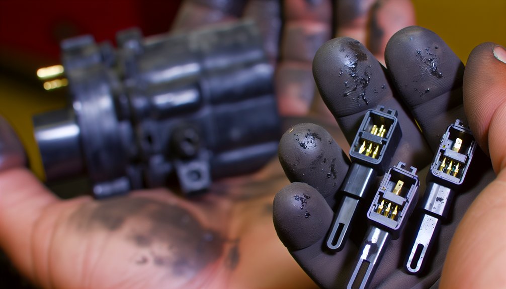
When a replacement 26L sensor’s connector mates cleanly with the harness plug, you’re likely to assume electrical compatibility—but physical fit doesn’t confirm signal protocol alignment, voltage tolerance, or CAN message structure. You can install a cross-generation sensor that powers up, passes a basic circuit check, and even streams plausible live data while the underlying pin assignments route signals incorrectly. Swapping sensors across EBS generations without verifying part number metadata exposes the system to silent firmware mismatches that degrade brake performance before a single fault code appears. Cross-referencing against the WABCO 480 series catalog numbers confirms whether overlapping part numbers within the same module family actually share compatible signal architecture.
Physical Fit Versus Electronic Compatibility
One of the most deceptive traps in WABCO 26L service work is the J2030 6‑pin Deutsch connector.
It fits identically across EBS 3, EBS 4, and EBS 5 sensor generations.
Locomotive and marine technicians often assume identical connectors mean full compatibility.
That assumption is dangerous on propulsion and braking systems.
There are no connector keying differences across these sensor generations.
So physical fit guarantees nothing electronically.
Here is what actually happens when you install the wrong sensor.
- The mismatched sensor transmits unreadable data to the ECU.
- Signal protocols differ across generations in locomotive and marine applications.
- The ECU rejects the sensor’s digital signatures during the software handshake.
- This rejection triggers calibration faults on the control system.
- The system can enter failure mode and restrict advanced EBS functions.
- You may see fault codes such as SPN 521 in diagnostic logs.
- These codes can lead to repeated, incorrect component replacements.
You cannot verify compatibility by visual inspection.
You must cross‑reference the full 12‑digit WABCO part number.
Then confirm that the communication protocol matches the ECU generation.
Always verify this before installation on any locomotive or marine engine system. An unprogrammed or misconfigured module can trigger false error codes that further obscure the root cause of sensor incompatibility during post-installation diagnostics.
Cross-Generation Sensor Swapping Risks
Cross-generation sensor swapping in WABCO 26L assemblies does not always show an error.
The sensors may appear correct and fit perfectly in place.
Bench tests can pass when connectors seat cleanly and resistance values look normal.
The real problem appears later during live operation.
The issue is not mechanical.
The failure happens at the protocol and signal level.
Different EBS generations use different signal characteristics.
EBS 3, EBS 4, and EBS 5 sensors can share identical housings.
However, they can transmit incompatible signals to the control unit.
In a locomotive braking system, this causes serious risk.
The control unit detects signal integrity violations during operation.
It logs implausibility fault codes, such as SPN 521.
The system may then shift into a degraded braking mode.
Initial self-checks may pass when the locomotive is stationary.
They can then fail under dynamic braking conditions.
You cannot use connector fit as a compatibility check.
Always confirm the full part number suffix before installation.
Match the sensor exactly with the correct EBS generation.
This practice helps maintain safe and reliable locomotive braking performance.
Passive WABCO ABS sensors should measure within the expected 1,000–1,300 ohm resistance range as a baseline electrical verification step.
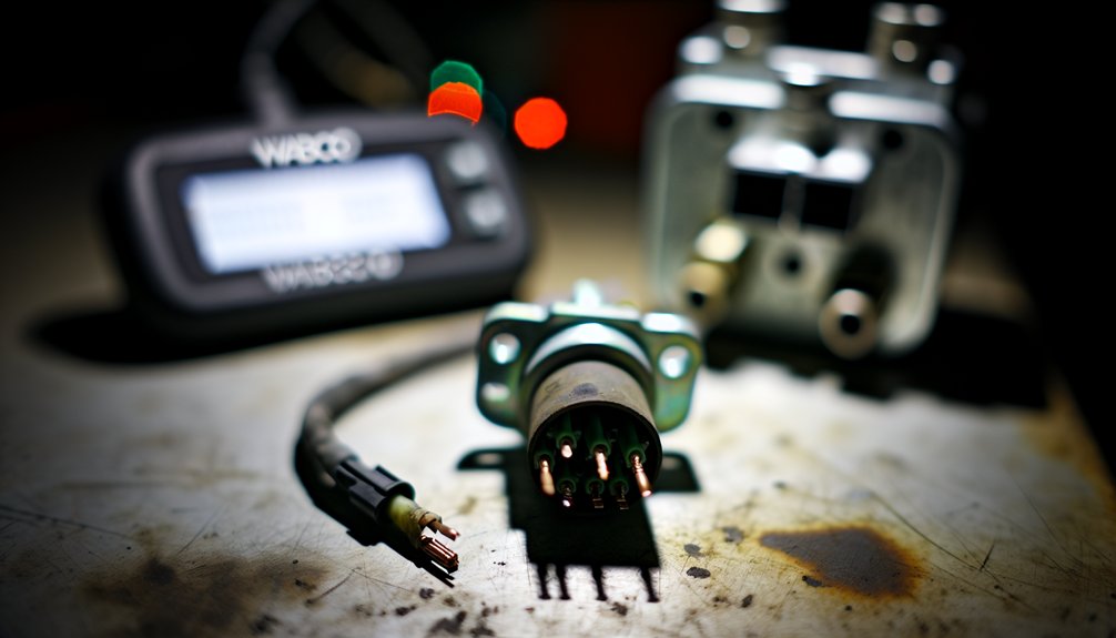
Calibration Steps Most Teams Skip After 26L Brake Service

After completing 26L brake service, you must verify axle configuration settings in your diagnostic software to guarantee the module reflects the correct brake system architecture—mismatched parameters cause false alerts and compromise DOT compliance. You’ll then need to run a full EBS parameter check using TOOLBOX version 12 or higher with a J1939-compliant adapter to confirm every sensor type and load-based braking preference aligns with the vehicle’s programmed specifications.
Finally, you can’t skip post-service low-speed testing, which validates that SAS calibration and ESC initialization were performed in the correct sequential order before returning the vehicle to service. The E8 ESC End of Line procedure is also required after steering repair or replacement and must be completed following any front wheel alignment.
Axle Configuration Settings Verification
When servicing the WABCO 26L brake system on a locomotive, axle configuration settings are often skipped.
Skipping this calibration step can create serious operational problems.
Incorrect axle configuration corrupts wheel assignment logic within the braking network.
It also invalidates sensor diagnostics across the entire brake control system.
Use WABCO TOOLBOX (v12+) with an RP1210C-compliant adapter for configuration checks.
Confirm the electronic configuration matches the locomotive’s physical brake architecture.
Verify these four parameters carefully:
- Axle configuration selection (for example 4S/4M or 6S/6M) matches the installed locomotive hardware.
- Sensor type, whether active or passive, and tooth wheel data are entered exactly as specified.
- Wheel diameter, equivalent tire size settings, and axle load ratings match actual locomotive specifications.
- Voltage supply to the ECU remains within 9.0–16.0 volts under normal operating conditions.
Finish by running a complete fault code scan.
Confirm there are no active faults before returning the locomotive to service with Mikura International support. Intermittent faults can be difficult to locate and repair, making thorough fault code review essential before clearing the system for operation.
Post-Service Low-Speed Testing
Many teams skip it, but that creates real safety risks.
Skipping calibration can hide sensor faults on locomotive brake systems.
It can also cause system initialization failures in critical control modules.
Always verify sensor contact at the tone ring.
Confirm at least 0.2 volts AC output at 30 RPM wheel rotation.
Inspect for test-stand induced faults before moving forward.
Workshop dynamometers can create misleading fault codes on locomotive systems.
These false codes can corrupt brake calibration results if left unchecked.
Check all sensor cables for 900–2000 ohms resistance.
Confirm vehicle supply voltage stays between 9.0 and 16.0 volts.
Voltage fluctuation can trigger false ABS-related fault indications in locomotives.
Clear all active fault codes outside allowable SAS or ESC parameters.
Do this before starting the brake calibration sequence.
If these steps are skipped, SPN 520210 FMI 14 may remain active.
That condition blocks proper ESC initialization on the locomotive.
Full EBS Parameter Check
Completing a full EBS parameter check after 26L brake service is never optional.
It is the step many maintenance teams skip.
This is where calibration failures usually begin in locomotive and marine brake systems.
After service, you must verify every parameter before the unit returns to operation.
Do not move the locomotive or sail the vessel before this verification.
Perform these four checks immediately after 26L installation:
- Confirm the ABS ECU receives stable 9.0–16.0 volts at all connectors.
- Complete sensor calibration. Verify wheel speed sensors read 900–2000 ohms. Confirm brake pressure sensor continuity holds.
- Perform axle verification. Confirm correct axle configuration and brake type settings. Match tone wheel configuration across all axles.
- Clear fault codes SPN 1807 FMI 08 and SPN 520210 FMI 14 after successful calibration.
Record the software version and EBS generation in your maintenance log.
Document all replaced sensor 12‑digit part numbers for traceability.
A single mismatched wheel speed sensor can degrade ABS responsiveness by 17% in wet conditions.
Ensure all records are complete before Mikura International releases the locomotive or marine engine back to service.
Voltage Drops and Ground Faults Behind False 26L EBS Codes
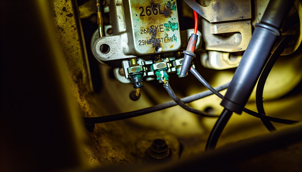
Electrical faults in 26L EBS systems often arise from voltage drops and ground path failures. Components get blamed, but they are often fine.
In locomotives and marine engines, check grounding topology first. Poor grounding disrupts stable communication with the EBS ECU.
Corrosion between the main frame and bogies or mounting points increases resistance. This resistance interrupts reference signals and power return paths.
Any reading above 0.3 ohms between cab and frame needs attention. Values above this threshold indicate compromised grounding.
Voltage grading across power and control connectors is equally important. High current draw during dynamic braking causes voltage drops.
These drops can generate fault codes that resemble modulator or valve failures. The EBS system only reports symptoms.
Corroded pins with light green oxidation increase resistance over time. Both power and ground circuits degrade progressively.
On locomotives and marine engines, J1939 CAN bus errors can compound these issues. Ground loop interference corrupts sensor and actuator data.
Faulty terminating resistor symptoms may appear when ground circuits are unstable. The bus then shows intermittent or drifting values.
Do not rely only on the fault codes from the EBS controller. They usually flag “voltage low” without revealing the real cause.
Use a digital multimeter to measure resistance in the ground paths. Test both with the system idle and under electrical load. Basic diagnostics can be performed without a PIN, reserving PIN access only for security-relevant functions within the diagnostic software.
Confirm clean, low-resistance bonds between cab, frame, engine block, and control cabinets. Correct these before replacing any EBS component.
How Fault Code Symptoms Obscure the Real 26L Electrical Cause
Fault codes in the WABCO 26L EBS system can mislead marine and locomotive diagnostics.
They do not always indicate the real electrical failure.
Sensor masking is a core problem in these environments.
Sensor masking distorts signals in marine and locomotive environments, causing ECUs to misread mechanical issues as electrical faults.
Contamination or misalignment distorts sensor signals during marine or locomotive operation.
The ECU often misreads these as electronic faults instead of mechanical issues.
Waveform aliasing adds another blind spot.
Generic diagnostic tools miss real-time signal distortion under dynamic braking.
Intermittent faults vanish before technicians can capture accurate data.
Four patterns routinely hide the true electrical cause:
1. Outdated firmware flags valid sensor outputs as fault conditions.
This pushes diagnostics toward the wrong assemblies.
2. Oxidized ground terminals shift the baseline of sensor signals.
The system then mimics a sensor circuit failure on the locomotive or vessel.
3. Connector corrosion creates unstable electrical paths in harsh marine or rail environments.
These instabilities resemble ECU communication faults in the 26L system.
4. Intermittent fault histories may remain stored but unseen.
Many tools show only active codes, not historical patterns.
Stored DTCs are only cleared by deliberately clicking the Clear DTCs button, not by simply viewing or cycling power.
Each misleading symptom encourages unnecessary component replacement.
This wastes time and parts on marine engines and locomotives.
It also reduces reliability for operators who depend on accurate 26L diagnostics.
How Air Leaks Inside the 26L Modulator Valve Cause Pressure Faults

Internal air leaks inside the 26L modulator valve often trigger pressure faults in locomotive brake systems.
These faults may appear as electrical issues in diagnostic logs.
However, the root cause is frequently pneumatic, inside the valve body itself.
Internal leakage past the valve seat causes continuous exhaust during brake application.
You can confirm this by observing the exhaust port on a running locomotive.
Air will exit the exhaust port only when you apply the brake valve.
Isolating downstream brake cylinders or brake rigging will not stop this exhaust.
This proves the leak is inside the modulator valve, not in the brake cylinders.
Equalizing leaks make troubleshooting even more difficult on locomotives.
Damaged O‑rings at gauge ports or mounting plates cause a steady pressure bleed.
This prevents the equalizing reservoir from holding a stable reduction.
The result is erratic brake pipe control and recurring pressure fault indications.
| Leak Type | Trigger Condition | Indicated Repair |
|---|---|---|
| Valve seat leakage | During brake application | Replace modulator valve |
| Exhaust port leak | With brake pedal depressed | Treat as internal valve leak |
| Equalizing reservoir leak | Continuous pressure loss | Replace O‑rings and fittings |
Use soap solution or an approved smoke test on the locomotive brake stand.
Keep the brake stand cut in to locate active leaks under operating pressure.
When a modulator valve leaks continuously during service brake application, some technicians recommend replacing it with a non-ABS valve as an interim measure while sourcing OEM components.
Fix the Root Cause, Not Just the 26L Fault Code

A 26L fault code shows where to investigate, not what to replace.
Changing the modulator on a locomotive or marine engine without diagnostics wastes resources.
Replacing the 26L modulator without proper diagnostics wastes time, money, and resources better spent finding the real problem.
The fault will return if the root cause remains.
Complete these four checks before condemning the 26L assembly:
- Test control wiring and harnesses for ground faults, CAN bus errors, and voltage drop.
- Verify air supply quality by inspecting dryers, filters, and separators for moisture and oil contamination.
- Confirm sensor accuracy by checking pressure and load sensors that feed data to the brake control system.
- Inspect related brake components such as relay and quick-release valves for fault signatures similar to 26L.
Systematic diagnostics prevent cascade failures in locomotive and marine braking systems.
Fix the component that is truly defective. Aging leveling valves develop internal leaks that cause slow height drift, which can mask the true source of a recurring fault and lead to repeated misdiagnosis.
Frequently Asked Questions
Can Tone Ring Damage Trigger Recurring 26L Wheel Speed Sensor Faults?
Yes, tone ring wear can definitely trigger recurring 26L wheel speed sensor faults.
Cracks, missing teeth, or corrosion cause irregular magnetic pulse signals.
The locomotive control system reads these irregularities as sensor failure.
Recurring fault codes may appear even after replacing the wheel speed sensor.
This happens when the damaged tone ring keeps distorting the sensor signal.
Always inspect the tone ring condition during locomotive wheel speed sensor diagnostics.
Correct tone ring defects before deciding to replace the sensor again.
How Does ISO 7638 Socket Condition Affect 26L CAN Communication Reliability?
The ISO 7638 socket condition directly affects 26L CAN communication reliability.
Corroded CAN_H and CAN_L pins increase contact resistance.
Higher resistance attenuates signal levels and pushes them outside specification.
Locomotive control units then detect intermittent errors on the CAN bus.
You may see false communication fault codes and repeated retransmissions.
Prolonged degradation can even drive modules into bus‑off states.
Inspect socket pins on your locomotive at regular maintenance intervals.
Measure total CAN bus termination resistance from the ISO 7638 interface.
Clean oxidized pins carefully and replace severely pitted terminals.
Use approved dielectric grease to reduce moisture ingress at the connector.
This slows pin degradation and stabilizes your locomotive CAN network.
Does Suspension Modification After 26L Installation Require Full EBS Recalibration?
Yes. Suspension changes after 26L installation need full EBS suspension recalibration on locomotives or marine engines.
Update axle load parameters, ride height values, and brake force distribution settings in the ECU.
Without recalibration, the changed suspension geometry sends incorrect data to the control unit.
This can trigger fault codes, including WABCO EBS 434, on locomotive or marine braking systems.
Check and adjust sensor alignment on all height and pressure sensors after suspension work.
This helps avoid implausible signal errors and prevents uneven braking response in locomotive or marine applications.
What Sealing Methods Prevent Leakage During 26L Prototype Valve Testing?
Seal failure during 26L prototype valve testing can compromise entire locomotive brake assemblies.
Prevent leakage with precise O-ring selection matched to the brake system’s pressure and temperature range.
Ensure elastomer compatibility with the locomotive’s air supply quality and any condensate or oil carryover.
Apply potting compound carefully around electrical interfaces on control valves and sensor housings.
This blocks moisture ingress in harsh locomotive operating environments.
Verify the correct tightening torque on all valve fasteners using calibrated tools.
Inspect all sealing and seating surfaces for dust, rust, or machining debris before assembly.
Stabilize the test pressure for 30–60 seconds during 26L valve bench tests.
Record results against defined acceptance criteria used by Mikura International for locomotive applications.
How Does Road Impact Gradually Degrade 26L Wiring Harness and Sensor Integrity?
Road impact gradually degrades the 26L wiring harness in locomotives and marine engines.
Cumulative abrasion fatigue from repeated flexing fractures wire strands at termination points.
Insulation chafing against sharp mounting or chassis edges accelerates conductor exposure.
Vibration loosens connectors over time and weakens the pin-to-socket interface seal.
This loosening increases electrical resistance and causes intermittent 26L control faults.
Moisture then enters through compromised connectors and damaged seals.
Corroded terminals distort voltage and current signals from critical control circuits.
These distortions can generate false sensor readings and nuisance fault indications.
Floating rust particles and debris can also bridge contacts and short adjacent pins.
Physical debris impact can crack sensor housings mounted near running gear.
Cracked bodies allow water and contaminants into the sensing element area.
This contamination alters sensor air gaps and magnetic field strength.
Changed clearances disturb the tone ring signal and pulse train accuracy.
Progressive damage can eventually lead to loss of 26L control reliability.