
Locomotive technicians often waste hours chasing EPIC brake faults without a clear starting point. Random part replacement increases downtime and cost. A structured diagnostic path reduces guesswork. It protects expensive WABCO components and improves fleet reliability. With the right sequence, you fix faults faster and avoid repeat failures.
- Always pull J1587 codes before touching components
- Separate electrical, pneumatic, and mechanical symptoms early
- Verify sensor gaps before suspecting the EPIC ECU
- Check wiring integrity before replacing valves
- Confirm air supply quality and dryer performance
- Inspect for heat damage around brake cabinets
- Test battery and alternator output under load
- Record baseline pressures at key test ports
- Use only genuine WABCO locomotive brake parts
- Document each step for repeatable fleet procedures
| Pain Point | Immediate Action | Why It Helps |
|---|---|---|
| Unsure where to start troubleshooting | Download active and stored J1587 codes | Narrows faults before physical inspection |
| Repeated EPIC brake failures | Standardize a step‑by‑step diagnostic checklist | Removes guesswork and random part swapping |
| Inconsistent brake response | Verify wheel speed sensor gaps on all axles | Restores accurate slip and speed control |
| Frequent component burnouts | Inspect harness routing and heat shielding | Prevents recurring heat‑related failures |
| Unstable brake performance | Check voltage stability at EPIC ECU power pins | Avoids logic errors from low or spiking VDC |
| Air pressure drops under load | Leak‑test circuits and diaphragms with gauges | Pinpoints hidden pneumatic losses |
| Water or oil in brake air | Inspect filters, dryers, and compressor output | Protects valves and EPIC pneumatic modules |
| Confusion over parts quality | Use genuine WABCO parts from Mikura International | Ensures compatibility and long‑term reliability |
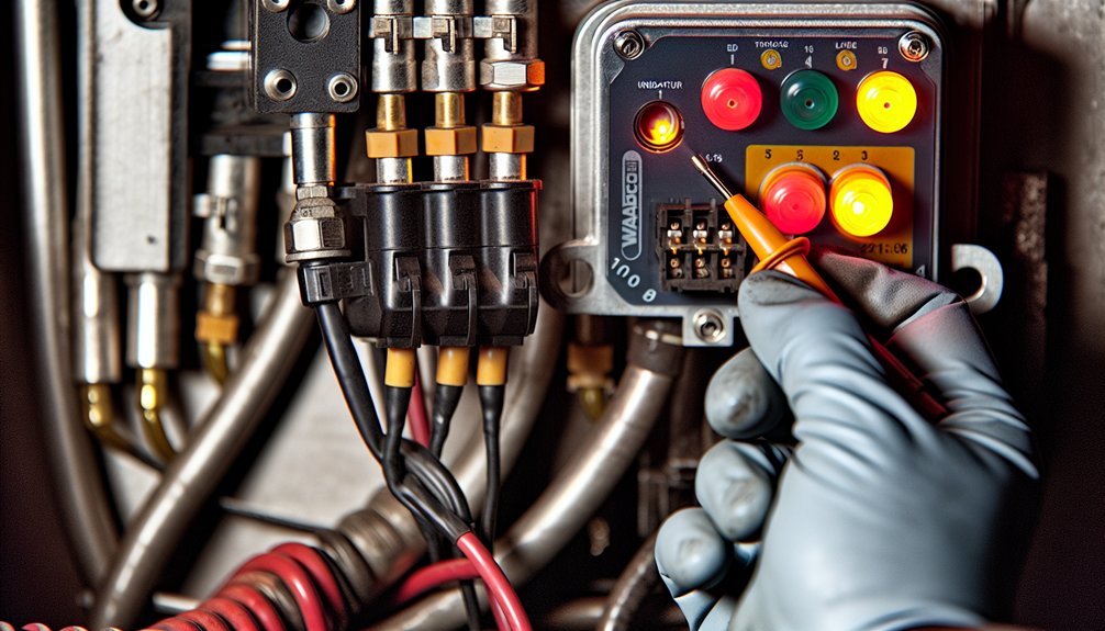
To troubleshoot the WABCO EPIC electronic brake interface on locomotives, always start with data. Connect the diagnostic tool. Pull active and historical J1587 fault codes before touching any component. This isolates electrical, pneumatic, and sensor‑related issues quickly.
From there, move to the wheel speed sensors. Check every sensor gap against WABCO locomotive specifications. Inspect tone wheels for damage or contamination. A small gap error can cause major EPIC braking issues under adhesion limits.
Next, examine wiring integrity. Inspect harnesses from the EPIC ECU to sensors and solenoid valves. Look for chafing, crushed sections, loose connectors, and corroded pins. Pay special attention near trucks, junction boxes, and high‑heat areas. Repair or replace damaged harnesses using proper locomotive‑grade materials.
Test solenoid valve function methodically. Use the diagnostic tool or manual activation methods specified for your locomotive. Confirm each valve responds correctly and vents or supplies air as commanded. Compare valve performance on suspect trucks with a known good truck, when possible.
Check the pneumatic side in detail. Use calibrated gauges on key test ports. Identify air leaks in brake pipe, control pipe, and cylinder circuits. Listen for leaks and apply soap solution where needed. Inspect diaphragms and seals in relay and control valves for damage that causes slow or lost pressure.
Evaluate heat exposure around the electronic brake cabinets. Look for discolored insulation, brittle wiring, or melted conduit. Confirm that cooling fans, louvers, and cabinet seals work properly. Persistent overheating can shorten EPIC ECU and valve manifold life.
Inspect for ECU moisture intrusion. Open cabinets only as allowed by safety procedures. Check gaskets, door alignment, and drain paths. Look for corrosion on connectors or PC boards. Moisture issues often present as intermittent, temperature‑dependent faults.
Verify locomotive power quality. Measure voltage at the EPIC ECU supply under different operating conditions. Watch for dips during engine cranking and spikes during load changes. Correct charging system faults, grounds, or loose power connections before condemning the ECU.
Each failure mode demands a specific fix. Sensor gap errors call for precise adjustment and secure mounting. Wiring issues require proper splicing, routing, and strain relief. Pneumatic leaks need seal replacement and torque checks. Heat and moisture problems demand cabinet and airflow corrections.
Work through each cause in diagnostic order. Do not skip steps, even if a likely culprit appears early. This disciplined sequence prevents repeat callouts and misdiagnosed ECUs. For replacements, use genuine WABCO locomotive brake components sourced through Mikura International. You will find every critical repair procedure covered in the detailed sections that follow in your maintenance program and OEM manuals.
Key Takeaways
- Retrieve active and historical J1587 fault codes from the ECU before beginning any physical inspection or repair work on the brake system.
- Inspect wheel speed sensor gaps first, setting the sensor-to-tooth wheel clearance between 0.2–0.5 mm using feeler gauges.
- Verify ABS solenoid coil resistance between 4.0–9.0 Ω and confirm operation within ±15% of rated supply voltage.
- Replace the WABCO EPIC Valve Assembly (part 05934471001) when brake response times exceed tolerances by more than 15%.
- After any ECU replacement, verify electrical connectors, inspect CAN data connections, run static locomotive tests, and update the maintenance log.
How the WABCO EPIC Electronic Brake Interface Controls Brake Pressure
- The WABCO EPIC system links electronic controls with pneumatic components on locomotives.
- It regulates brake pressure distribution across the entire locomotive consist.
- Its microprocessor-based design converts engineer commands into precise pneumatic responses.
- This reduces lag between operator input and actual brake reaction.
- Adaptive algorithms calculate optimal brake pressure for multiple axles.
- They prevent wheel lockup and maintain consistent braking during steep grade descents.
- Pneumatic operating units receive electronic signals from the control module.
- They proportionally regulate airflow to each brake cylinder.
- This enables smooth, graduated pressure application instead of simple on/off braking.
- Integrated sensors provide continuous feedback on brake line and cylinder pressures.
- They send real-time data to the central electronic control unit.
- Electronic feedback loops compare actual and target pressures.
- They correct deviations within milliseconds to maintain safe braking performance.
- Redundant electronic channels protect critical brake control functions.
- A dual-channel power supply maintains operation during certain electrical faults.
- These features support reliable and precise brake pressure control in modern locomotive applications.
- EBS communicates only on J1939, requiring a power cycle after any protocol change to re-establish adapter communication.
Read WABCO EPIC J1587 Fault Codes Before Touching Any Component

Before working on any WABCO EPIC system in a locomotive or marine engine, read the J1587 fault codes first.
Access the ECU and retrieve active and historical codes.
Study the patterns across all monitored wheel positions or axles.
Each PID–FMI combination narrows the root cause.
It shows if you face sensor calibration issues, wiring faults, or mechanical damage.
| PID Code | FMI Code | Indicated Fault |
|---|---|---|
| 0–4 (Wheel Position) | FMI 1 | Air gap exceeded, bearing wear |
| 0–4 (Wheel Position) | FMI 5 | Circuit open, corroded connector |
| 0–4 (Wheel Position) | FMI 4 | Short to ground, damaged insulation |
Fix ABS Warning Lights Triggered by Pressure Imbalance
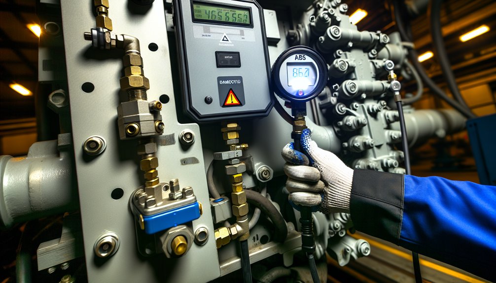
When an ABS warning light indicates pressure imbalance, you’ll need to systematically eliminate mechanical and electrical causes before suspecting the ECU or modulators. Start by inspecting wheel speed sensor gaps and tone ring alignment, since weak or intermittent signals frequently register as pressure deviation faults rather than actual hydraulic failures. From there, check connector integrity, solenoid valve condition, and grounding paths, as contamination, wiring faults, and voltage instability each independently trigger false pressure imbalance codes that clear once you’ve restored stable signal and power delivery. Uneven brake pad wear from misalignment can also produce false pressure imbalance readings, so verify pad condition and alignment before concluding that the fault originates in the electrical system.
Diagnosing Pressure Imbalance
- Focus on pressure sensor checks, air system leak detection, solenoid power verification, ABS modulator and ATC resistance, and wheel sensor gap.
- Begin by confirming the brake pressure sensor receives 8.0–16.0 volts DC.
- Check for sensor hysteresis that causes unstable or drifting pressure signals.
- Inspect all pneumatic or hydraulic coupling points along the brake circuit.
- Listen for air leaks or hissing when the brake system is applied.
- Verify each ABS solenoid operates within ±15% of its rated supply voltage.
- This prevents overheating, burnout, and nuisance ABS fault codes.
- Measure ABS modulator coil resistance between 4.0–9.0 ohms using a calibrated meter.
- Confirm ATC valve coil resistance stays within 7.0–14.0 ohms.
- Set the wheel speed sensor-to-tooth wheel gap between 0.2–0.5 mm.
- Incorrect gap can cause false speed readings and trigger ABS warnings.
- Moisture in air lines can degrade ABS and ATC performance and risk system freezing in cold weather conditions.
- Mikura International supports operators with components and guidance for stable locomotive and marine brake performance.
Restoring ABS System Balance
Next, complete sensor recalibration for the locomotive ABS. Confirm the Brake Pressure Sensor receives 8.0–16.0 volts. Ensure it transmits accurate signals to the ECU. Check solenoid valve resistance with a calibrated meter. ABS modulator valves must show 4.0–9.0 ohms. Active Braking Valves must show 7.0–14.0 ohms. Correct or replace any faulty components before proceeding. Reset the ECU using authorized TOOLBOX Software. Then cycle the locomotive ignition and monitor system status. Confirm pressure balance is restored across all brake circuits. This manual covers both ABS and ESC systems, making it a comprehensive reference for diagnosing interconnected brake control faults.
Repair Broken Wheel Sensor Wiring and Gap Misalignment

Broken wheel sensor wiring and gap misalignment are difficult to diagnose on locomotives. These faults are often intermittent. Fault codes appear, disappear, and reappear with vibration or temperature changes. Connector movement on a running locomotive can also trigger temporary faults.
Inspect sensor insulation near the brake assembly. Look for cracking, abrasion, or tension stress at every flex point. Damage here can cause intermittent open circuits during locomotive operation. Compromised magnetic shielding along the cable also creates problems. Electromagnetic interference can distort the sensor signal reaching the ECU.
For gap misalignment, verify sensor output at low wheel speed. Check the sensor produces at least 0.2V AC at 30 RPM. Anything lower indicates incorrect positioning relative to the tone ring. This can cause speed readings to drop out at low speeds.
- Check sensor cables at all flex points for broken conductors or damaged insulation
- Measure sensor-to-tone-ring gap with feeler gauges to match the locomotive manufacturer specification
- Clean tone ring teeth thoroughly and remove rust or debris
- Inspect for missing, worn, or impact-damaged tone ring sections before re-testing output voltage
Correct both wiring and gap issues before clearing fault codes in the locomotive control system. Regular sensor checks are recommended to ensure proper functionality and effective brake system intervention.
Clear Clogged Solenoid Valves in EPIC Valve Assemblies
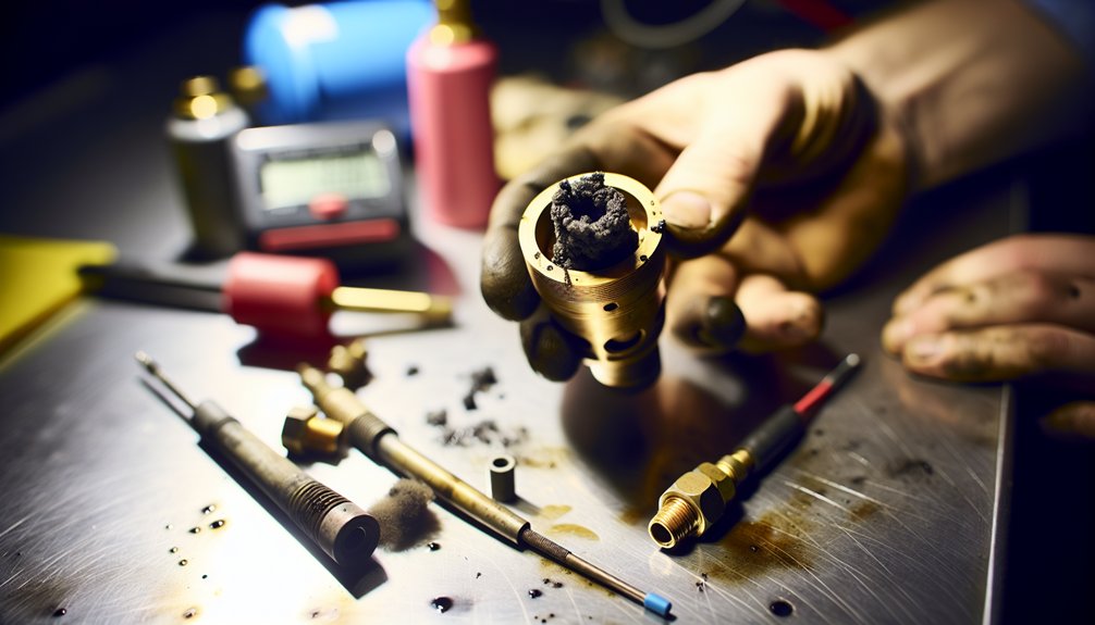
- Clogged solenoid valves in EPIC assemblies often result from moisture and oil in locomotive brake air systems.
- Solenoid valve clogs in EPIC assemblies trace back to moisture and oil contaminating locomotive brake air systems.
- Mineral deposits form as moisture dries inside the valve passages.
- Oil aerosols from the compressor also collect and harden in small orifices.
- These blockages trigger diagnostic trouble codes in the “7” or “8” series.
- Such codes indicate BC control and BC equalizing control failures on locomotive brake systems.
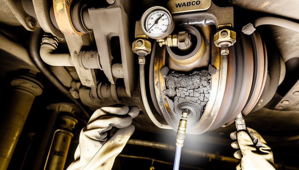
- Confirm obstruction using calibrated pressure gauges during brake application tests.
- Look for pressures that fail to reach specified values within the expected time.
- Inspect the exterior of the valve housing for staining and discoloration.
- Such marks can indicate internal corrosion and moisture exposure.
- Use clean, dry compressed air to flush valve passages at controlled pressure.
- Avoid excessive pressure that may damage seals or delicate internal parts.
- This step removes loose particles without affecting valve metallurgy.
- For hard mineral scale, use an ultrasonic cleaning bath on removed valve bodies.
- Alternatively, apply only pneumatic-approved chemical solvents for oxidized buildup.
- Observe manufacturer limits for temperature, exposure time, and compatible materials.
- Disassemble the EPIC valve assembly on a clean workbench.
- Inspect each orifice and passage under good lighting and magnification.
- Check coil insulation for burns, cracks, or swelling during the same procedure.
- Flush from the main reservoir and supply tank outlets toward the brake cylinders.
- This direction prevents debris from migrating back into cleaned components.
- Repeat the flushing until no contamination appears at the drain points.
- After cleaning, replace desiccant cartridges in the air dryer system.
- Service or replace air intake filters on the locomotive compressor as required.
- These steps reduce future moisture and oil carryover into EPIC valves.
- A master cylinder with an aluminum or steel body can serve as a reference point when evaluating material compatibility in hydraulic-adjacent pneumatic brake component replacements.
- Record all cleaning, parts replaced, and test results in the locomotive maintenance log.
- Verify correct operation through functional brake tests before returning the unit to service.
Find ECU Failures Caused by Water Intrusion and Voltage Spikes
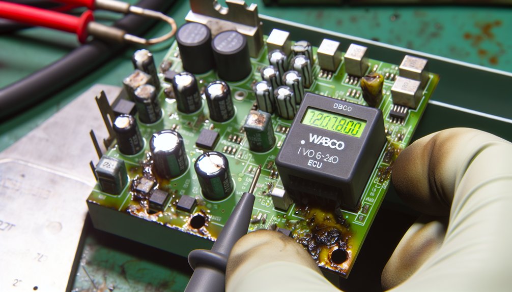
Water intrusion and voltage spikes can severely damage locomotive ECU brake systems.
Use a systematic approach to distinguish both failure modes.
Inspect all ECU connectors first.
Corroded connectors show white or green deposits on pins.
These often trigger intermittent fault codes 521 or 563.
Voltage spike damage looks different.
You may see burned PCB traces or cracked components.
Power transistors and drivers may fail without visible corrosion.
Calibration parameters can corrupt after transients above 20 volts.
Watch for these diagnostic patterns:
- Fault codes that disappear and reappear during wet weather suggest moisture in sensor cables.
- Multiple brake circuit faults at once point to power or ground degradation.
- Blown surge protection parts and damaged IGBTs indicate inductive spikes from solenoid valve switching.
After completing repairs, improve long‑term protection.
Apply silicone conformal coating on exposed ECU areas.
Use sealed connector designs to reduce future moisture ingress in locomotive environments.
Measure input voltage stability during deceleration events to identify supply drops that may contribute to recurring ECU faults.
Stop Air Leaks Destroying EPIC Brake Chamber Pressure
- Once you secure the ECU from moisture and voltage spikes, check air integrity next.
- Pressure loss in EPIC brake chambers reduces braking force.
- This creates serious safety risks for locomotives and marine engines.
- Begin with a static leak test on the air system.
- Measure system pressure drop with all controls in the run position.
- Allow pressures to stabilize before recording readings.
- Follow the OEM-recommended pressure drop limits for your locomotive or vessel.
- Use these as your baseline instead of road-vehicle standards.
- Apply a soap solution to all suspect joints and fittings.
- Watch for growing bubbles around unions, valves, and chamber ports.
- Growing bubbles confirm a high-pressure air leak.
- For complex pipe runs, use a dry ice fog method.
- Introduce fog into the line and follow any escaping vapor.
- This method helps trace hidden leaks in confined engine rooms.
- Prioritize typical failure points around EPIC brake chambers.
- Inspect for chafed hoses along bulkheads and under walkways.
- Check worn O-rings in valve blocks and connection manifolds.
- Look for cracked chambers on mounting brackets or support frames.
- Examine diaphragms for damage that vents air through chamber vents.
- Marine atmospheres and locomotive operating environments are harsh.
- Salt-laden air and humidity accelerate seal degradation.
- Apply suitable protective coatings on exposed metal surfaces.
- Use corrosion-resistant hardware where practical.
- Install moisture traps or air dryers in supply lines.
- These reduce water vapor buildup in EPIC brake chambers.
- Condensed water can freeze or carry debris into valves and seals.
- Replace failed diaphragms immediately after detection.
- Spring brake sections usually experience the highest stress.
- Piggyback sections can also fail under repeated cycling.
- Check mounting bolts for correct torque each maintenance cycle.
- Loose bolts can distort chamber housings and damage seals.
- Inspect glad-hand style or coupling seals in locomotive air lines.
- Hardened or cracked seals must be renewed without delay.
- Document all leaks found and repairs performed.
- Use this data to refine inspection intervals and spare parts planning.
- A saturated desiccant cartridge in the air dryer can cause the purge valve to stick open, allowing continuous pressure loss that undermines brake system integrity.
Replace Failed EPIC Diaphragm Seals Before Brake Chamber Pressure Fails
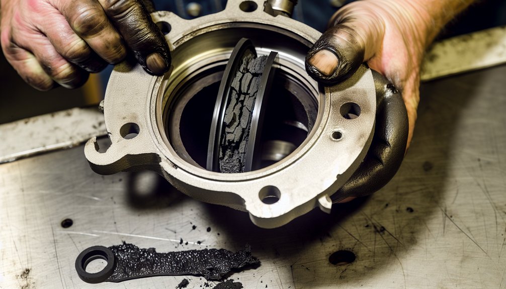
- Across EPIC brake chambers in locomotives, diaphragm seal failure is usually audible.
- You may hear hissing during service brake activation.
- After shutdown, pressure can drop 60–70 PSI within minutes.
- Cab warning indicators confirm pressure loss and imbalance.
- The compressor may struggle to maintain safe system pressure.
- Do not delay diaphragm inspection once these symptoms appear.
- Early checks prevent in-service failures on mainline or yard operations.
- During replacement, seal material selection is critical.
- High temperatures above 150°C reduce diaphragm elasticity by about 50%.
- Select heat-resistant compounds that match locomotive operating conditions.
- Always use high-quality, application-approved diaphragm seals.
- Torque cylinder head bolts to 25±5 Nm.
- This ensures even clamping and uniform pressure distribution.
- Perform pressure cycling tests at full governed speed.
- Verify control pressure reaches 7 bar at cut-off.
- Use regulatory compliance testing to identify specific chambers with deterioration.
- Document test results for each brake cylinder on the locomotive.
- Spring brake chambers can store 1,200–2,500 pounds of force.
- Use certified, specialized tools for safe disassembly and servicing.
- Cage bolt corrosion on spring brake chambers can lead to catastrophic release of stored spring energy if not inspected and replaced immediately.
- Proactive diaphragm replacement reduces stopping distance risks.
- It also minimizes costly unscheduled downtime and emergency repairs.
- For EPIC brake chamber parts and seal replacement support in locomotives,
- Mikura International can supply suitable components and technical guidance.
Fix Slow Brake Response From Heat-Damaged EPIC Components

- Heat damage affects EPIC brake components silently in locomotive and marine engines.
- Heat damage silently compromises EPIC brake components in locomotive and marine engines before any visible failure occurs.
- It degrades diaphragm elasticity, valve seals, and gaskets before failure becomes visible.
- Slow brake response usually appears after extensive thermal stress on these components.
- Temperatures above 150°C reduce diaphragm elasticity by nearly 50%.
- This reduction prevents proper diaphragm expansion during repeated brake engagement cycles.
- Run pressure drop tests at full governed engine speed in locomotives or marine engines.
- Confirm whether heat-damaged components can maintain the 7-bar cut-off threshold.
- Use thermal imaging during normal operation to locate abnormal hot spots.
- These hotspots help pinpoint specific EPIC components suffering from heat concentration.
- Implement protective measures immediately after confirming heat-related damage.
- Apply thermal coatings around modulator valves in the engine compartment.
- This reduces radiant heat absorption from nearby high-temperature engine sources.
- Use suitable coolant additives approved for locomotive or marine applications.
- They enhance circulation efficiency through brake-related cooling circuits and chambers.
- This helps keep component temperatures below critical limits during continuous braking.
- Maintain strict air-purging filter schedules in compressed air systems.
- This prevents oil carryover that accelerates seal and gasket degradation.
- Replace heat-compromised diaphragm seals and modulator valves in a controlled sequence.
- Follow the engine manufacturer’s recommended torque procedure for cylinder head bolts.
- Typically, torque values are around 25±5 Nm for many EPIC assemblies.
- Correct torque restores consistent pressure distribution within the brake system.
- Mikura International supports reliable sourcing of EPIC brake components for locomotives and marine engines.
Replace the WABCO EPIC Valve Assembly When Repairs Stop Working
When recurring DTCs persist after clearing memory bits, brake response times exceed tolerances by more than 15%, or stopping distances continue degrading despite calibration, you’ve reached the threshold where full valve assembly replacement becomes necessary. You’ll need to source part number 05934471001, the current WABCO Wabtec 30 A-CDW classification assembly, which maintains compatibility with your existing pneumatic piping and electrical wiring without requiring chassis modifications.
Once installed, you must verify all ECU electrical connectors, inspect CAN data connections, and run static locomotive test procedures to confirm the replacement assembly operates within specifications across all brake application modes. SPW Industrial provides a one-year warranty against defects in workmanship and material under normal use, covering the replacement assembly from the date of purchase.
Signs Replacement Is Necessary
Even after replacing ABS valves and individual components, some issues may continue.
Recurring air leaks and delayed brake response indicate deeper problems.
Persistent pressure imbalances can mean the WABCO EPIC Valve Assembly has reached the end of its service life.
Audible diagnostics and material testing help confirm this condition.
They show when diaphragm degradation exceeds acceptable repair thresholds in locomotive or marine braking systems.
You will recognize these critical failure indicators:
– Air Leak Persistence: Hissing from brake chambers during service activation shows serious internal leakage.
Pressure losses of 60–70 PSI within minutes indicate diaphragm seal failure beyond repair.
– Delayed Brake Response: Worn diaphragms cannot generate sufficient pressure quickly.
Brake response becomes sluggish in locomotive or marine applications.
Under temperature extremes exceeding 150°C, diaphragm elasticity may reduce by 50 percent.
– Dashboard Warning Activation: Pressure imbalances can trigger multiple warning indications.
Brake warning lights and low air supply alerts may appear on the operator’s display.
These conditions can cause DOT or FRA brake tests to fail on locomotives.
Marine engines using similar control systems can also show non‑compliance alarms.
A communication link failure between the micro air brake system and control modules may also appear as a dashboard fault message requiring immediate attention.
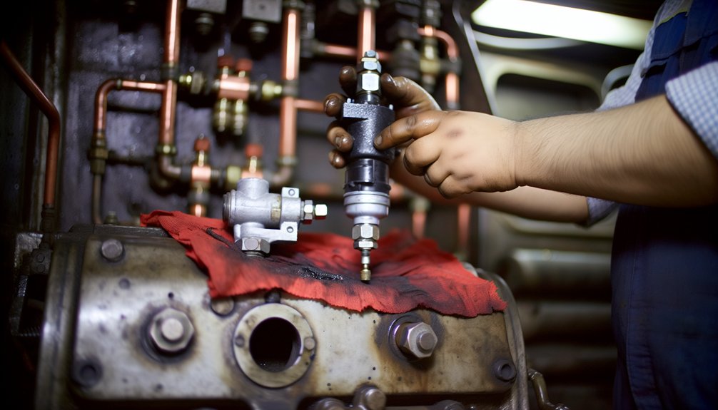
EPIC Valve Replacement Steps
Replacing the WABCO EPIC Valve Assembly becomes necessary when repairs no longer restore reliable brake performance on your locomotive.
Before starting, complete your safety checklist.
Park the locomotive on level track and secure it.
Chock the wheels and engage the parking brake.
Allow the air system pressure to fully bleed down.
To remove the old valve, first disconnect the wiring connector by hand.
Next, detach the Port 1 and Port 2 air lines carefully.
Remove both mounting capscrews and the corresponding nuts.
Install the new assembly using the original mounting location.
Secure the mounting hardware to the specified torque values.
Connect the Port 2 air line first on the locomotive brake system.
Then connect the Port 1 air line and check alignment.
Hand-tighten the wiring connector to avoid damage.
Once connected, apply the brakes and listen for air leaks.
Verify there is no pressure drop in the brake system.
Cycle the locomotive ignition to confirm proper valve cycling.
Perform a controlled test movement to verify ABS lamp operation.
Document the replacement in the locomotive maintenance log.