
Integrating the WABCO 26L brake assembly on a locomotive can be intimidating, especially when you’re worried about mis-plumbing, incorrect valve positions, or failing initial brake tests that delay a unit’s return to service.
Clear, step-by-step pneumatic and procedural guidance is essential to avoid rework, fault codes, and unsafe brake performance in yard or road service.
- Difficulty interpreting the 26L pneumatic control logic on complex locomotive brake schematics
- Uncertainty about correct reservoir and brake cylinder pressure ranges before installation
- Risk of installing non-OEM parts that compromise brake timing, tolerances, or regulatory compliance
- Confusion over proper positions of automatic and independent brake valves during setup
- Fear of trapping pressure in the system and creating unsafe conditions during integration
- Limited documentation that ties theory (valve sequencing) to practical shop-floor steps
- Concern about voiding warranty or failing railway safety inspections
- Need for a quick pre-integration checklist that technicians can follow under time pressure
| Pain Point | What to Check/Do | Target/Requirement |
|---|---|---|
| Unsure if system is safe to work on | Fully depressurize locomotive brake system | Gauge reading: 0 kPa where required |
| Correct main reservoir pressure range | Verify main reservoir pressure with calibrated gauges | 750–850 kPa |
| Risk of residual brake cylinder pressure | Confirm brake cylinder pressure prior to integration | 0 kPa (no residual pressure) |
| Incorrect automatic brake valve position | Set automatic brake valve handle | Release position |
| Incorrect independent brake valve position | Place independent brake valve | Extreme left (full release) |
| Using non-compliant parts | Verify components are genuine Wabtec OEM | OEM only for warranty and safety |
| Incomplete understanding of control logic | Review pneumatic diagrams and valve sequencing | Before any physical work |
To integrate the WABCO 26L brake assembly on a locomotive, you must first understand its pneumatic control logic, internal tolerances, and valve sequencing before any installation begins.
Start by fully depressurizing the locomotive brake system, verifying main reservoir pressure between 750–850 kPa, and confirming brake cylinder pressure reads zero.
Set the automatic brake valve handle to Release and the independent brake valve to its extreme left position.
Use only Wabtec OEM parts to maintain dimensional accuracy, regulatory compliance, and warranty validity.
Continue through this guide to master every critical step in safe, reliable locomotive brake integration.
Key Takeaways
- Before integration, vent main reservoir to zero psi, close isolation cocks, chock wheels, and set the locomotive handbrake.
- Verify main reservoir pressure (750–850 kPa), equalizing reservoir at 500 kPa, brake pipe matching equalizing reservoir, and brake cylinder at zero.
- Set the automatic brake valve handle to Release and place the independent brake valve handle at the extreme left Release position.
- The 26-F Control Valve manages competing air flow paths when both independent and automatic brake inputs are simultaneously applied.
- Use only Wabtec OEM parts and consult WABCO Maintenance Manual MM-0112 (pages 38 and 44) for diagnostics and assembly instructions.
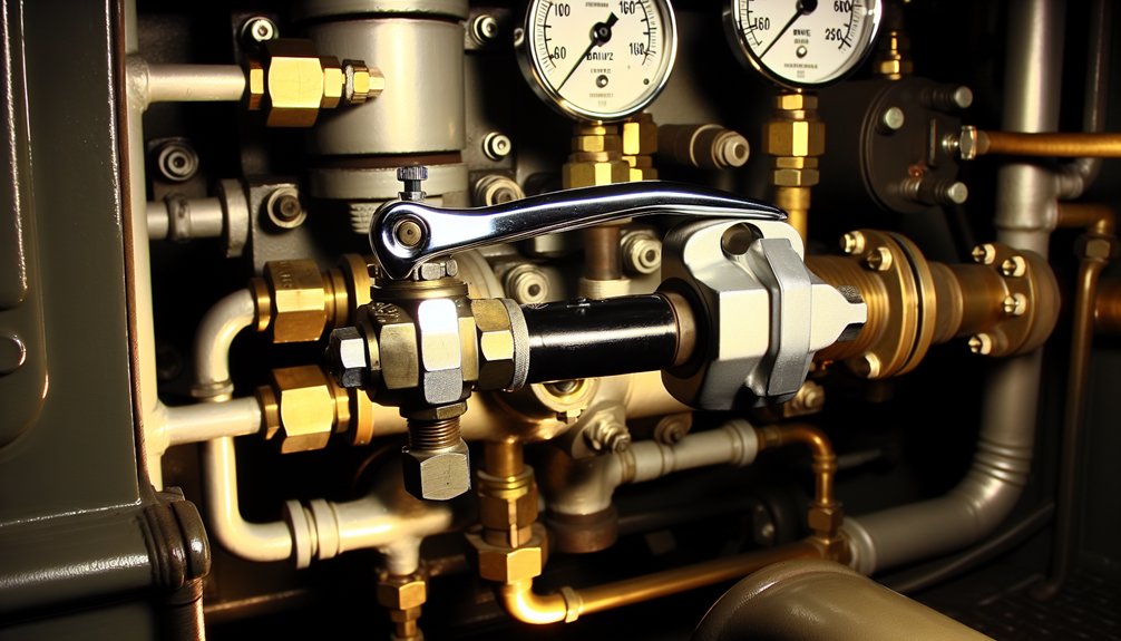
What Does the WABCO 26L Brake Valve Actually Do?

The WABCO 26L brake valve controls brake pipe pressure to activate control valves across every car and locomotive in the train consist. It regulates air distribution to deliver consistent braking force throughout the entire consist while modulating pressure to prevent wheel lockup during application phases.
You’ll rely on this valve to initiate service braking for controlled stops and trigger emergency sequences through rapid brake pipe venting when critical events demand immediate halts. Brake mode diagnostics become essential here — the valve maintains distinct air pathways for service versus emergency operations, ensuring each mode responds precisely to your inputs.
Operator feedback integration drives the valve’s pressure adjustment capability, allowing you to modulate system pressure within a defined range to match speed control commands. On steep descending grades, it maintains constant brake pressure automatically. This precise control architecture keeps stopping distances optimal while reducing ambiguity between braking modes during active operations. Wabtec engineers this valve as part of a broader commitment to delivering rail and industrial solutions that improve safety, efficiency, and productivity across demanding operational environments.
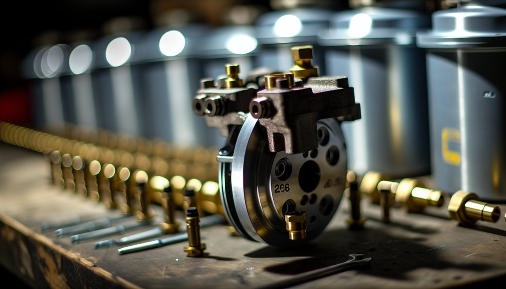
Unit Bodies, Cylinders, and Clevis Parts Inside the 26L
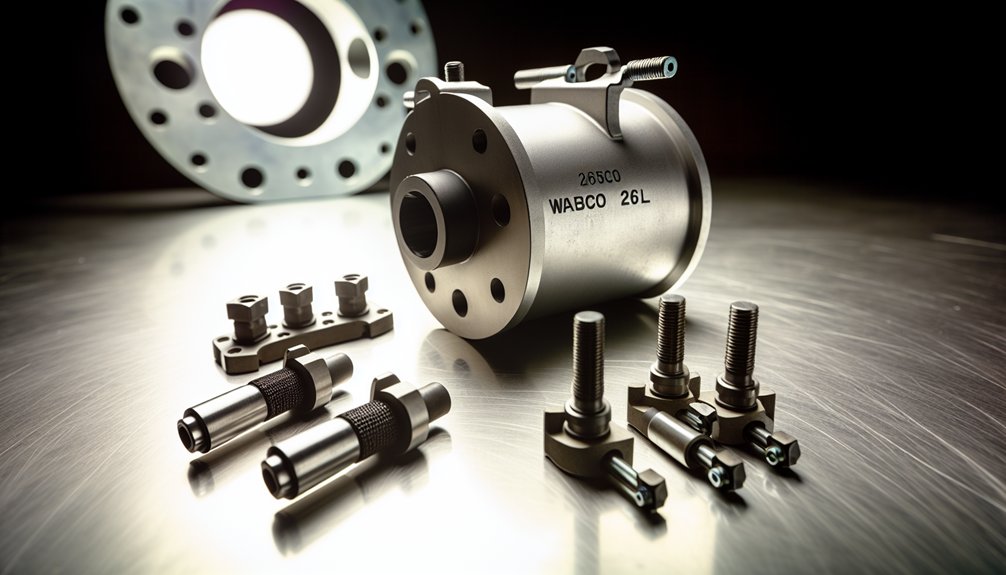
Cast iron forms the structural backbone of the 26L’s main valve body, machined to precise internal tolerances that regulate airflow between its separated automatic and independent brake chambers. Cast ironography durability defines this assembly’s longevity, as the hardened body outlasts internal sealing components by a factor of ten under standard operational conditions.
Inside the cylinders, pistons travel across honed bores, driven by pressure differentials that apply or release train brakes. Your piston sealants selection directly impacts system performance—synthetic rubber seals maintain airtight integrity while resisting degradation from compressed air contaminants. Spring-loaded mechanisms return valves to neutral when you release the handle.
Clevis assemblies bridge your external operating levers to internal valve stems through hardened steel pin connections. You’ll adjust clevis links to calibrate valve timing precisely. Retaining clips secure each pin, preventing disassembly during operation, while lubrication at clevis joints prevents seizing under repetitive cycling. The automatic brake valve controls train brakes through a six-position quadrant, meaning your clevis and lever geometry must accommodate the full range of handle travel across all defined stopping zones.
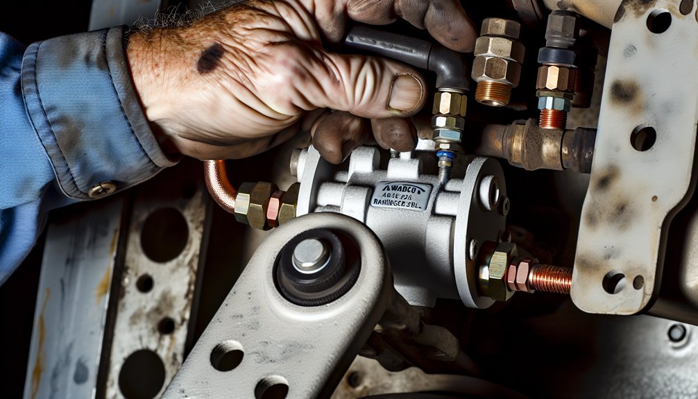
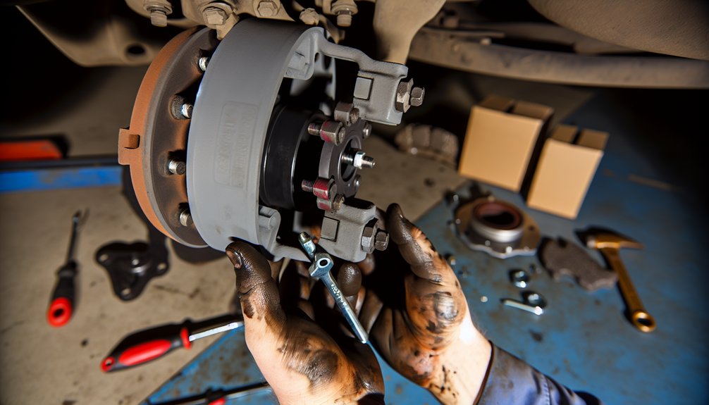
How to Prepare Your Locomotive for 26L Integration

Before you begin installing the 26L brake valve, you’ll need to depressurize and isolate the locomotive’s entire pneumatic system. Vent the main reservoir completely to zero psi, then close all isolation cocks on the brake pipe and equalizing reservoir lines. Chock the wheels and set the hand brakes to maintain unit stability throughout the procedure. Make certain adequate locomotive ventilation before venting, as crew safety depends on preventing pressure-related hazards in confined spaces.
Next, inspect the existing mounting bolts for corrosion or thread stripping before removal. Cap all control air supply lines immediately after disconnection to prevent contamination. Clean the brake stand mounting flange of old gasket material and oil residue, then verify the bolt hole pattern against the 26L base dimensions. Use a leveling instrument to confirm the mounting pad is within tolerance, and replace any cracked or compressed vibration isolation mounts before proceeding.
How the 26L Works Alongside the Independent Brake Valve
When you operate the 26L alongside the independent brake valve, you’re managing two distinct pressure control circuits that must coordinate without cross-interference. The independent valve transmits pneumatic signals directly to the locomotive’s brake cylinders, bypassing the brake pipe entirely, while the 26L’s automatic section governs brake pipe pressure across the full consist. You’ll need to understand how these pneumatic signal paths interact to maintain precise, conflict-free braking control during both independent and automatic applications.
Coordinated Pressure Control
The 26L system’s coordinated pressure control relies on the Independent Brake Valve operating alongside the automatic brake system to give you direct, isolated control over locomotive brake cylinders without disturbing train brake pipe pressure. When you apply both valves simultaneously, the 26-F Control Valve manages competing air flow paths, producing a combined cylinder pressure that reflects both inputs without conflict.
You can hold a specific automatic brake reduction while adding independent pressure for grade holding or enhanced stopping force. The dynamic brake interlock further prevents wheel slide by automatically reducing air brake pressure when dynamic braking engages. Once you release the independent valve, locomotive cylinder pressure returns precisely to the level your automatic brake setting dictates, restoring clean, predictable brake response across the consist.
Pneumatic Signal Transmission
| Function | Signal Behavior |
|---|---|
| Independent Release | Vents engine brake cylinder pressure only |
| Independent Apply | Directs main reservoir air to locomotive cylinders |
| Bailing Active | Exhausts local cylinder pressure; train line integrity maintained |
During airflow diagnostics, you’ll verify that each pathway operates without bleed-over. The equalizing reservoir retains pressure during bailing, keeping train brakes engaged while locomotive brakes release independently. The brake pipe maintaining feature prevents any unintended progressive increase in braking effort caused by reasonable brake pipe leakage during an application.
Independent Valve Integration
Building on how pneumatic signals route through the system, you’ll now need to understand how the Independent Brake Valve operates alongside the 26L’s automatic section as two distinct but coordinated control paths. The Independent Brake Valve applies force exclusively to locomotive brake cylinders, enabling locomotive isolation from train brake circuit responses.
This separation lets you hold constant cylinder pressure during grade descents without triggering control valves throughout the consist. Independent calibration guarantees your cylinder targets reach approximately 72 psi at full application without interfering with automatic brake pipe pressure. The 26L’s automatic section simultaneously manages brake pipe regulation across every car. You must verify these two paths remain pneumatically isolated; diaphragm compromise in the relay valve allows unwanted crossflow between independent and automatic circuits, degrading precise modulated control.
How to Install the WABCO 26L Brake Valve: Step-by-Step
Before mounting the WABCO 26L brake valve, you’ll need to confirm that your system meets all baseline pressure requirements. Verify main reservoir pressure reads between 750 and 850 kPA. Confirm the equalising reservoir gauge shows 500 kPA, and the brake pipe pressure gauge matches that reading. Brake cylinder pressure must indicate zero with the warning light off. Check that brake pipe flowmeter needles sit close together, confirming no active leaks.
Once pressure checks pass, apply the locomotive handbrake before proceeding. Position your mounting brackets correctly to guarantee component alignment during installation. Perform valve lubrication on all moving contact points before seating the assembly. Verify electrical grounding connections meet specification before energising any controls. Set the automatic brake valve handle to Release, place the independent brake valve handle at the extreme left Release position, then insert the reverser key into the direction slot. If the locomotive fails required tests, it must not enter service until all defects have been reported to and rectified by maintenance staff.
Hand Brake Adjustment Specs for the 26L Assembly
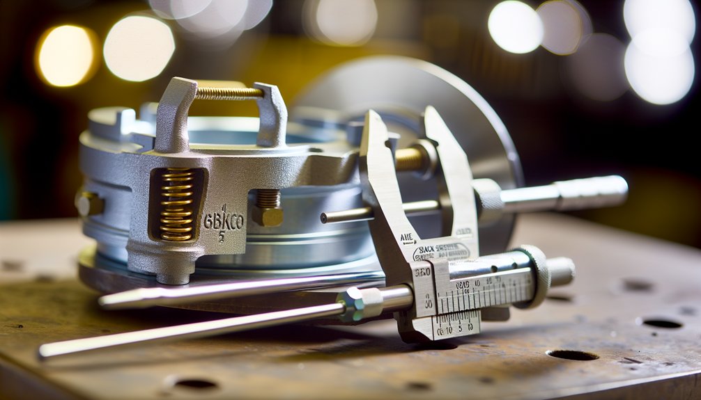
Although the WABCO 26L assembly integrates multiple braking subsystems, it doesn’t include dedicated hand brake adjustment specifications within its core documentation. Hand brake mechanisms and manual calibration procedures are treated as separate components, requiring you to consult manufacturer-specific manuals outside the 26-L system scope.
For reference, related heavy-duty brake specifications provide a useful baseline:
| Component | Specification | Application |
|---|---|---|
| Slack Adjuster | 6-inch | 26,000-lb rated systems |
| Brake Chamber | 30/30 long stroke | Heavy load configurations |
| Cast Drum | 120-lb minimum | 26,000-lb brake demands |
When verifying parking torque compliance, cross-reference Hendrickson technical bulletin L1097 alongside your vehicle’s OEM manual. Since Instruction Pamphlet No. 74 omits parking brake metrics entirely, you’ll need supplementary documentation to complete any manual calibration process accurately. Always block wheels before beginning any adjustment work. The WABCO Maintenance Manual MM-0112 covers diagnostics and component replacement across sections beginning on pages 38 and 44 respectively, offering broader system context that may inform adjacent brake assembly procedures.
26L Installation Errors and How to Fix Them
When integrating the 26L assembly, you’ll encounter installation errors that typically fall into three categories: improper component seating, incorrect air line routing, and mismatched electrical connections. You can diagnose pressure failures by checking for voltage supply within the 9.0–16.0 volt operating range, verifying valve resistance values, and confirming that all connectors are fully seated before cycling the system. Once you’ve identified the fault source, correct it by following torque specifications, clearing residual blink codes from ECU memory, and re-testing under controlled conditions to confirm the system’s restored integrity. Always release all air pressure before disconnecting any components, as pressurized air can cause serious personal injury during the correction process.
Common Installation Mistakes
Even experienced technicians make critical errors during WABCO 26L brake assembly installation, and understanding these failure points is essential to preventing costly rework and component damage. Mistakes often stem from improper sealant selection, skipped verification steps, and improper bedding procedures that compromise system integrity from the start. Always reference the latest assembly and maintenance instructions, as new versions are available through WABCO’s INFORM system at www.wabco-auto.com.
Watch for these four critical mistakes:
- Using standard grease instead of WABCO-approved high-temperature synthetic lubricant, causing slide pin seizure.
- Installing brake pads without verifying correct orientation, producing uneven wear and reduced braking efficiency.
- Cross-threading air line fittings, creating pressure leaks that compromise system integrity.
- Skipping pad and disc bedding, reducing initial braking performance and causing surface glazing.
You’ll avoid costly failures by addressing each mistake methodically before road testing begins.
Diagnosing Pressure Failures
Pressure failures after a WABCO 26L installation often trace back to electrical and pneumatic faults that are straightforward to isolate once you know where to look. Start with voltage diagnostics: confirm your brake pressure sensors receive 8.0 to 16.0 volts and that ECU supply stays within 9.0 to 16.0 volts. Low vehicle voltage triggers false pressure fault codes, so don’t overlook it.
Next, verify sensor continuity between the signal pin and both ground and power sources. On the pneumatic side, inspect M16x1.5 threaded connections on the foot brake valve for leaks and confirm air lines to the 26C assembly aren’t kinked. Open or shorted ABS valve ground connections cause immediate pressure faults, so test each diagonal before clearing codes from ECU memory. Sensors are recognized as essential components for braking system performance and vehicle safety monitoring, making accurate diagnostics critical to restoring proper pressure function.
Corrective Adjustment Procedures
Isolating a pressure fault gets you halfway there-fixing the root cause at the mechanical, electrical, or pneumatic level is the other half. Apply corrections systematically:
- Torque carrier bolts to specification-incorrect adjustment torque distorts brake assembly geometry and misaligns guide pins.
- Verify pad centering by confirming caliper orientation; improper positioning causes uneven wear and restricted lateral movement.
- Inspect pneumatic lines for crossed routing between front and rear valve packages, leaking fittings, and missing gaiters that admit moisture.
- Test electrical integrity by checking ABS valve ground connections on both diagonals, measuring Active Brake Valve resistance (7.0–14.0 ohms), and confirming ECU connector condition.
Correct each fault before clearing codes-unresolved issues mask active errors during post-installation diagnostics.
Why Only Wabtec OEM Parts Are Approved for 26L Repairs
When maintaining the WABCO 26L brake assembly, you’ll find that only Wabtec OEM parts carry approval for repairs — and that distinction isn’t arbitrary. Genuine components exit the supply chain with verified parts authentication, confirming each unit passed WABCO’s internal quality control processes before installation.
Non-genuine alternatives frequently exhibit dimensional discrepancies that compromise fitment with service valves, emergency valves, and control chambers. Those tolerances aren’t negotiable – the 26L’s modular design demands exact geometry to prevent leaks, pressure loss, or inoperative brakes during emergency applications.
Beyond compatibility, using non-approved parts voids warranty coverage and shifts liability directly to the operator following brake failure incidents. Regulators mandate validated components precisely because aftermarket substitutes routinely fail safety audits.
Every genuine Wabtec part also undergoes end-of-line functionality testing, ensuring operational readiness immediately upon installation and maintaining the braking performance integrity the 26L system requires. Operators also benefit from access to a worldwide customer service network of thousands of authorized dealers and workshops, providing support throughout the service life of the brake assembly.
Frequently Asked Questions
Can the 26L Integrate With Electronic Trailer Brake Control Modules?
Maintenance costs drop 75% with modern systems, so you can’t afford signal compatibility gaps. You cannot directly integrate the 26L with electronic trailer brake control modules. The 26L generates pneumatic pressure signals, not digital outputs, creating critical control latency issues that EBS modulators can’t process. You’ll need intermediate conversion hardware or a CCB-26® upgrade to translate pneumatic signals into ISO 11992-compliant digital communication your electronic trailer brake system requires.
Which Related Pneumatic Valves Are Compatible Alongside the 26L System?
You’ll find several pneumatic valves compatible with the 26L system. You can integrate relay valves to amplify brake cylinder pressure signals across longer train consists. Proportioning valves help you regulate pressure distribution between axles for balanced braking performance. Additionally, you’re able to assemble independent brake valves, emergency brake valves, and pneumatic control modules alongside the 26L, creating a cohesive, modular braking architecture that meets stringent operational standards.
How Does the Smartboard Interface Display 26L Brake Status and Errors?
The SmartBoard interface displays 26L brake status through display icons and status LEDs that update in real time as conditions change. You’ll navigate to the Diagnostic Memory menu to review diagnostic logs containing stored error codes ranging from 001 to 246. Codes like 007 identify relay valve solenoid faults, while 075 flags wear sensor failures. You can scroll chronologically through saved fault messages using the “Next” and “Previous” navigation buttons.
Can the 26L Be Used With Desktop-Mounted 30A-CDW Brake Valve Configurations?
You can’t directly replace the 26L’s automatic brake function with the 30A-CDW due to fundamental valve mounting differences. The 30A-CDW’s desktop compatibility suits a consolidated surface layout, while the 26L requires a vertical quadrant stand. You’d typically integrate the 30A-CDW alongside an Independent Brake Valve rather than substituting it. Both systems share brake pipe pressure principles, but their physical configurations and operational mechanics remain distinctly incompatible for direct replacement.
How Does the Emergency Brake Valve Interact With 26L Brake Pipe Venting?
When everything’s at stake, the emergency brake valve triggers immediate emergency venting, rapidly depleting the 26L brake pipe to near-atmospheric pressure. You’ll see the pressure wave propagate instantly through the pipe, commanding maximum braking force across all control valves. The system’s architecture prevents pipe backflow, ensuring unrestricted, unmodulated airflow evacuation. Service functions are completely bypassed, synchronizing locomotive and car brake applications simultaneously for the shortest possible stopping distance.