
You’ll fix most train brake assembly issues by addressing five key areas: replace worn brake pads showing tapered or wedge patterns from sticking caliper pins, repair air system leaks using soapsuds testing and complete line replacement rather than patching, disassemble and rebuild triple valves with new seals and proper spring tension, recalibrate J-relay valves for extreme weather with temperature-resistant elastomers, and clear auxiliary vent port blockages causing emergency activations. These systematic procedures guarantee reliable braking performance and safety compliance.
Key Takeaways
- Replace brake pads showing tapered wear, material detachment, or thermal degradation and service sticking caliper slide pins.
- Perform pressure drop tests not exceeding 5 psi per minute and use soapsuds testing to locate hydraulic leaks.
- Calibrate air flow meters every 92 days maintaining 90 psi brake pipe pressure with certified AAR S-5598 orifice.
- Disassemble triple valves, replace gaskets and seals, adjust spring tension, and pressure-test before reinstalling assemblies.
- Install weather-resistant seals, desiccant cartridges, and heated air lines to prevent moisture and ice formation issues.
Diagnosing Brake Pad Wear Patterns and Material Defects

When you encounter brake performance issues, examining pad wear patterns reveals critical information about underlying mechanical problems that compromise train safety. Tapered wear patterns indicate caliper mobility issues where sticking slide pins or worn bushings force the caliper to twist during application. This creates wedge-shaped wear as one end becomes noticeably thinner than the other.
During caliper inspection, check for uneven pressure distribution between inner and outer pads. When outer pads wear more than inner ones, the caliper isn’t releasing properly. Material detachment occurs when friction surfaces separate from backing plates, often revealing adhesive residue underneath.
Thermal degradation analysis identifies overheating damage that appears as porous friction material. Constant thermal stress accelerates deterioration and causes mechanical overloading beyond design specifications. Heavy corrosion at contact surfaces reduces effectiveness and creates uneven wear patterns. Dark or debris-filled brake fluid often signals broader hydraulic system issues that contribute to pad degradation. Systematic diagnosis of these wear characteristics determines whether caliper components, environmental factors, or thermal stress caused the degradation.
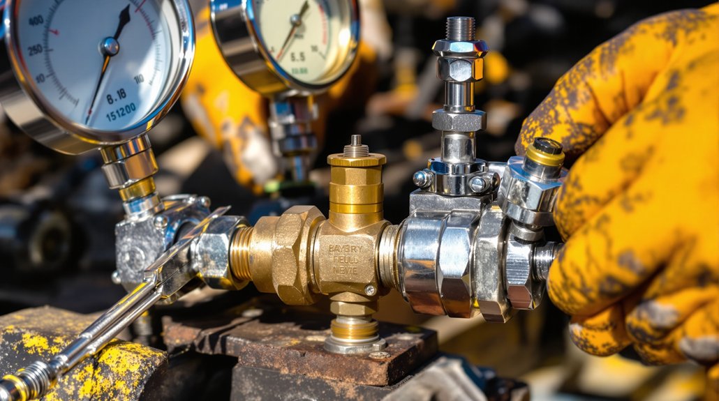
Resolving Air System Pressure Loss and Flow Rate Problems
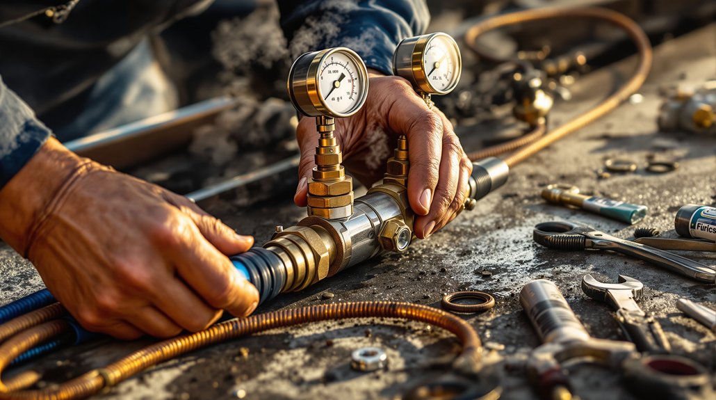
You must conduct systematic brake pipe leakage testing to identify pressure loss points that compromise system integrity and safety performance. Start by performing the standard one-minute pressure drop test, ensuring losses don’t exceed 5 psi per minute while monitoring all connections with soap solution or electronic detectors. Calibrate your air flow testing equipment every 92 days to maintain accuracy within 3 psi of the locomotive brake pipe gauge at 90 psi operating pressure. Address any pressure loss issues immediately upon detection, as early intervention typically results in less expensive repairs and prevents safety-related system failures.
Brake Pipe Leakage Testing
Pinpointing brake pipe leakage requires systematic testing to guarantee your train’s air system maintains proper pressure and flow rates throughout the consist. You’ll perform either traditional drop pressure testing or air flow method testing during scheduled testing intervals. For drop pressure tests, charge your brake pipe to within 15 psi of setup pressure, make a 20-psi service reduction, then monitor for one minute with the cutoff valve closed.
Leakage can’t exceed 5 psi per minute. The air flow method requires maintaining 75 psi minimum at the rear car while measuring flow rates under 60 CFM. AFM indicators must be calibrated every 92 days and meet accuracy standards to ensure reliable measurements. Document all leak detection results through proper record keeping procedures. Failed tests require immediate source location, repair, and retesting before operation.
Air Flow Calibration
Setting up proper air flow calibration eliminates pressure loss and flow rate problems that can compromise your train’s braking performance. You’ll need to calibrate air flow indicators every 92 days to prevent sensor drift and maintain federal compliance. During calibration scheduling, make certain your main reservoir pressure reaches 130-140 psi while maintaining 90 psi brake pipe pressure throughout the process.
Your calibration accuracy must stay within ±3 CFM at 60 CFM air flow, with testing temperatures not less than 20°F. Install the certified AAR S-5598 orifice to your front brake pipe hose glad hand for precise measurements. Always verify that brake pipe leakage stays under 5 lbs/min to ensure system integrity during calibration procedures.
- Document calibration dates on Form F6180-49A and record values in MEMS using task T-0044
- Set automatic brake valve to RELEASE position during flow meter testing procedures
- Use bypass needle valve adjustments to correct readings outside specification ranges
- Tag non-compliant indicators as “inoperative” until proper calibration is completed
Repairing Brake Pipe Leaks and Hose Assembly Failures
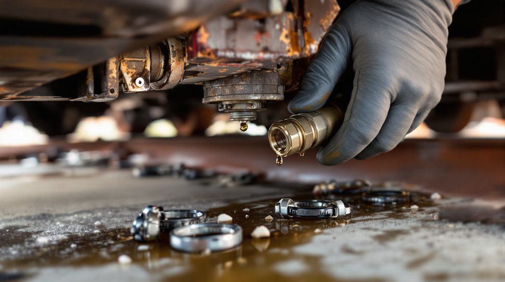
Detecting brake pipe leaks requires systematic testing using either the traditional pressure drop method or the air flow measurement technique to guarantee your train’s braking system meets regulatory safety standards. You’ll charge the brake pipe to within 15 psi of setup pressure, then monitor for leakage exceeding 5 psi within one minute or air flow above 60 cubic feet per minute.
When you’ve identified leak sources through soapsuds testing, you’ll find most failures occur at fitting connections due to ferrule corrosion or improper hose routing causing stress concentrations. Replace damaged line sections completely rather than attempting patches on rust holes in untreated steel lines. Install compression fittings with dual ferrules by slipping them over the pipe and tightening securely. WABCOSEAL components provide reliable sealing for fitting assemblies. Before installing any fittings, clean the wire and pipe thoroughly with sandpaper to remove corrosion and ensure proper sealing. You must locate and repair all leak sources before repeating CFR 232.205(c) compliance testing.
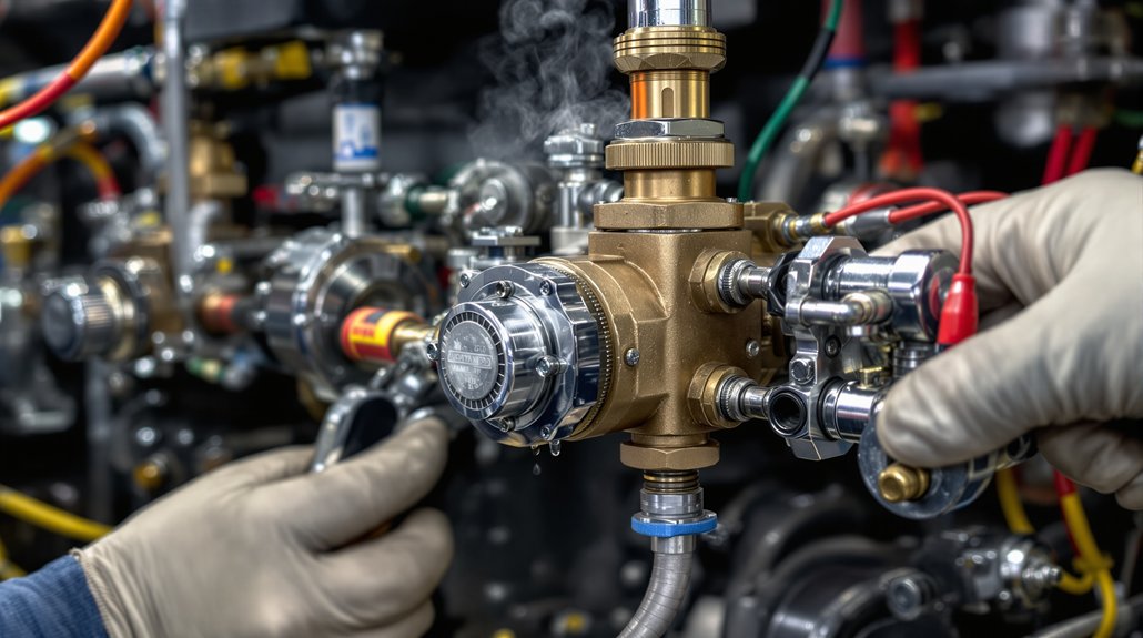
Troubleshooting Triple Valve and Control Component Malfunctions
When you encounter triple valve malfunctions, you’ll need to systematically diagnose whether the issue stems from internal component wear, contamination, or cold weather-induced failures. Start by performing daily air brake checks to identify valve defects that directly impact braking distance, force, and system response times. Address cold weather emergencies immediately, as New York Airbrake DB-10 components that exceed their useful life period can prevent emergency brake engagement when temperatures drop. Proper maintenance procedures involve replacing gaskets and service portions by removing three bolts, with rebuild costs estimated at approximately $180 per valve.
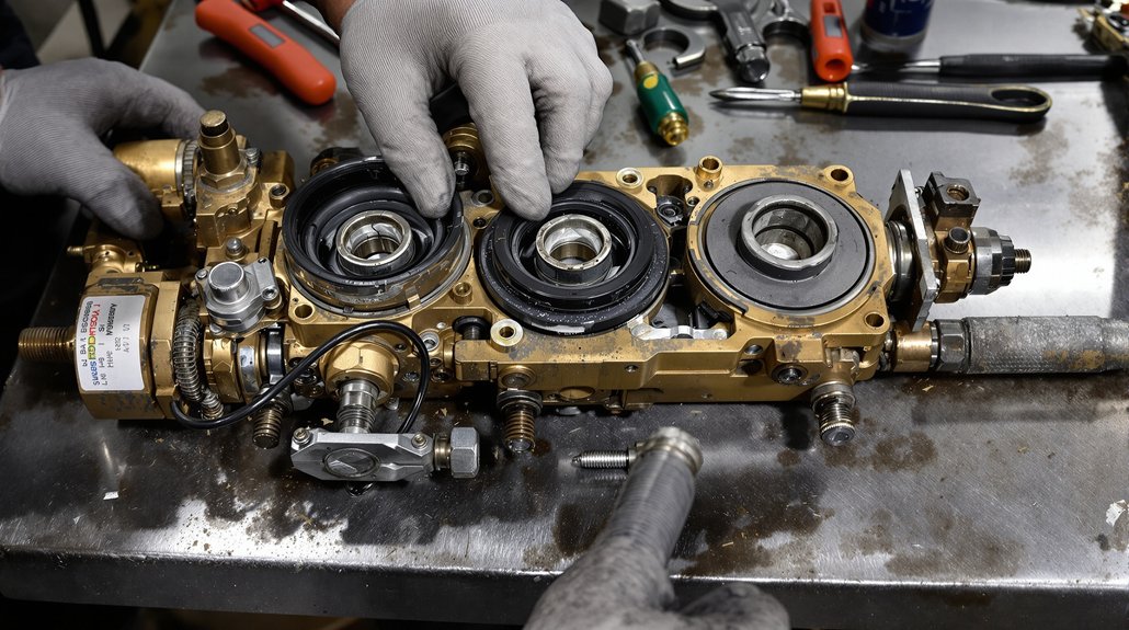
Triple Valve Repair Methods
Diagnosing triple valve malfunctions requires systematic testing of each component within the brake control assembly to isolate the root cause of pressure irregularities or response failures. You’ll need to perform valve lapping procedures to restore proper seating surfaces and eliminate air leaks that compromise braking performance. Pressure balancing verification guarantees the service and emergency portions operate within specified parameters.
Essential repair procedures include:
- Disassembly and cleaning – Remove valve components and clean all surfaces with approved solvents
- Gasket and seal replacement – Install new O-rings and sealing elements to prevent air leaks
- Spring tension adjustment – Calibrate spring forces to manufacturer specifications for proper valve timing
- Pressure testing – Verify operation at minimum and maximum working pressures before reassembly
Proper torque specifications prevent over-tightening that damages valve seats. When traditional repair methods prove insufficient, consider valve replacement as an alternative solution for severely damaged components that cannot be restored to operational standards.
Cold Weather Component Solutions
Cold weather conditions compound triple valve repair challenges by introducing thermal stresses that affect component tolerances and seal integrity. You’ll need to address specific cold-weather vulnerabilities in brake control systems when temperatures drop below 40°F.
| Component | Cold Weather Issue | Solution |
|---|---|---|
| O-rings/Seats | Pass shop tests but fail in field | Pre-cooling validation testing |
| Air Valves | Insufficient emergency pressure | Cold-weather seal materials |
| Couplings | Ice formation on connection faces | Coupling heaters installation |
| Switches | Reduced lubrication efficiency | Specialized lubricant selection |
| Metal Parts | Increased brittleness and fatigue | Enhanced inspection protocols |
Your lubricant selection must account for viscosity changes at freezing temperatures. Install coupling heaters to prevent ice accumulation on mechanical and pneumatic connections. Test all components at actual operating temperatures, not just heated shop environments. Brake components experience accelerated ice formation when heated elements like brake systems melt snow and cause rapid refreezing in subzero conditions.
Correcting J-Relay Valve Performance in Extreme Weather Conditions
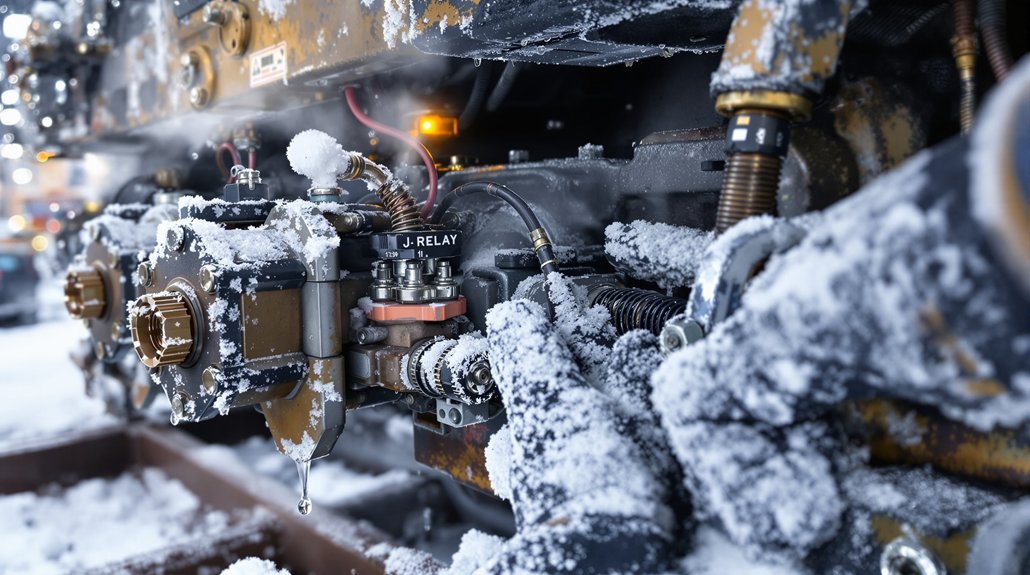
Although J-Relay valves function reliably under normal operating conditions, extreme weather exposes them to performance degradation that can compromise your train’s braking efficiency. Temperature fluctuations cause thermal glazing on valve seats, reducing sealing effectiveness and creating air leakage. You’ll need to implement proper valve insulation protocols to maintain consistent operating temperatures.
- Temperature compensation adjustments – Recalibrate valve spring tensions to account for material expansion and contraction rates
- Moisture elimination systems – Install desiccant cartridges and heated air lines to prevent ice formation in valve chambers
- Seal replacement protocols – Use weather-resistant elastomers rated for your operating temperature range
- Diagnostic pressure testing – Perform weekly valve response checks during extreme weather periods
Monitor valve response times closely during temperature extremes. Replace degraded seals immediately when you detect pressure drops exceeding manufacturer specifications. Position relay valves near the axles they serve to minimize control air transmission delays that worsen in cold conditions. Regular preventive maintenance prevents catastrophic brake system failures that could endanger operations.
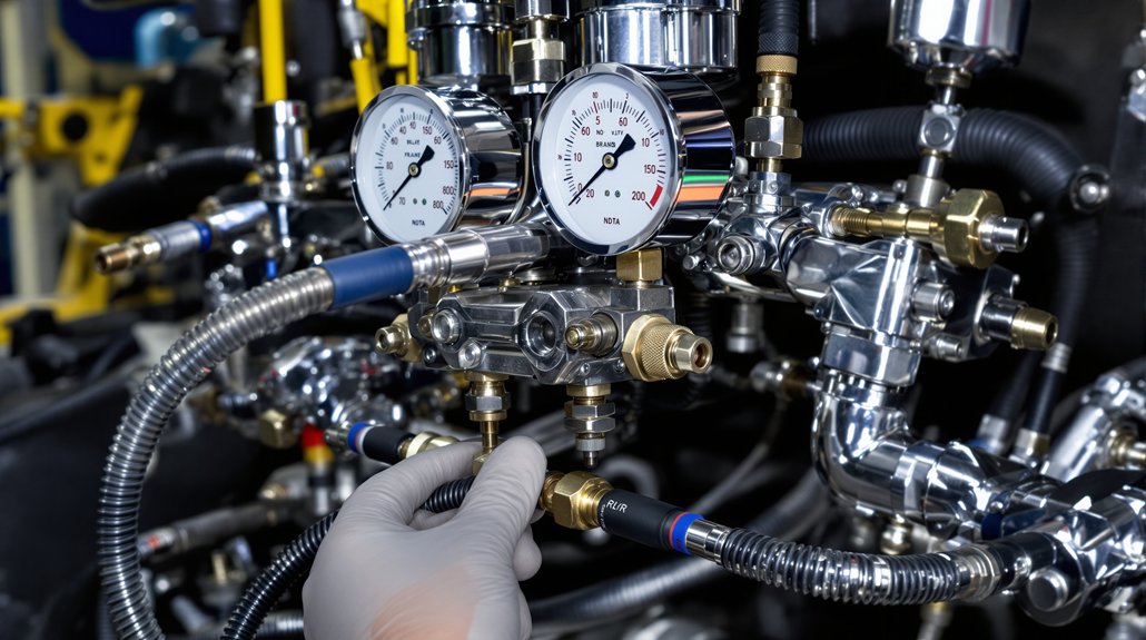
Calibrating Flow Meters and Bypass Needle Valve Adjustments
Beyond routine brake system maintenance, flow meter calibration represents a critical safety procedure that you must perform every 92 days to meet federal compliance standards. You’ll need to verify brake pipe leakage stays below 2 psi per minute and maintain main reservoir pressure between 130-140 psi before beginning calibration.
Install the certified AAR S-5598 orifice at your front brake pipe hose glad hand, then position your automatic brake valve to RELEASE mode while maintaining 90 psi brake pipe pressure. Your pressure sensors must read within 3 psi of the locomotive brake pipe gauge during testing. Conduct flow diagnostics to guarantee readings fall within the 59-61 CFM specification range.
If readings exceed specifications, adjust the bypass needle valve on your meter base. The magnet valve controls brake pipe exhaust through the predetermined orifice diameter, allowing precise flow calibration. Regular calibrations ensure your brake system measurements continue to meet device specifications as required by federal safety regulations. Document all pre-calibration and post-calibration values in MEMS using task T-0044.
Addressing Emergency Brake Activation and Auxiliary Vent Port Issues
When emergency brake activation occurs unexpectedly, you must immediately assess whether the system triggered due to mechanical failure, operator error, or external factors before attempting any reset procedures. Begin vent diagnostics by checking auxiliary vent ports for proper airflow and debris blockage that could compromise system pressure regulation.
Immediate assessment of emergency brake triggers—mechanical failure, operator error, or external factors—must precede any reset attempts or vent diagnostics.
Your emergency reset protocol requires complete system inspection before brake release. The emergency valve prevents brake recharge until you manually intervene, ensuring safety protocols aren’t bypassed. Check brake wire grounding connections, as emergency activation grounds these wires to prevent false-feed voltage from prematurely releasing brakes.
Critical diagnostic steps include:
- Inspect brake hoses between cars for cracks or disconnections causing unintended applications
- Verify emergency air valve response time meets one-second activation standard
- Test auxiliary vent port pressure regulation and debris clearance
- Examine wheel slide protection systems for proper calibration and response
Complete your emergency reset only after confirming all mechanical components function properly and investigating the root cause.
Implementing Preventive Maintenance for Reservoir Charging Systems
After resolving immediate emergency brake issues, you’ll prevent future system failures by establishing thorough maintenance protocols for reservoir charging components. Document all maintenance activities with systematic tracking of air compressors, reservoir tanks, and control valves. Establish daily air brake checks to guarantee safe operation and monitor brake pipe pressure equalization when all system pressures reach equal levels.
| Component | Monitoring Frequency | Key Parameters |
|---|---|---|
| Air Compressor | Daily | Compressor sequencing cycles |
| Reservoir Tanks | Daily | Pressure equalization levels |
| Control Valves | Weekly | Leak detection at connections |
| Brake Chambers | Weekly | Reservoir telemetry data |
Conduct leak detection procedures focusing on brake pipe leakages in hose assemblies and angle cock connections. Implement system leakage testing with valves in release position to identify reservoir and control valve issues beyond brake pipe problems. Monitor charging requirements where 70-car trains need approximately 9 seconds for minimum reduction service applications.
Frequently Asked Questions
How Often Should Brake System Components Be Replaced on Different Train Types?
You’ll need to follow specific service intervals based on your train type. Passenger coaches with AB-type systems require overhauls every 2,208 days, while 26-C systems need maintenance every 1,476 days. Freight locomotives need servicing every 3,680 days maximum. Electric and DMU trains vary from 1,104 to 1,840 days depending on brake system type. Component lifespans dictate replacement schedules regardless of apparent condition for safety compliance.
What Are the Typical Costs for Major Brake Assembly Repairs and Replacements?
You’ll face major brake assembly costs ranging from £2,700 to £7,320 over 2.57 million kilometers, depending on your component choices. Individual disc replacements cost £2,000 each, while complete sets reach £100,000. Labor costs materially impact your total expenses during scheduled maintenance windows. Parts markup varies between standard £40 pad sets and premium £50 options. You’ll minimize costs by coordinating brake overhauls with bogie maintenance schedules.
Which Brake System Manufacturers Provide the Most Reliable Components for Freight Operations?
Like a fortress built on bedrock, Knorr-Bremse‘s 50% Japanese market dominance demonstrates unshakeable reliability in freight operations. You’ll find their pneumatic systems deliver consistent performance across demanding applications. Wabtec Technologies complements this leadership with their TMX system‘s 250,000+ units sold worldwide and AAR S-4005 unconditional approval. You should prioritize these manufacturers when specifying brake components, as their proven field histories and reorder rates above 30% indicate superior long-term operational dependability.
How Do Weather Conditions Affect Brake Performance in Different Geographic Regions?
You’ll encounter varying brake performance challenges across different regions. In cold climates, ice accumulation degrades braking efficiency while snow creates adhesion problems between -5°C and 0°C. Coastal corrosion accelerates component wear due to salt exposure. High humidity above 80% increases friction coefficients unpredictably, while temperatures exceeding 200°C cause multiple wear patterns. You must adjust maintenance schedules and material specifications based on your specific geographic operating conditions.
What Training Certifications Do Technicians Need for Brake System Maintenance Work?
While many think on-the-job experience alone suffices, you’ll need proper certifications for brake maintenance work. You must obtain ASE certification in Brakes (A-5) after completing two years of hands-on experience and passing written examinations. Signal training becomes essential for understanding brake system diagnostics. Federal regulations require completing state or federal training programs, maintaining documentation throughout employment, and recertifying every five years to guarantee safety compliance.