
You’ll replace EMD traction motor suspension bushings by first removing the bogie assembly after disconnecting traction motor cables, brake gear, and body traction rods. Extract rubber-to-metal bonded traction rod bushings (document 40036366) and motor nose link bushings (document 40076633) using specialized hydraulic pullers, ensuring new components meet radial load ratings up to 11,000 kg. Install replacements per EMD torque specifications—320 ft-lbs for 3/4-10 fasteners—then verify assembly integrity through vibration analysis and insulation resistance testing. The following sections detail complete inspection protocols and model-specific requirements.
Key Takeaways
- Motor nose link bushings must meet radial load ratings up to 11,000 kg and operate from -10°C to 60°C per EMD specifications.
- Consult EMD service manual documents 40036366 and 40076633 to verify correct bushing specifications and material traceability before replacement.
- Use vibration analysis in 25–100 kHz range and thermal imaging to detect bushing deterioration before catastrophic failure occurs.
- Ensure replacement bushings use rubber-to-metal bonded construction compatible with WDG4, WDG4D, WDP4B, and WDP4D locomotive models.
- Document disassembly orientation and perform insulation resistance testing on motor windings after bushing replacement to verify electrical integrity.
Understanding Bushing Types in EMD Locomotive Suspension Systems
When servicing EMD locomotive suspension systems, you’ll encounter two critical bushing types that perform distinct functions within the bogie assembly. Traction rod bushings mount between bearing adaptors and bogie frames, transmitting longitudinal thrust forces through axle guide links during traction and braking operations. Motor nose link bushings install between traction motor suspension noses and bogie frame transoms, cushioning vertical loads from motor weight and operational dynamics.
Both components utilize rubber-to-metal bonded construction to withstand radial, torsional, and cocking mode forces during continuous service. Understanding material alternatives becomes essential when selecting replacement bushings for specific operating conditions and climatic variations. Your lifecycle prediction analysis should account for dynamic loading cycles, temperature extremes, and sustained force exposure patterns.
WDG4, WDG4D, WDP4B, and WDP4D locomotive models each require compatible bushing specifications matching their distinct operational profiles, with passenger variants demanding higher-speed performance characteristics than freight configurations. Regular vibration monitoring programs help detect bushing deterioration before complete failure occurs, allowing scheduled replacement during planned maintenance windows.
Functional Requirements and Load Characteristics of Traction Motor Bushings
Because traction motor bushings transmit forces exceeding 9300 Kg-cm during peak operational demands, you’ll need to verify that replacement components meet specific load capacity thresholds before installation. Your bushings must withstand radial loading during normal service, torsional forces from braking operations, and cocking mode stresses from multi-directional inputs. Material damping properties directly affect how effectively the rubber-to-metal bonded construction absorbs longitudinal thrust and vertical loads transmitted through nose link connections.
You’ll find that proper bushings handle traction forces from wheelset assemblies while channeling braking loads through traction rod connections. The rubber compound’s finite fatigue resistance determines service life under continuous dynamic loading patterns. Temperature extremes, moisture exposure, and UV degradation challenge bushing integrity in outdoor railway environments. Verify that replacement bushings match EMD specifications for WDG4, WDG4D, WDP4B, and WDP4D locomotives, ensuring compatibility with axle guide links and bearing adaptor connections throughout the traction motor suspension system.
Component Identification and Pre-Replacement Inspection Procedures
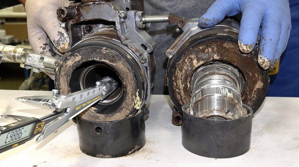
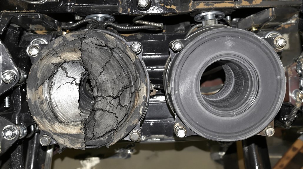
You must consult the EMD service manual and parts catalog to verify the correct bushing specifications for your specific locomotive model before initiating replacement procedures. Conduct a systematic visual inspection to identify wear indicators including surface scoring, dimensional changes, cracking, or material degradation that signal bushing failure. Document all findings with measurements and photographs to establish a baseline for comparing post-replacement conditions and validating the integrity of new components. Ensure that regular inspection schedules are maintained for all traction motor suspension components to prevent unexpected failures and optimize locomotive performance.
Bushing Specification Document References
Before initiating any bushing replacement procedure, verify that you’re working with the correct component specifications by consulting document reference 40036366 for traction rod bushings or document reference 40076633 for motor nose link bushings. These documents establish material traceability requirements and provide essential working load capacity data, including the critical 9300 Kg-cm specification for traction rod applications.
Cross-reference the EMD Locomotive Specification Book SW1001-SPEC8070-03JAN72 for thorough truck assembly integration details. Make certain all components meet A.A.R. material specifications for axle physical properties. Maintain strict revision control throughout the replacement process by documenting specification version numbers and amendment dates. You’ll need this documentation to verify compatibility with EMD locomotives including WDG4, WDG4D, WDP4B, and WDP4D models. Confirm specifications before proceeding with disassembly operations.
Visual Wear Assessment Criteria
When conducting visual wear assessment on traction motor bushings, establish a systematic inspection protocol that begins with steam washing all disassembled components to expose underlying surface conditions. You’ll need to examine each bushing systematically before initiating replacement procedures.
Document critical wear indicators through thorough evaluation:
- Examine wear patterns on bushing surfaces to identify alignment irregularities or uneven load distribution affecting component performance
- Conduct thermal imaging to detect temperature rises of 10-20°F above baseline readings indicating degradation
- Perform lubrication analysis to assess contamination levels and adequacy for high-temperature, heavy-load operations
- Record vibration signatures in the 25-100 kHz range to establish baseline measurements for future monitoring
- Inspect for surface irregularities including frettings, flutings, and frostings that indicate specific damage pattern types
These documented findings establish failure timelines and justify replacement decisions based on quantifiable deterioration indicators.
Integrity Evaluation Methods
Thorough integrity evaluation begins with electrical testing protocols that verify motor winding conditions and isolate potential failure points. You’ll conduct insulation resistance testing to assess winding integrity, followed by hipot testing to identify breakdown risks. Electrical diagnostics include voltage monitoring (600-750V range) and current assessment up to 1200A to prevent component overstressing.
Vibration monitoring detects mechanical anomalies indicating bearing wear or misalignment issues. You’ll analyze frequency domain signatures to pinpoint specific deterioration patterns before catastrophic failure occurs. Conduct visual inspections of brushes, commutators, and bearings to identify wear patterns and component degradation early.
| Evaluation Method | Critical Parameters |
|---|---|
| Insulation Resistance | Winding condition verification |
| Voltage Monitoring | 600-750V operational range |
| Current Assessment | Maximum 1200A threshold |
| Vibration Analysis | Bearing failure detection |
| Load Distribution | Alignment verification |
Document all measurements for compliance and trend analysis purposes.
Bogie Assembly Removal and Bushing Access Methods
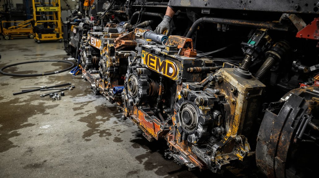
To access traction motor bushings for replacement, you must first remove the entire bogie assembly from the locomotive superstructure. This process requires systematic disconnection of all physical connections, including traction motor cables, brake gear attachments, and car body traction rods at the bogie end. Once you’ve raised the superstructure equally at all four corners using high lift jacks, you can disengage the body swivel castings from the bogie swivel bowl and run the bogie assembly out along the track. Heavy-duty chain connected between the high lift equipment and the locomotive provides controlled movement during positioning operations.
Complete Bogie Removal Process
Before attempting complete bogie removal from an EMD locomotive, you must systematically disconnect all physical, electrical, and pneumatic connections linking the superstructure to the bogie assembly. This includes isolating traction motor electrical connections, disconnecting brake lines with proper capping, and securing all auxiliary sensors and control cables. Your facility’s rigging plan should prioritize drop pit arrangements, which markedly reduce component removal requirements and minimize downtime.
Essential Bogie Removal Steps:
- Position high lift jacks at all four corners, raising the superstructure equally to prevent underframe strain
- Disconnect and restrain traction motor connections away from the removal path
- Avoid lifting one end excessively until body swivel castings disengage from the bogie swivel bowl
- Run the disconnected bogie out along the track using appropriate wheel set trolley equipment
Component Access Procedures
Although complete bogie removal provides unrestricted access to suspension components, you can replace traction motor bushings through targeted access methods that keep the bogie assembly in place. These access techniques require proper locomotive jacking and support procedures to create clearance between the traction motor and truck frame. You’ll need to establish stable support points following safety protocols that prevent unexpected movement during component manipulation.
Before accessing bushings, verify all electrical connections are isolated and motor pinion engagement is released. Position hydraulic jacks at designated lifting points on the locomotive frame, ensuring load distribution prevents frame distortion. Once you’ve created adequate clearance, you can remove suspension retaining hardware and extract worn bushings using specialized pulling tools. Maintain continuous monitoring of jack stability throughout the procedure to prevent catastrophic equipment failure. Document and label all disassembled parts to ensure proper reassembly sequence and correct orientation of components.
Traction Rod Bushing Removal and Installation Steps
Once you’ve completed lockout/tagout procedures and positioned your lifting equipment, you’ll begin the bushing replacement process by pulling back the dog bone assembly using a sling and come-along to create adequate clearance for traction motor access. Ratchet the dog bone components back while positioning your lifting table’s center hydraulic cylinder beneath the motor assembly. Use a ram extension over the cylinder to prevent slippage during rotation.
Extract the rubber-to-metal bonded bushings from their positions between the bearing adaptor and bogie frame. These components endure significant load dynamics including:
- Radial forces from wheel-set guidance operations
- Torsional stresses during acceleration and braking
- Cocking mode deflections from track irregularities
- Longitudinal thrust transmission through the rod assembly
Install replacement bushings following manufacturer torque specifications precisely. Align components properly to assure effective force transmission from wheel-set to bogie frame. Choose aftermarket parts that meet OEM specifications for reliability. Release the sling mechanism, allowing the dog bone to return to operating position after verification.
Motor Nose Link Bushing Replacement Procedures
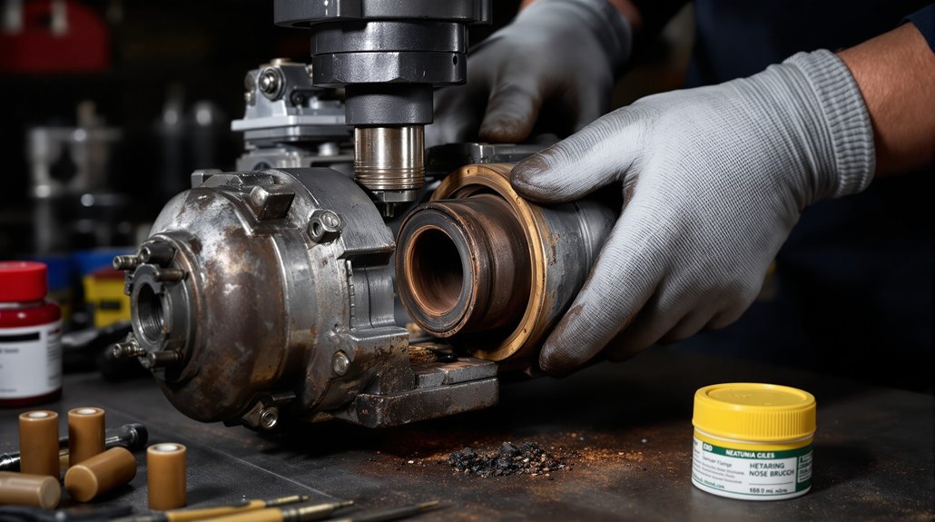
Between the traction motor suspension nose and the bogie frame transom, motor nose link bushings serve as critical load-bearing components that require methodical replacement procedures to maintain locomotive operational integrity.
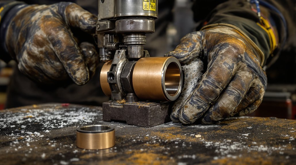
You’ll begin by implementing complete lockout/tagout procedures and establishing proper motor support. Disconnect the nose link rod from the traction motor’s lower connection point, then use specialized hydraulic pullers to extract bushings without damaging mounting surfaces. Clean all debris from mounting points before proceeding.
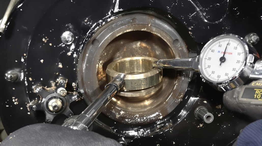
During installation, position new bushings with links rotated 4 degrees off center for proper alignment. Material sourcing must meet EMD HHP specifications for rubber-to-metal bonded components rated for radial loads up to 11,000 kg and torsional loads up to 3,190 kg-cm at 4.5°.
Verify correct angular positioning for cocking mode capacity of 7,100 kg-cm at 3°. Post-installation, conduct dynamic loading tests and vibration analysis to confirm noise reduction performance and proper cushioning function within the -10°C to 60°C operational range.
Torque Specifications and Component Securing Guidelines
Proper bushing installation requires precise torque application to maintain structural integrity and prevent premature component failure. You’ll need to follow EMD Engineering Standards specifications for all threaded fasteners in your traction motor suspension assembly. The 300M bolt specifications outlined in page 8-2.051 provide essential guidance for achieving correct thread preload values.
Apply these critical torque specifications during your installation:
- Use fastener lubrication before torquing all threaded connections to achieve accurate preload
- Apply 320 ft-lbs installation torque for 3/4-10 fasteners with maximum breakaway between 320-380 ft-lbs
- Verify 350 ft-lbs as your standard reference point for normal breakaway value calculations
- Consider Huck fasteners as optional securing method for enhanced component retention
You must verify breakaway torque falls within specified ranges after initial installation. Quick access latch-type inspection covers allow you to perform ongoing torque verification checks throughout your maintenance intervals, ensuring sustained fastener integrity.
Post-Installation Testing and Performance Verification
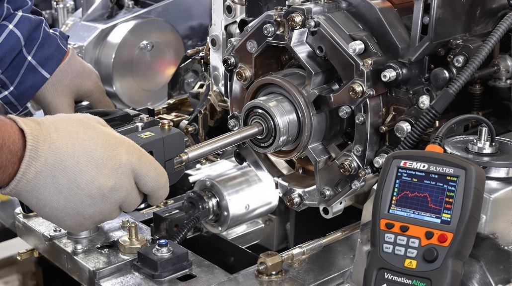
After completing bushing installation and torque verification, you’ll need to execute exhaustive testing protocols to confirm proper motor assembly integration. Vibration analysis provides non-invasive detection of motor anomalies including imbalance, misalignment, and bearing failure indicators. You’ll monitor vibration signatures to detect irregularities in load distribution and alignment issues within motor assemblies. Conduct exhaustive visual inspections alongside dimensional assessments of reassembled components.
| Testing Method | Acceptance Criteria | Sampling Rate |
|---|---|---|
| Vibration Analysis | Normal noise signatures, stable trend data | 100% of assemblies |
| Dimensional Verification | Within technical drawing tolerances | Per sampling plan |
| Ultrasonic Testing | Bond quality meets metallurgical standards | 100% coverage |
Supplement your testing with thermal imaging to identify heat anomalies indicating friction or misalignment. Performance evaluation examines locomotive characteristics under specified voltage supply conditions. You’ll reject components producing dull sounds during ringing tests, as acceptable bearings produce clear tones confirming proper material bonding integrity. Verify insulation resistance measurements on motor windings to ensure electrical integrity after reassembly procedures.
Frequently Asked Questions
What Is the Typical Service Life of Traction Motor Bushings in EMD Locomotives?
Like a relay race where the baton’s condition determines success, traction motor bushings don’t have a fixed average lifespan—you’ll find mileage variability depends heavily on operating conditions. While the documentation doesn’t specify exact intervals, you must inspect bushings during periodic maintenance cycles: every 92 days for older units, 184 days for newer microprocessor-equipped locomotives. Environmental factors, vibration wear, and temperature extremes accelerate degradation, requiring you to replace bushings when inspections reveal excessive wear or damage.
Can Bushings From Different EMD Locomotive Models Be Used Interchangeably?
You can’t automatically assume interchange compatibility between different EMD locomotive models without thorough verification. While aftermarket suppliers offer components designed to fit multiple traction motor models, you’ll need to conduct specific compatibility testing before installation. Material differences and dimensional variations exist across D77, D78, D87, D90, and D100 models. You must compare part specifications, verify load capacities, and guarantee precise dimensional matches to maintain safety and operational integrity during bushing replacement procedures.
What Are the Signs Indicating Urgent Bushing Replacement Versus Routine Maintenance?
Like warning lights on a dashboard, urgent signs demand immediate action: excessive vibration analysis readings signaling bearing collapse, thermal degradation melting seal rings from failed bearings, severe alignment wear causing catastrophic load distribution, or electrical tracking from contamination. You’ll schedule routine replacement when detecting gradual vibration trends, minor debris infiltration, uneven wear patterns, or condensate accumulation. Critical failures won’t wait—they’ll cascade into complete motor breakdown if you ignore them.
How Often Should Bushing Inspections Be Performed Under Normal Operating Conditions?
You’ll need to perform weekly checks of traction motor suspension bushings during routine maintenance cycles, monitoring for unusual noises, vibrations, and signs of wear. Additionally, conduct quarterly inspections that include lube oil analysis to detect contamination indicating potential bushing degradation. During these intervals, you should systematically examine all moving parts, check for proper lubrication, and document findings in maintenance logs to make certain compliance and track component condition over time.
Are There Approved Alternative Suppliers for EMD-Specification Replacement Bushings?
Yes, you’ll find approved aftermarket vendors like Mikura International supplying EMD-specification bushings. Think of certification as your quality compass—third party certifications verify these suppliers meet original equipment standards for radial, torsional, and cocking mode loadings. You must verify replacement components match EMD part numbers 40036366 (traction rod) and 40076633 (motor nose link) while conforming to current A.A.R. material specifications and documentation requirements.