
You’ll detect worn traction motor bushings through circumferential scoring marks, axial grooves, and surface pitting on visual inspection. Listen for squealing, grinding, or rhythmic tapping during operation. Monitor for vibration signatures at 80–120 Hz, temperature elevations exceeding 160–180°F at contact points, and voltage ripple above 5%. Measure radial play beyond 0.015 inches or axial movement exceeding 0.010 inches against manufacturer specifications. You’ll observe reduced torque output, current fluctuations approaching 1,200 amperes, and thermal gradients surpassing 15°C between bearing ends—each indicating progressive deterioration that compromises interconnected components throughout your traction system.
Key Takeaways
- Circumferential scoring marks, axial grooves, surface pitting, cracking, and compression flattening indicate physical deterioration from excessive movement and stress cycles.
- Squealing, grinding, rhythmic tapping, and crackling noises signal metal-to-metal contact and irregular component movement from worn bushings.
- Vibration signatures at 80–120 Hz during loaded operations with amplitude increases beyond baseline ~0.3 in/s indicate bushing wear.
- Bearing surface temperatures exceeding 95°C and temperature gradients greater than 15°C between bearing ends reveal friction from inadequate clearances.
- Shaft misalignment from worn bushings causes eccentric loading, gear tooth imbalance, commutator degradation, and accelerated component deterioration.
Visual Indicators of Bushing Deterioration

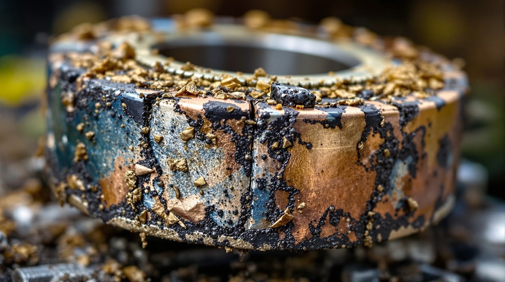
When inspecting traction motor bushings during maintenance intervals, you’ll encounter distinct wear patterns that reveal the underlying failure mechanisms. Circumferential scoring marks indicate rotational movement between the bushing and housing, while axial grooves signal excessive longitudinal displacement. Surface pitting demonstrates fatigue damage from repeated stress cycles, and visible cracking on the outer diameter suggests imminent material failure.
You’ll notice surface texture changes where the smooth factory finish becomes roughened through abrasive wear. Visual corrosion appears as water stains or rust products from seal failures and moisture ingress. Discoloration from the original material color indicates thermal degradation, with blue or purple heat tints confirming excessive operating temperatures.
Material delamination manifests as separation of bushing layers or surface flaking. Compression flattening occurs at load points, while bulging exceeds original dimensional specifications. Metal particles embedded in the surface and fretting damage marked by oxidized particles provide definitive evidence of advanced deterioration requiring immediate replacement. Inspection positions should include both drive end and non-drive end locations to ensure comprehensive bushing assessment.
Auditory Warning Signs During Motor Operation

During locomotive traction motor operation, you’ll detect specific acoustic signatures that precede catastrophic bushing failure. Squealing sounds indicate metal-to-metal contact as clearances exceed specifications, while grinding noises signal excessive shaft movement causing irregular component contact. You’ll notice rhythmic tapping from loose bushings permitting shaft oscillation and high-pitched whining from increased friction under load conditions.
Crackling or popping noises reveal electrical arcing caused by misaligned components due to shaft displacement. Buzzing intensifies when connections destabilize from vibration, and sharp snapping occurs during irregular brush contact patterns. Low-frequency rumbling increases with shaft eccentricity, while harmonic resonance develops from loose component frequencies interacting with rotation speeds.
Operator feedback proves critical when identifying alternating pitch variations indicating speed irregularities and surging sounds from binding misaligned components. Acoustic diagnostics enable early detection of pulsating patterns from eccentric shaft rotation and cyclic groaning from inconsistent load paths through deteriorated bushings. Systematic troubleshooting of abnormal sounds involves listening for sounds and correlating them with specific motor operating conditions to pinpoint failing bushings.
Performance Degradation and Efficiency Loss
As bushing wear progresses beyond acceptable tolerances, you’ll measure quantifiable performance losses through vibration amplitude increases and thermal efficiency reductions. RMS signal envelope measurements across 0-200Hz, 0-1kHz, and 0-5kHz frequency bands reveal deteriorating conditions, with 8,096 data points documenting decline patterns. You’ll observe reduced torque output as misaligned bushings cause pitting and scoring on pinion gear teeth, preventing proper meshing.
Energy leakage occurs through increased friction and heat generation from inadequate lubrication, forcing cooling systems to work harder while efficiency drops. Voltage ripple exceeding 5% indicates bearing-related electrical issues, with current fluctuations up to 1200A affecting motor performance. Temperature monitoring reveals overheating patterns from excessive bushing friction, while electrical erosion damages components and reduces overall efficiency. Analyzing these wear patterns against benchmarks enables early detection of bushing degradation before severe damage compromises traction motor reliability. Carpet level envelope spectrum analysis detects degradation even in high-noise environments, enabling you to identify performance decline before catastrophic failure occurs.
Electrical System Irregularities
You’ll detect electrical system irregularities through measurable increases in circuit resistance as worn bushings create poor contact surfaces and contaminated connections. Your monitoring systems will record current asymmetry between traction motors, with faulty units showing markedly lower armature current readings that trigger repeated fault conditions. Voltage anomalies manifest through multimeter testing, revealing interruptions in electrical flow pathways and resistance level deviations that exceed manufacturer specifications. Worn bushings can lead to blown fuses as degraded electrical connections create resistance spikes that exceed circuit protection thresholds.
Increased Resistance and Faults
When traction motor bushings deteriorate, they trigger a cascade of electrical resistance issues that compromise locomotive performance and safety. You’ll observe increased resistance at failure points, particularly where corroded ferrules create high-resistance connections generating excessive heat. Mechanical damage compromises conductors internally, reducing copper cross-section and elevating current density. This deterioration produces arcing hotspots that progressively melt insulation and create ground fault conditions.
| Resistance Indicator | Critical Threshold |
|---|---|
| Voltage ripple levels | >5% abnormal |
| Current approach to rating | 1200A maximum |
| Combined system losses | 16-17% typical |
| Operating voltage range | 600-750V normal |
Monitor temperature anomalies, measure resistance across suspected connections, and track efficiency degradation patterns. These measurements reveal developing faults before catastrophic failures occur, enabling preventive maintenance interventions. Loose clamps allow cables to experience excessive cable motion that breaks strands inside the conductor over time.
Current and Voltage Anomalies
Traction motor bushings in deteriorated condition produce measurable electrical anomalies that manifest as voltage instabilities and current imbalances throughout the propulsion system. You’ll observe voltage transients outside the standard 600-750 V operating range, indicating compromised electrical pathways. Current flow deviations from the nominal 1200 A threshold signal degraded connection integrity within motor assemblies. Phase imbalance between motor circuits reveals internal component deterioration requiring immediate attention.
Voltage ripple exceeding 5% produces harmonic distortion that accelerates motor damage. Your monitoring systems will detect ground-fault conditions as worn bushings create unintended electrical paths to chassis ground. Precision instrumentation identifies these anomalies through continuous voltage and current tracking, enabling data-driven maintenance decisions. Connection resistance increases progressively as bushing materials degrade, compromising proper grounding and electrical distribution. Real-time monitoring systems enable immediate corrective actions when electrical irregularities are detected.
Measurement Deviations During Routine Maintenance
During routine maintenance intervals, you’ll measure bushing clearances against manufacturer specifications, typically finding tolerances exceeded when radial play surpasses 0.015 inches or axial movement exceeds 0.010 inches. Your handheld vibration monitoring systems will detect amplitude increases beyond baseline readings of 0.3 inches per second, correlating directly with bearing surface degradation. You’ll observe temperature elevations exceeding normal operating ranges of 160-180°F at bushing contact points, indicating friction from inadequate clearance maintenance.
Bushing Clearance Tolerance Exceedance
As routine maintenance intervals approach, technicians must verify that bushing clearances remain within manufacturer-specified tolerance bands to prevent bearing assembly failures. You’ll need to evaluate four extreme tolerance combinations when measuring shaft-to-bushing interfaces, accounting for manufacturing variability that creates potential clearance-to-interference variations. Components designed for interference fits may develop clearances due to tolerance accumulation and shaft corrosion effects.
Your measurements should identify whether outer races maintain proper fits with bearing brackets, preventing rotational movement during operation. When clearance fits develop within tolerance ranges, you’ll observe bearing rotation in end frames and inner race creeping. These symptoms indicate insufficient interference maintenance. Calculate extreme dimensional combinations to reveal clearance development, ensuring continuous interference fits prevent slippage and heat generation from sliding friction. Dimensional tolerances are specified in units of micrometers, requiring precision measurement equipment to detect deviations that indicate progressive wear in locomotive traction motor assemblies.
Vibration and Temperature Analysis
Beyond dimensional inspection protocols, measurement deviations in vibration and temperature parameters provide quantitative indicators of bushing deterioration during scheduled maintenance intervals. You’ll observe elevated bearing body temperatures correlating directly with increased vibration impact levels when bushings exceed clearance tolerances. Acoustic monitoring detects surface waviness-induced abnormalities that accelerate fatigue progression in motor bearing races. During routine checks, you must account for operational frequency-dependent heating patterns, as DC-link voltage pulsation at 100 Hz generates thermal elevation in motor hangers.
Temperature readings vary markedly across different vibration conditions, providing diagnostic correlation between bearing failure advancement and amplitude variations. Lubrication effects further influence thermal measurements, requiring standardized assessment protocols that distinguish between normal operational heating and bushing wear-related temperature anomalies during maintenance documentation procedures. Measurement equipment calibration certificates must remain current and traceable to ensure accurate baseline comparisons during successive inspection intervals.
Impact on Adjacent Traction Motor Components
Worn traction motor bushings initiate a cascade of mechanical failures throughout the motor assembly, with armature shaft misalignment representing the most immediate consequence. This misalignment generates eccentric loading patterns that accelerate deterioration across interconnected components.
Deteriorating bushings trigger armature misalignment, creating eccentric loads that systematically compromise adjacent motor components through accelerated mechanical stress propagation.
Progressive Component Damage Sequence:
- Bearing Contamination – Excessive bushing clearances allow metallic particles and moisture ingress into bearing assemblies, compromising lubrication integrity and reducing bearing service life by 40-60%.
- Commutator Surface Degradation – Shaft misalignment causes uneven brush pressure distribution, creating localized heating zones and accelerated copper wear patterns.
- Field Coil Insulation Stress – Increased vibration amplitudes from unstable rotor positioning generate repetitive mechanical stress on field winding insulation, risking thermal breakdown.
- Gear Tooth Loading Imbalance – Axial and radial shaft displacement transfers abnormal forces to pinion-gear interfaces, inducing premature tooth pitting and spalling failures. Surface waviness on bearing races compounds these effects by introducing additional vibration frequencies that destabilize the entire traction power transmission system.
Monitor clearance specifications during scheduled inspections to prevent component degradation propagation.
Vibration and Alignment Issues
When traction motor bushings exceed their wear limits, characteristic vibration signatures emerge at frequencies between 80-120 Hz during loaded operations, with peak amplitudes occurring at approximately 100 Hz. You’ll observe shaft harmonics that deviate from baseline patterns as worn bushings allow excessive motor movement, disrupting optimal worm gear meshing geometry.
Misalignment develops when bushings can’t maintain mounting tolerances, creating uneven load distribution across support structures. Your vibration analysis will detect frequency bandwidth expansion and modal behavior shifts as bushing stiffness decreases, altering the assembly’s natural frequency characteristics. Monitoring vibration data trends over time enables detection of sudden changes that may indicate progressive bushing deterioration before complete failure occurs.
| Vibration Indicator | Degradation Evidence |
|---|---|
| Amplitude increases | Exceeds normal operational baselines in specific frequency ranges |
| Harmonic content changes | Detectable shifts in shaft harmonics and resonance patterns |
| Alignment deviations | Motor positioning changes affecting geometric relationships |
Resonance conditions intensify when meshing frequencies approach the system’s altered natural frequencies, while mechanical looseness generates broader frequency spectra that signal imminent component failure.
Temperature and Thermal Anomalies
Thermal anomalies in traction motor bushings manifest through measurable temperature deviations that exceed the standard 70°C-90°C operating range, signaling friction-induced wear and impending failure. You’ll detect these critical indicators through thermal mapping procedures that reveal localized hot spots at bearing interfaces where degraded bushings create excessive friction.
Critical thermal indicators include:
- Bearing surface temperatures exceeding 95°C during normal load conditions, indicating insufficient clearance from bushing wear
- Temperature gradients above 15°C between bearing ends, revealing uneven bushing deterioration patterns
- Rapid temperature spikes during acceleration cycles that suggest metal-to-metal contact from bushing material loss
- Persistent elevated readings despite coolant optimization adjustments, confirming mechanical degradation rather than thermal management issues
You must implement infrared scanning during maintenance intervals to identify developing problems. Thermal imaging technology enables non-contact measurement across motor assemblies, detecting anomalies before catastrophic failure occurs. Temperature monitoring provides quantifiable data for predictive maintenance decision-making.
Frequently Asked Questions
What Is the Typical Lifespan of Locomotive Traction Motor Bushings?
Your locomotive traction motor bushings typically last 10,000+ hours under normal operating conditions, though this varies based on maintenance practices and operational demands. You’ll need to monitor electrical insulation integrity and material hardness degradation throughout service life. Regular lubrication intervals every 92-184 days extend bushing longevity, while inadequate maintenance accelerates wear. You should replace bushings when experiencing unusual vibration, temperature increases, or visible shaft grooving, as these indicate compromised performance standards.
Can Worn Bushings Be Repaired or Must They Always Be Replaced?
When bushings wear beyond specification limits, you’ll face a critical junction. Your repair options include resurfacing bearing surfaces and reconditioning if damage remains within manufacturer tolerances. However, replacement criteria dictate complete substitution when wear exceeds acceptable parameters or cracks appear. You can’t restore severely deteriorated bushings to original specifications—they’ll compromise motor performance and reliability. Cost analysis between repair procedures and genuine replacement parts from authorized suppliers determines your best maintenance approach.
How Much Does Replacement of Traction Motor Bushings Typically Cost?
You’ll find traction motor bushing replacement costs vary markedly based on locomotive type and repair facility. Labor costs typically range from $500-2,000 per motor, depending on accessibility and whether you’re removing the entire motor for bench work. Parts sourcing affects pricing substantially—OEM bushings cost $50-300 each, while bronze or composite aftermarket options may reduce expenses. You’ll need to factor in potential armature machining if wear’s excessive.
What Preventive Maintenance Practices Extend Bushing Service Life Most Effectively?
You’ll extend bushing service life most effectively through regular lubrication using manufacturer-specified products applied at 184-day intervals. Implement vibration monitoring systems to detect early wear patterns before failure occurs. You should maintain strict cleanliness protocols, removing metallic debris and contaminants during scheduled inspections. Combine thermal imaging with ultrasonic testing to identify developing issues. This integrated approach can reduce maintenance costs by 15% while improving asset availability by 25%.
Are Certain Locomotive Models More Prone to Bushing Wear Than Others?
You’ll find older models with axle-hung designs demonstrate higher bushing wear rates due to direct exposure to track irregularities and unsprung mass dynamics. These configurations transmit full track forces through motor bushings, accelerating degradation. Nose-suspended motors experience 40-60% more bushing stress compared to frame-mounted designs. GE D77 and EMD D87 series motors, common in first-generation diesels, require more frequent bushing replacement than modern AC traction systems with improved isolation characteristics.