
Understanding the Critical Challenge: Your Grid Box Testing Struggles
Locomotive maintenance professionals face enormous challenges when attempting to execute comprehensive electrical system diagnostics. The grid box (load box) represents perhaps the most complex testing apparatus in locomotive maintenance, requiring seamless integration with multiple electrical systems simultaneously. Many technicians struggle to comprehend how this critical testing device communicates and coordinates with generators, excitation control systems, voltage regulators, and protective relay networks. Without proper understanding of these interactions, load box testing becomes unreliable, producing inaccurate measurements and compromising locomotive performance validation. This knowledge gap directly impacts your ability to diagnose problems accurately and execute maintenance efficiently.
Key Problems You’re Likely Experiencing:
- Unclear voltage stability during load box resistance changes and throttle adjustments
- Inconsistent electrical measurements across different test conditions and configurations
- Accidental activation of protective relays causing test procedure interruptions
- Thermal management challenges when operating at maximum load box capacity
- Difficulty interpreting transient responses from excitation control systems
- Generator output fluctuations that seem unpredictable or uncontrollable
- Lack of standardized procedures for different locomotive manufacturers (EMD, ALCO, GE)
- Insufficient guidance on safe current levels and voltage regulation thresholds
The Fundamental Role of Grid Box in Locomotive Electrical Architecture
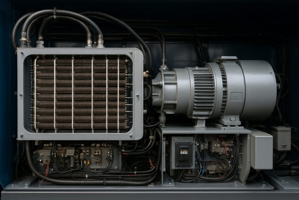
The grid box functions as the locomotive’s primary static testing apparatus. It simulates traction motor loads without requiring actual rail connection. During testing, the grid box converts electrical generator output into measurable heat energy. This conversion enables technicians to verify locomotive horsepower delivery safely. The grid box essentially becomes a controlled environment for comprehensive electrical system validation.
Modern locomotives employ grid boxes constructed from nichrome wire resistance elements. These elements can withstand extreme temperatures exceeding 400 degrees Celsius. The apparatus dissipates several megawatts of power during full-load testing. Forced-air cooling systems manage the resulting thermal stress. The entire system operates under precise microprocessor control in contemporary locomotives.
Why Grid Box Integration Matters
The grid box cannot operate independently from other electrical components. Every adjustment in resistance configuration creates electrical transients throughout the system. The main generator responds to these transients through its inherent impedance characteristics. Voltage regulators must compensate rapidly for any output fluctuations. Protective relays must remain dormant during testing procedures. Battery charging systems must continue functioning during load box operation.
Table 1: Grid Box Testing Parameters and Safe Operating Ranges
| Parameter | Typical Range | Maximum Safe Level | Critical Monitor Point |
|---|---|---|---|
| Load Box Current | 0-3000 Amps | 3500 Amps | Overcurrent relay sensitivity |
| Generator Output Voltage | 600-900 Volts DC | 950 Volts | Voltage regulator trip point |
| Coolant Temperature | 65-95°C | 105°C | Cooling system bypass activation |
| Engine Speed During Test | Idle-1800 RPM | 1800 RPM | Governor full-speed setting |
| Thermal Management Capacity | 1-5 MW | 6+ MW | Heat exchanger maximum capability |
The Generator-Grid Box Relationship: Power Delivery Foundation
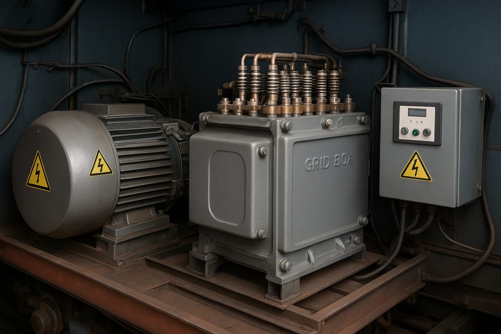
The main generator represents the electricity source for the entire grid box testing procedure. Generator performance fundamentally determines whether accurate electrical measurements can be obtained. The generator produces electrical output through rotating magnetic field principles. Engine mechanical power drives the generator’s rotor in diesel-electric locomotives.
The generator’s drooping voltage characteristic creates interesting dynamics. As load box current increases, generator output voltage naturally decreases slightly. This phenomenon occurs due to resistive voltage drops within generator windings. Modern excitation systems compensate for this drooping through sophisticated control algorithms. Voltage regulation becomes increasingly important as load box resistance decreases.
Generator Output Control During Testing
The excitation control system manages generator field current precisely. Field current directly determines magnetic flux density within the generator. Flux density proportionally affects generator output voltage. The control system receives continuous feedback regarding actual generator voltage. Microprocessor algorithms calculate required field current adjustments hundreds of times per second.
When load box resistance suddenly changes, the generator faces an instantaneous load transient. The engine governor must increase fuel delivery to maintain speed. The excitation system must simultaneously adjust field current to regain proper voltage. This coordinated response must occur within milliseconds to prevent measurement errors.
Table 2: Excitation System Response Times and Accuracy Requirements
| Response Type | Typical Response Time | Accuracy Requirement | System Component |
|---|---|---|---|
| Voltage correction to load transient | 50-100 milliseconds | ±2% of setpoint | Voltage regulator |
| Field current adjustment | 30-80 milliseconds | ±3% | Exciter circuit |
| Engine governor fuel adjustment | 200-400 milliseconds | ±50 RPM | Governor actuator |
| Protective relay suppression signal | 10-20 milliseconds | Instantaneous | Control computer |
| Thermal management fan response | 1-2 seconds | Operating parameter | Cooling system logic |
Voltage Regulation: The Critical Synchronization Point
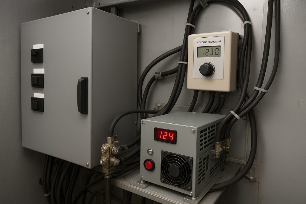
Voltage regulators manage electrical stability throughout load box testing. These sophisticated devices continuously monitor actual generator output voltage. Comparison circuits measure actual voltage against stored reference values. Deviation detection triggers corrective field current adjustments automatically.
The closed-loop control architecture ensures remarkable voltage stability. During traditional manual testing, voltage fluctuations exceeded ±5% regularly. Modern microprocessor-controlled systems maintain voltage within ±1% consistently. This improvement dramatically enhances electrical measurement accuracy and diagnostic reliability.
Voltage Regulator Challenges During Load Box Operation
When load box resistance changes rapidly, voltage transients occur inevitably. The regulator must suppress these transients while maintaining stability. Proportional-integrative-derivative algorithms manage the compensation process mathematically. Excessive compensation could cause voltage oscillations or hunting behavior. Insufficient compensation leaves unacceptable measurement errors in the recorded data.
Load boxes presenting constant-resistance characteristics pose particular challenges. Actual traction motors display variable impedance based on speed and torque. The constant-resistance load box creates more severe, abrupt transients. Voltage regulators must employ sophisticated anticipatory algorithms for optimal performance.
Protective Relay Network Coordination: Safety During Testing
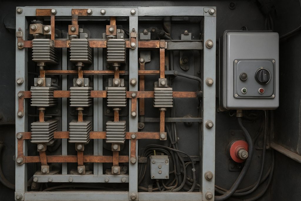
Protective relays safeguard locomotive electrical systems from abnormal operating conditions. These critical safety devices monitor overcurrent, ground faults, and thermal conditions. Load box testing procedures must prevent unwanted protective relay activation. False trips interrupt testing sequences and compromise diagnostic procedures.
Overcurrent Relay Interaction With Grid Box Testing
Overcurrent relays continuously monitor main generator current output. These relays feature adjustable sensitivity thresholds. During load box testing, generator current approaches or exceeds maximum sustainable values. The control system must either adjust protective relay thresholds temporarily or confirm they remain inoperative through dedicated testing mode activation.
Modern locomotives incorporate load-box-aware control systems. These systems automatically adjust protective relay sensitivities during designated testing procedures. When testing mode deactivates, normal protective settings restore instantly. This automatic coordination prevents dangerous testing situations while maintaining full protection during revenue service.
Ground Fault Detection Coordination
Ground fault relay systems detect unintended electrical paths to locomotive ground structure. These relays employ sophisticated signal analysis to distinguish legitimate signals from fault conditions. High-current load box operation could potentially generate false alarm signals. Proper load box circuit design ensures isolated return paths preventing ground current confusion.
Table 3: Common Protective Relay Issues During Load Box Testing
| Relay Type | Common False Trip Trigger | Prevention Strategy | Safety Impact |
|---|---|---|---|
| Overcurrent | Exceeding sensitivity threshold | Adjust threshold or activate test mode | None if test mode engaged |
| Ground Fault | False signal interpretation | Isolated return path design | Critical safety risk |
| Thermal Overload | Extended test duration | Monitor timing and activate cooling | Engine protection required |
| Generator Overvoltage | Excitation system lag | Voltage regulator tuning | Equipment damage risk |
| Motor Field Protection | Transition function activation | Inhibit during test mode | Traction system risk |
Practical Tips for Successful Load Box Testing Integration
Tip #1: Pre-Test System Verification Verify that all electrical connections remain secure before initiating testing sequences. Loose connections create resistance anomalies affecting measurement accuracy. Check protective relay sensitivity settings align with established testing parameters. Confirm microprocessor control system operates in designated load box test mode automatically.
Tip #2: Throttle Command Consistency Gradually adjust engine throttle when changing load box configurations. Rapid throttle changes create severe electrical transients. The excitation control system requires time to establish new equilibrium conditions. Stable generator output ensures accurate electrical measurements throughout the test sequence.
Tip #3: Temperature Monitoring During Extended Testing Track cooling system outlet temperatures continuously during full-power testing. Thermal management capacity limits sustainable continuous power dissipation. Most load box systems can maintain full capacity for 20-30 minute periods safely. Extended testing beyond these intervals requires intermediate cooling periods.
Tip #4: Load Box Resistance Configuration Planning Sequence resistance configurations logically from highest to lowest values. This progression minimizes electrical transients and stabilizes control systems systematically. Recording electrical parameters at each stable resistance point provides comprehensive performance baseline data. Comparative analysis between resistance points identifies anomalies indicating developing problems.
Tip #5: Battery Charging System Continuity Maintain auxiliary power supply continuity throughout extended load box procedures. Battery charging systems must remain operational despite massive power draw through the load box. Auxiliary converter losses become noticeable during extended testing. Ensure adequate fan cooling of auxiliary power conversion equipment.
Expert Insight: EMD, ALCO, and GE Coordination Differences
Different locomotive manufacturers implement slightly different electrical architectures. EMD systems typically feature split cooling loops for engine and aftercooler functions. ALCO designs often employ combined cooling systems with parallel feedback paths. GE locomotives incorporate sophisticated digital governor systems with enhanced generator control.
These architectural differences require adapted load box testing procedures. Testing sequences must account for manufacturer-specific generator field response characteristics. Voltage regulation thresholds vary between manufacturers by 2-3% typically. Protective relay sensitivity settings require manufacturer-specific calibration values. Professional technicians maintain archived reference manuals for each locomotive type encountered.
Table 4: Manufacturer-Specific Load Box Testing Parameters
| Manufacturer | Generator Type | Typical Rated Output | Excitation System | Test Mode Implementation |
|---|---|---|---|---|
| EMD (Electro-Motive Diesel) | DC Generator | 800-1000 Watts | Separate exciter generator | Dedicated microprocessor mode |
| ALCO (American Locomotive) | DC Generator | 750-900 Watts | Rotating exciter | Manual threshold adjustment |
| GE (General Electric) | AC Alternator + Rectifier | 1000-1200 Watts | Electronic exciter | Automatic digital mode selection |
Thermal Management System Integration
Load box cooling systems must dissipate enormous power quantities continuously. Nichrome resistance elements reach extreme temperatures during full-power testing. Coolant circulates through the resistance grid removing absorbed heat energy. External heat exchangers transfer coolant thermal energy to ambient air.
The interaction between load box cooling and engine cooling creates interesting dynamics. Both systems compete for available cooling capacity from common radiator systems. Advanced locomotives employ separate cooling circuits allowing independent management. Older locomotives require careful flow balance between competing cooling demands.
Temperature Monitoring Best Practices
Install thermometers at both load box inlet and outlet positions. Temperature differential indicates actual power dissipation occurring through the resistance elements. Radiator outlet temperature monitoring reveals overall system thermal capacity status. Excessive temperatures require reduced load box current or extended cooling periods.
Conclusion: Mastering Grid Box Electrical Interactions
Successful locomotive electrical system diagnostics depends entirely on comprehensive grid box understanding. The load box represents far more than a passive resistance network—it functions as a sophisticated testing system requiring careful synchronization with multiple electrical subsystems. Generator coordination, voltage regulation stability, protective relay management, and thermal system performance all demand expert attention.
Professional locomotive maintenance demands expertise in these complex interactions. Understanding how excitation systems respond to load transients prevents measurement errors. Recognizing protective relay coordination requirements ensures safe testing procedures. Acknowledging thermal management limitations prevents equipment damage from extended testing.
For decades, Mikura International has partnered with locomotive maintenance facilities providing critical generator components, excitation system parts, and protective relay assemblies. Our engineering team understands these electrical interactions intimately. We supply OEM-equivalent components maintaining precise performance specifications for EMD, ALCO, and GE locomotives. When load box testing reveals generator problems or excitation system anomalies, our inventory stocks solutions for immediate deployment.
Whether you need replacement generator components, excitation system assemblies, or protective relay modules, Mikura International maintains comprehensive inventory availability. Our technical team provides application-specific guidance ensuring compatible component selection. Contact our specialists to discuss your locomotive electrical system requirements and discover how proper parts sourcing prevents future diagnostic challenges.
Master these electrical interactions, implement systematic testing procedures, and maintain equipment through trusted supplier partnerships. Your locomotive fleet will reward you with improved reliability and extended service life.