
The soak back pump is critical for locomotive turbocharger longevity by preventing oil coking, which causes over 90% of turbocharger failures. It works by circulating oil for up to 35 minutes after engine shutdown to cool bearings, maintaining proper lubrication and dissipating residual heat. Key maintenance includes monthly oil flow checks, filter replacement every 30,000-60,000 miles, and regular oil analysis. Performance benefits include extended turbocharger life by 50-100%, significant maintenance cost savings, and reduced downtime.
1. The Critical Role of Soak Back Pumps in Turbocharger Longevity
Locomotive turbocharger failures represent one of the most significant maintenance challenges in heavy-duty diesel operations. A significant proportion of these failures are directly linked to lubrication oil problems, including contamination, starvation, and thermal breakdown. These issues lead to costly repairs, operational downtime, and reduced engine reliability. The primary technical challenge addressed by the soak back pump is the phenomenon of heat soak back-the rapid temperature increase in turbocharger bearings immediately after engine shutdown, which can cause residual oil to coke and solidify, leading to bearing seizure and shaft failure.
1.1 The Oil Coking Crisis: Temperature Thresholds and Bearing Damage
Oil coking is a critical failure mode where lubricating oil, exposed to intense residual heat, thermally degrades and forms solid carbon deposits on bearing surfaces and oil passages. This process compromises lubrication and can cause catastrophic failure. Experimental data reveals specific temperature thresholds that define this risk.
- Onset of Coking: In used engine oil, the formation of coke deposits can begin at temperatures as low as 150°C.
- Post-Shutdown Temperature Rise: When an engine is switched off after running under load, the temperature of the turbocharger bearing housing can climb 25°C higher than its temperature at the moment of shutdown.
- Peak Temperatures: Under high-load conditions without active cooling, bearing housing temperatures can reach 175°C, far exceeding the coking threshold for many oils.
This thermal dynamic creates a vicious cycle: as oil cokes, it restricts oil flow and increases friction, which generates more heat and accelerates further coking.
1.2 The Dominance of Oil-Related Failures
Industry analysis consistently identifies issues with the lubricating oil system as the leading cause of turbocharger malfunctions. Problems range from the oil’s physical and chemical properties to delivery system failures. Common failure pathways include:
- Oil Starvation: Caused by blocked feed lines, pump failures, or insufficient oil pressure, leading to immediate bearing wear and seizure.
- Oil Contamination: The presence of dirt, carbon particles, or degraded oil additives accelerates wear and can clog critical oil passages.
- Oil Breakdown and Coking: As detailed above, this is a direct consequence of inadequate post-shutdown cooling and is a primary target of soak back pump operation.
These failure modes underscore that turbocharger longevity is less about the turbocharger itself and more about the integrity and management of its lubrication system.
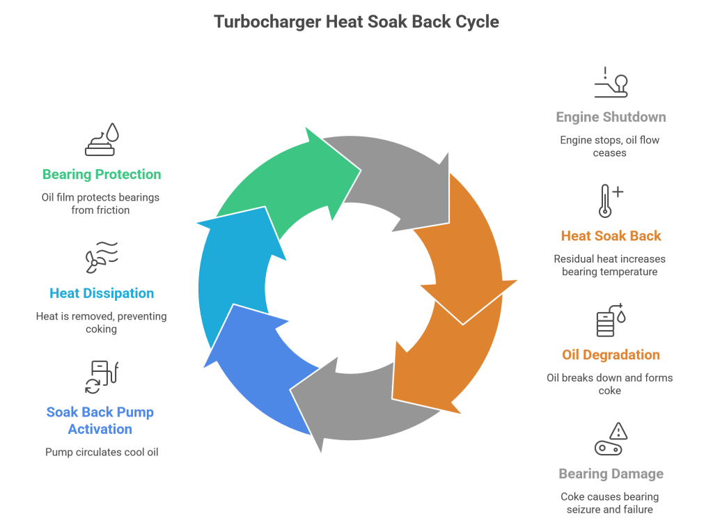
1.3 The Heat Soak Back Phenomenon: A Technical Breakdown
Heat soak back is the process where residual thermal energy from the hot turbine housing and wheel conducts radially inward through the central bearing housing after oil flow from the main engine pump ceases. This energy has no effective heat sink without continued oil circulation, causing bearing temperatures to spike. The consequences are severe:
- The thin oil film on precision bearings evaporates or chemically breaks down.
- Metallic contact increases, causing friction, micro-welding, and accelerated wear.
- Oil trapped in the hot housing begins to cook, forming hard carbon deposits that abrade surfaces and eventually block oil passages entirely.
This process is not gradual; it occurs within the first few critical minutes after shutdown, making immediate intervention essential.
1.4 The Soak Back Pump as an Engineering Solution
The soak back pump is engineered specifically to interrupt this failure sequence. It is an electrically driven auxiliary oil pump that activates automatically upon engine shutdown. Its core function is to continue circulating cool, fresh oil through the turbocharger bearings for a controlled period, typically up to 35 minutes as managed by the Locomotive Control Computer (LCC). This active cooling serves two vital purposes:
- Heat Removal: It carries away residual heat, preventing the bearing temperature from reaching the critical coking threshold.
- Bearing Protection: It maintains a protective oil film on the bearings during the turbocharger’s rotational coast-down, preventing dry friction.
Modern soak back pumps, such as those designed for Automatic Engine Start-Stop (AESS) systems, incorporate advanced features for reliability in demanding cycling applications. These include brushless induction motors to eliminate brush maintenance, liquid-cooled electronics to prevent heat-related failures, and hardened pump components for extended service life, with some designs touting maintenance-free operation for up to 10 years.
1.5 Implications for Maintenance Strategy
For experts managing locomotive and marine engine fleets, the soak back pump transforms the maintenance paradigm from reactive repair to proactive preservation. Its proper function is not optional but foundational to achieving advertised turbocharger service life. Key maintenance practices directly informed by this understanding include:
- Verifying Pump Operation: Standard procedures dictate checking oil flow through the gear train with the engine shut down and the soak back pump motor running.
- Adhering to Filter Service Intervals: The soak back filter protects the pump and turbocharger. Its replacement interval (often aligned with the turbocharger filter at 30,000-60,000 miles) is influenced by load, oil type, and operating conditions, and should not be excessively extended.
- Integrating Oil Analysis: A rigorous lube oil analysis program is strongly recommended to monitor oil condition and wear metals, providing early warning of system issues that could affect the soak back system’s effectiveness.
In conclusion, the soak back pump plays a non-negotiable role in safeguarding turbocharger investment. By directly mitigating the primary cause of oil-related failures-post-shutdown heat soak back-it is a critical component for ensuring longevity, reliability, and cost-effective operation in heavy-duty diesel applications.
2. Technical Architecture: How Soak Back Pumps Work
The soak back pump is a critical auxiliary lubrication system engineered to solve the thermal management challenges of turbocharged locomotive diesel engines. It operates independently from the main engine oil circuit to provide targeted cooling and lubrication to the turbocharger during two critical periods: immediately after engine shutdown and before engine startup.
2.1 System Components and Operational Architecture
The system consists of several integrated components:
- Pump and Motor Assembly: The core is an electrically driven pump. Standard locomotive units use a DC motor, typically rated at 3/4 HP and operating at 74 VDC input with a speed of 1200 RPM. The pump is a gear-driven design for consistent delivery. Configurations include traditional horizontal mounts (e.g., Part Number 4947308R for EMD 645 engines) and modern vertical designs with integrated AC motors and inverters.
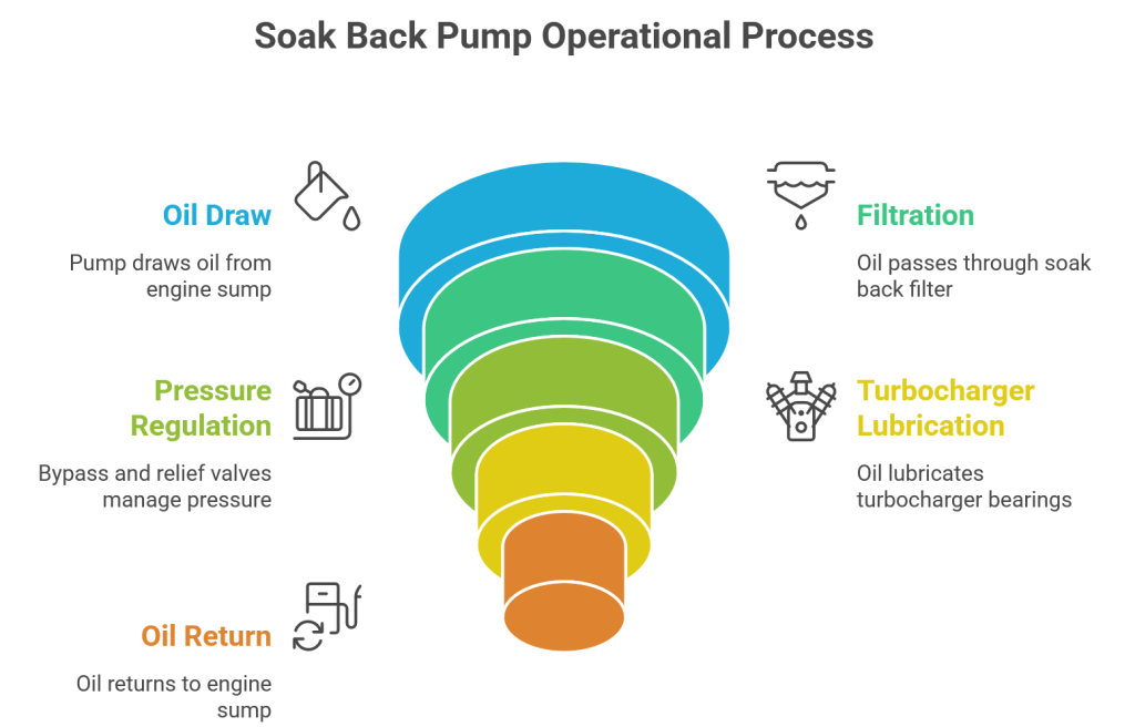
- Filtration and Pressure Regulation: Oil passes through a dedicated soak back filter. A bypass valve within the filter housing, typically set at 70 PSI, opens if the filter clogs, ensuring uninterrupted oil flow to the turbocharger. A separate relief valve in the filter head, often set at 32 PSI, returns oil to the engine sump if the turbocharger is already being lubricated by the main engine pump.
- Control and Monitoring: Operation is governed by the Locomotive Control Computer (LCC). Advanced pump designs incorporate features like brushless induction motors to eliminate brush maintenance, and liquid-cooled electronics to prevent heat-related failures.
2.2 Operational Timing and Control Logic
The LCC automates the pump with precise timing to maximize protection while conserving battery power.
- Activation Triggers: The pump runs during engine starting to pre-lubricate turbocharger bearings before cranking, and after engine shutdown to remove residual heat.
- Maximum Runtime: The LCC controls the pump motor to run for a maximum of 35 minutes during these phases. This duration is engineered to provide sufficient cooling and lubrication without excessive battery drain.
- Flow Path: When activated, the pump draws oil from the engine sump, pushes it through the soak back filter, and delivers it directly to the turbocharger before the oil returns to the sump via gravity.
2.3 Technical Specifications and Performance Parameters
Soak back pumps are built to deliver specific performance metrics crucial for protection. Common specifications derived from technical documents and procurement requirements include.
| Parameter | Typical Specification | Notes |
|---|---|---|
| Flow Rate | 13 LPM (3.5 GPM) | Other sizes (e.g., 3.0 GPM, 6 GPM) are available. |
| Differential Pressure | 2.8 bar (40 PSI) | Standard working pressure. |
| Input Voltage | 74 VDC | Common locomotive DC bus voltage. |
| Motor Power | 3/4 HP | Also available in 1/4 HP configurations. |
| Bypass Valve Setting | 70 PSI | Protects against filter blockage. |
| Relief Valve Setting | 32 PSI | Prevents over-pressurization. |
2.4 Model Variations and Engine Compatibility
Pump specifications vary to match different locomotive engine families and their operational needs.
- EMD 645 Series: Traditionally use horizontal DC pump assemblies like Part Number 4947308R.
- EMD 710 Series: Can utilize modern vertical AC pump designs, which are often compatible with both 645 and 710 V-16 engine series.
- Design Evolution: The shift from horizontal DC to vertical AC designs offers advantages like a smaller footprint (approximately 30 lbs), brushless “maintenance-free” operation, and integrated inverters. Manufacturers design these systems for extended service life, with some rated for up to 10 years of maintenance-free operation in heavy-duty applications.
2.5 System Integration and Protective Function
The pump’s integration into the broader lubrication system provides distinct protective benefits:
- Post-Shutdown Cooling: Circulating oil after the engine stops actively removes residual heat from the turbocharger’s bearings and housing, preventing the oil from coking and carbonizing on hot surfaces.
- Pre-Start Lubrication: Providing oil pressure to the turbocharger bearings before engine cranking eliminates dry-start conditions, a major source of premature bearing wear.
- Operational Reliability: The system offers a layer of redundancy. It ensures continuous oil flow during the transitions when the main engine-driven oil pump is not providing sufficient pressure.
- Support for Modern Operations: With features like brushless motors and robust construction, these pumps are specifically designed to withstand the frequent start-stop cycles of locomotives equipped with Automatic Engine Start-Stop (AESS) systems.
In summary, the soak back pump is a precisely controlled, dedicated system that directly combats the primary failure mechanisms of turbochargers in cyclic locomotive operation. Its architecture-from LCC-controlled timing to pressure-regulated filtration-is tailored to extend turbocharger life by ensuring proper lubrication during the engine’s most vulnerable operational phases.
3. Maintenance Best Practices for Soak Back Pump Systems
A systematic and disciplined maintenance regimen is paramount for the reliability of soak back pump systems and, by extension, the longevity of the turbochargers they protect. Following manufacturer-recommended procedures prevents oil starvation and heat-induced bearing failures, which are leading causes of costly turbocharger replacements. This section outlines a comprehensive maintenance strategy derived from established EMD maintenance instructions and industry practices.
3.1 Scheduled Maintenance Intervals and Operational Integration
Maintenance of the soak back system is not isolated; it must be synchronized with the engine’s overall lubrication system schedule and the turbocharger’s service cycle. The EMD scheduled maintenance program provides clear, mileage-based intervals that serve as a foundational guide.
| Interval | Primary Tasks | Key Integration Points |
|---|---|---|
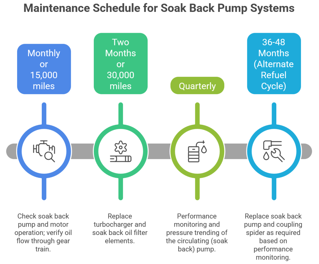
| Monthly or 15,000 miles | Check soak back pump and motor operation; verify oil flow through gear train. | Acts as a frequent health check, preceding major inspections. |
| Two Months or 30,000 miles | Replace turbocharger and soak back oil filter elements. | Aligns with the typical lower bound of turbocharger inspection cycles (30,000-60,000 miles). |
| Quarterly | Performance monitoring and pressure trending of the circulating (soak back) pump. | Correlates with recommended lube oil analysis frequency. |
| 36-48 Months (Alternate Refuel Cycle) | Replace soak back pump and coupling spider as required based on performance monitoring. | Integrated into major engine overhaul schedules. |
These intervals are influenced by several operational factors that may necessitate more frequent attention: load factor, the type and quality of lubricating oil, operational conditions (e.g., start/stop frequency), climatic conditions, and the maintenance status of the main engine lube oil filters.
3.2 Detailed Maintenance Procedures and Verification
3.2.1 Oil Flow Verification and Operational Check
This is the most critical hands-on procedure to confirm the system is functioning as designed. As detailed in EMD Maintenance Instruction MI-1740, the correct sequence is:
- Ensure the engine is completely shut down and all safety protocols, including lockout/tagout, are followed.
- Start the soak back pump motor and confirm it is running.
- Remove the left rear handhole cover to access the gear train.
- Visually check for oil flow through the gear train. The flow should be consistent and steady.
- Critical Diagnostic Step: Observe the camshaft bearings. If lubricating oil flows from these bearings while the soak back pump is running and the engine is off, it indicates a potential malfunction. The next action is to inspect the turbocharger filter outlet check valve for proper operation.
3.2.2 Filter System and Protective Valve Maintenance
The soak back filter subsystem incorporates essential pressure-protective valves that require specific checks:
- 70-PSI Bypass Valve: This valve is housed within the soak back filter assembly. Its purpose is to bypass the filter element entirely if it becomes clogged, ensuring uninterrupted oil flow to the turbocharger and preventing oil starvation. During filter changes, the housing should be inspected for proper valve seating and freedom of movement.
- 32-PSI Relief Valve: Located in the filter head, this valve’s function is to protect the system from overpressure. If the turbocharger is already receiving oil from the main engine-driven lubrication pump (e.g., during startup before the soak back pump deactivates), this valve opens at 32 PSI to return the soak back pump’s delivered oil directly back to the engine sump.
3.2.3 Motor and Pump Performance Testing
Performance verification ensures the electromechanical heart of the system meets specification. Key parameters to check include:
- Run-Time: The pump operation is typically controlled by the Locomotive Control Computer (LCC) and runs for a maximum of 35 minutes during engine starting and after shutdown.
- Output Specifications: Verify the pump delivers its rated flow and pressure. Common specifications for modern pumps are 13 LPM (3.5 GPM) at a differential pressure of 2.8 bar (40 PSI).
- Electrical & Mechanical: For traditional DC motors (e.g., 74 VDC, 3/4 HP, 1200 RPM), inspect brushes and commutators. For modern brushless induction motors, verify controller operation. In all cases, check for unusual noise, vibration, or signs of overheating.
3.3 Advanced Diagnostics and Proactive Monitoring
Moving beyond scheduled tasks, predictive maintenance techniques can identify degradation before failure.
- Pressure Trending: Systematically recording the soak back pump’s discharge pressure over time can reveal trends. A gradual pressure drop may indicate pump wear or increasing filter restriction, while erratic pressure could signal valve issues.
- Oil Analysis Integration: A rigorous lube oil analysis program is strongly recommended and forms the basis for justifying maintenance interval adjustments. Monthly or quarterly analysis of oil samples for wear metals, viscosity, and contamination provides direct insight into the health of the turbocharger bearings and the effectiveness of the filtration system, including the soak back filter.
- Control System Diagnostics: Utilizing the Locomotive Control Computer (LCC) data logs to verify the soak back pump’s commanded versus actual run times can uncover control or sensor faults.
3.4 Maintenance Checklist for Field Technicians
A concise, actionable checklist ensures no critical step is missed during service:
Pre-Work & Safety
- Engine shut down, isolated, and locked out/tagged out.
- Turbocharger confirmed cool enough to touch.
Visual & Physical Inspection
- Inspect pump, motor, and lines for leaks, corrosion, or damage.
- Check electrical connections for security and integrity.
- Verify all mounting hardware is tight.
Operational Verification
- Start soak back pump motor; confirm smooth, quiet operation.
- Remove specified handhole cover; verify oil flow through gear train.
- Check for oil at camshaft bearings (diagnostic indicator).
- Record pump discharge pressure (if gauge is available).
Filter System Service (at scheduled interval)
- Replace soak back filter element with OEM-quality part.
- Clean filter housing; inspect for debris.
- Visually inspect bypass and relief valve components.
Documentation & Follow-Up
- Record all findings, measurements, and corrective actions.
- Update unit maintenance history.
- Determine next service date based on findings and interval guidelines.
3.5 Critical Failure Prevention Insights
Analysis of maintenance data highlights key intervention points:
- Strict Filter Change Adherence: Adhering to the 2-3 month (30,000-mile) filter replacement interval is crucial. Extending beyond this risks filter structural integrity and increases the chance of the bypass valve activating due to clogging, which can allow unfiltered oil to reach the turbocharger.
- Heeding Diagnostic Clues: The procedure noting oil flow from camshaft bearings during a soak back pump test is a specific diagnostic for a failed check valve. Promptly investigating this can prevent a situation where the soak back pump cannot build sufficient pressure to lubricate the turbocharger.
- Understanding System Interaction: Recognizing that the 32-PSI relief valve is designed to work in concert with the main engine oil pressure prevents misdiagnosis of “low” soak back pressure during engine cranking, when both systems are active.
By implementing these detailed, fact-based maintenance practices, operators can transform the soak back pump from a simple auxiliary component into a cornerstone of a proactive reliability strategy, directly safeguarding turbocharger investment and operational availability.
4. Performance Benefits and Cost Savings Analysis
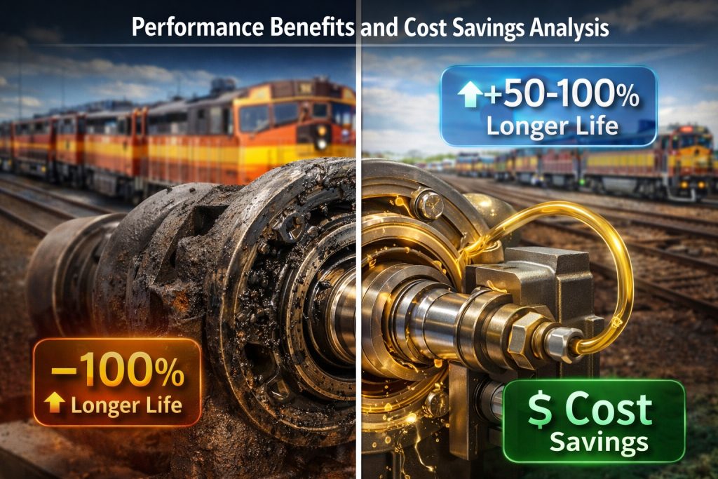
The primary value proposition of a properly maintained soak back pump system is not merely theoretical-it translates directly into measurable, quantifiable benefits for fleet operators. By addressing the root causes of premature turbocharger failure, these systems deliver substantial improvements in component longevity, reductions in maintenance expenditure, and enhanced operational reliability.
4.1 Extending Turbocharger Service Life Through Improved Lubrication
The most direct benefit is the extension of turbocharger bearing life. The system’s core function-maintaining oil flow after the main engine-driven pump stops-directly combats oil coking and starvation during the critical post-shutdown heat soak phase. Research into specialized lubrication systems, such as those incorporating hydraulic accumulators, has demonstrated that maintaining stable oil supply can improve turbocharger rotor run-out time after shutdown by 30-40%. One study focusing on individual lubrication systems showed they could double the rotor inertia duration compared to a standard engine lubrication circuit, indicating a potential halving of bearing wear rates. This data underscores the principle that extended, controlled post-shutdown lubrication directly correlates with reduced mechanical wear on high-speed bearings.
Impact of Soak Back Operation on Lubrication Duration:
| Engine Condition | Standard Lubrication System | With Functional Soak Back System | Approximate Improvement |
|---|---|---|---|
| Post-Shutdown | Oil flow ceases immediately | Oil flow continues for up to 35 minutes | Prevents dry spinning & coking |
| Pre-Start | Bearings are dry until engine oil pressure builds | Bearings are pre-lubricated before cranking | Eliminates dry-start wear |
4.2 Reducing Maintenance Costs and Downtime
The financial impact of avoiding turbocharger failures is significant. A single failure event necessitates not only the high cost of the turbocharger assembly itself but also associated labor, potential engine oil contamination, and, most critically, unscheduled locomotive downtime. Soak back pumps mitigate this risk proactively. Modern units are engineered for durability, with some designs boasting a maintenance-free service life of up to 10 years on heavy-duty equipment, eliminating the cost and downtime of regular brush replacements common in older DC motor designs.
Integrating soak back pump checks into the scheduled maintenance program is a low-effort, high-return activity. For instance, verifying operation by checking oil flow through the gear train with the engine off is a straightforward procedure that can prevent catastrophic failure. Furthermore, the system includes built-in protective features; a clogged soak back filter will bypass via a 70-PSI valve, and a 32-PSI relief valve prevents over-pressure, ensuring the turbocharger remains protected even during a filter maintenance lapse.
Comparative Maintenance Regimen:
| Task | Without Soak Back System Focus | With Soak Back System Focus |
|---|---|---|
| Turbocharger Longevity | Reliant on perfect main engine shutdown cooldown (often manual) | Protected by automated post-lubrication and cooling |
| Bearing Failure Risk | Higher risk of coking and starvation after shutdown | Significantly reduced risk due to controlled oil flow |
| System Maintenance | N/A | Quarterly operational checks and filter changes at 30,000-60,000 mile intervals |
4.3 Supporting Operational Efficiency and Modern Engine Cycles
Beyond failure prevention, soak back pumps enable more efficient locomotive operation, particularly in modern applications. They are specifically designed for compatibility with Automatic Engine Start-Stop (AESS) systems, which subject the turbocharger to frequent thermal cycles. In these demanding cycles, the soak back pump’s dual role is essential: it pre-lubricates bearings before a start and removes residual heat after a stop, making frequent start-stop operation viable without sacrificing turbocharger life.
The system’s automated operation, controlled by the Locomotive Control Computer (LCC) for a prescribed period (up to 35 minutes), also eliminates the need for manual engine idling to cool down the turbocharger, leading to direct fuel savings and reduced engine wear.
4.4 Return on Investment Considerations
The return on investment for ensuring a functional soak back pump system is compelling when viewed through the lens of total cost of ownership. The cost of a pump and its routine maintenance filters is minor compared to the expense of a turbocharger overhaul or replacement and the associated locomotive out-of-service time. The investment protects a critical, high-value component. Implementing a rigorous oil analysis program, as recommended by maintenance guides, further enhances this ROI by providing trend data on wear metals, allowing for predictive maintenance and justifying potential extensions of service intervals based on actual oil condition.
In summary, the soak back pump is a quintessential example of a modest, targeted engineering solution that delivers disproportionate economic benefits. By ensuring continuous lubrication during the turbocharger’s most vulnerable operational phases-immediately after shutdown and just before startup-it directly extends component life, reduces the frequency and severity of maintenance events, and supports the reliable, efficient operation demanded in modern locomotive service.
5. Advanced Monitoring and Diagnostic Integration
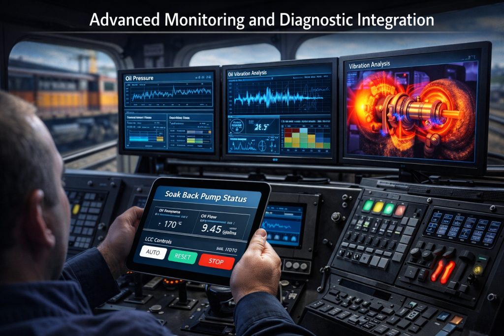
The evolution from reactive to predictive maintenance has made advanced monitoring and diagnostic integration a cornerstone of modern locomotive upkeep. For turbocharger longevity, integrating the soak back pump with sophisticated condition monitoring technologies transforms it from a simple protective device into an intelligent subsystem that provides actionable insights into bearing health and thermal management.
5.1 Integrated Control System Architecture
The foundation of this integration is the Locomotive Control Computer (LCC), which serves as the central nervous system for the soak back pump. Technical documentation confirms the LCC automatically controls the pump motor, running it for a maximum of 35 minutes during engine starting and after shutdown. This precise control is critical, as it ensures oil flow for residual heat removal during the most vulnerable post-shutdown period and provides pre-lubrication before cranking. The LCC’s integration enables the collection of operational data—such as pump activation status and run-time duration-which can be trended to detect deviations indicative of motor issues or control system faults.
5.2 Comprehensive Oil Analysis Programs
A disciplined oil analysis program is arguably the most critical predictive tool for the soak back and turbocharger lubrication circuit. The condition of the oil directly reflects the health of the components it lubricates. For these systems, a robust program should implement several key tests, drawing on established condition monitoring practices.
Essential Oil Analysis Tests:
- Viscosity Monitoring: Tracks oil thickness. Significant deviation can signal degradation or contamination, affecting the pump’s ability to maintain proper flow and pressure.
- Elemental Spectroscopy (ICP): Monitors wear metals like iron (bearings), copper (bushings), and aluminum (compressor wheel). Trending these elements helps identify abnormal wear patterns in the turbocharger long before failure.
- Fourier-Transform Infrared (FTIR) Spectroscopy: Detects chemical changes such as oxidation (from high turbo temperatures), nitration, and additive depletion, which compromise the oil’s protective qualities.
- Particle Counting: Measures contamination levels. High particulate counts can lead to premature clogging of the soak back filter, potentially activating its 70-PSI bypass valve and allowing unfiltered oil to reach the turbo bearings.
Industry guidance strongly recommends oil analysis as the basis for extending maintenance intervals, with a minimum of quarterly analysis and a preferred frequency of monthly or after every loaded engine run. Implementing such a program allows maintenance teams to spot early signs of wear and contamination, addressing issues proactively to prevent costly turbocharger failures.
5.3 Vibration Analysis and Infrared Thermography
Vibration analysis and infrared thermography provide complementary, non-invasive insights into the mechanical and thermal state of the soak back pump and turbocharger.
Vibration Analysis is particularly effective for detecting mechanical faults such as bearing defects, imbalance, or misalignment in rotating components. For the soak back pump motor and the turbocharger itself, establishing a baseline vibration signature and monitoring for changes can reveal developing issues. For instance, specific fault frequencies can indicate deteriorating pump motor bearings before they affect performance.
Infrared Thermography detects radiation energy and converts it to a temperature display, making it ideal for identifying thermal anomalies. Key applications for the soak back system include:
- Verifying the turbocharger housing is cooling adequately during the pump’s post-shutdown cycle.
- Detecting localized overheating on the soak back pump motor, which could indicate electrical problems or excessive mechanical friction.
- Identifying hot spots or unusual temperature gradients in oil lines, which might suggest flow restrictions or blockages.
The correlation between these technologies is powerful. A bearing issue might show increased iron particles in the oil analysis, specific fault frequencies in the vibration spectrum, and an elevated temperature at the bearing housing in a thermographic survey. This multi-faceted view enables more accurate diagnosis and timely intervention.
5.4 Predictive Maintenance Integration
Modern predictive maintenance integrates data streams from the LCC, oil analysis, vibration sensors, and thermography into a cohesive monitoring platform. The goal is to shift from fixed-time maintenance to condition-based interventions.
Implementation Strategy:
- Data Collection: Utilize the LCC to log soak back pump run times and correlate them with engine shutdown events and turbo temperature sensor data.
- Trend Analysis: Systematically trend oil analysis results (wear metals, viscosity) and vibration data to establish normal baselines and identify drift.
- Threshold Alerts: Set automated alerts for key parameters, such as a rise in specific wear metals or a deviation in pump motor run-time.
- Proactive Scheduling: Use these insights to schedule filter changes (for the soak back and turbocharger oil filters) or pump inspections based on actual condition, potentially optimizing the typical 30,000–60,000-mile inspection window.
This integrated, data-driven approach transforms the soak back pump from a standalone component into a diagnostic node within a broader health monitoring network, directly contributing to extended turbocharger life and reduced unplanned downtime.
6. Future Developments and Optimization Strategies
The evolution of soak back pump technology is driven by demands for greater operational efficiency, extended component life, and seamless integration with modern locomotive control systems. Emerging designs and intelligent control strategies are reshaping how turbochargers are protected during critical post-shutdown and pre-start phases.
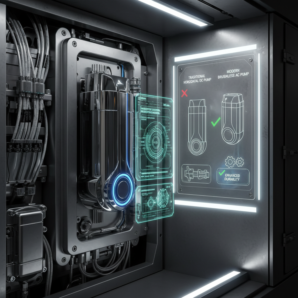
6.1 Advanced Pump Design Architectures
A significant trend is the shift from traditional horizontal DC motor configurations to advanced vertical AC models with integrated inverters. These newer designs offer marked improvements in reliability, maintenance requirements, and application flexibility.
Comparison of Traditional vs. Modern Soak Back Pump Designs:
| Feature | Traditional DC Horizontal Pump | Modern AC Vertical Pump |
|---|---|---|
| Motor Type | DC motor (e.g., 74 VDC) | Brushless AC motor with built-in inverter |
| Power & Speed | 3/4 HP at 1200 RPM | 3/4 HP at 1200 RPM |
| Flow Rate | 3-6 GPM | 3-7 GPM |
| Working Pressure | 40 PSI minimum | 40 PSI minimum |
| Mounting & Weight | Horizontal, heavier | Vertical, ~30 lbs |
| Engine Compatibility | 645 Engine series | 645 and 710 Engine series (V-16) |
| Durability Claim | Standard intervals | Enhanced durability up to 6 years |
| Cooling Method | Conventional | Self-cooling using diesel as a medium |
The advantages of the vertical AC design are substantial. Brushless induction motors eliminate the need for brush replacement, directly reducing maintenance costs and downtime. The integrated inverter and protective circuitry enhance reliability in environments prone to voltage fluctuations. Furthermore, the compact, vertical footprint simplifies installation in crowded engine rooms.
6.2 Integration with Automatic Engine Start/Stop (AESS) Systems
The proliferation of Automatic Engine Start/Stop systems, which shut down the main engine during prolonged idling to save fuel, creates a unique challenge. Soak back pumps must now be engineered for dramatically increased start/stop cycles without performance loss.
Key Design Features for AESS Compatibility:
- Robust Cycling: Components must endure hundreds of additional annual cycles.
- Intelligent Control: Seamless integration with the Locomotive Control Computer (LCC) is essential for coordinating pre-lubrication before an automatic restart.
- Thermal Management: Liquid-cooled electronics are critical to prevent heat-related failures during potentially extended pump run times.
- Longevity: Pumps are being designed for maintenance-free lives of up to 10 years in heavy-duty service to match extended maintenance intervals.
6.3 Optimization Through Adaptive Control and Monitoring
Future systems are moving beyond simple timers toward adaptive control based on real-time conditions. The standard 35-minute maximum runtime, as controlled by the LCC, may be optimized dynamically.
Potential Adaptive Control Strategies:
| Control Parameter | Fixed Approach | Adaptive Optimization |
|---|---|---|
| Run Time | Fixed duration (e.g., 35 min) | Variable based on measured turbocharger temperature decay. |
| Activation Trigger | Engine-off signal | Temperature-based activation threshold. |
| System Integration | Standalone operation | Coordinated with engine cooling and lube oil systems. |
| Health Monitoring | Periodic manual checks | Continuous pressure and vibration trending for predictive maintenance. |
This shift enables condition-based maintenance. For instance, performance monitoring of pump pressures can indicate developing blockages in the turbocharger oil passages. Regular lube oil analysis, a cornerstone of comprehensive maintenance programs, provides essential data on wear metals and oil condition, informing decisions about pump and filter service.
6.4 Focus on Reliability and Service Life
The overarching goal of these developments is to create a “fit and forget” component with exceptional reliability. Key design features contributing to this goal include:
- Hardened pump bodies and gears to maximize longevity under continuous or frequent cycling.
- Continuously lubricated, self-cleaning bearings for consistent performance over the pump’s lifespan.
- Standardized capacities and pressures (e.g., 13 LPM / 3.5 GPM at 40 PSI) that meet core protection requirements while allowing for customization in size and voltage as needed.
The trajectory of soak back pump development is clear: integration of more durable materials, intelligent and connected control systems, and designs tailored for the specific demands of modern, efficiency-focused locomotive operations. This evolution ensures that the soak back pump will continue to be a critical, yet increasingly reliable, guardian of turbocharger longevity.