
The turbo soak back pump model 40182032 represents a critical advancement in locomotive turbocharger management, designed specifically to address one of the most persistent operational challenges in modern diesel locomotive maintenance: oil coking within turbocharger bearing assemblies during engine shutdown cycles. This specialized pump operates as an auxiliary lubrication and cooling system that continues delivering filtered oil to turbocharger bearings after main engine operation has ceased, preventing the thermal breakdown of lubricating oil that would otherwise accumulate as carbon deposits on critical bearing surfaces.
Understanding proper installation procedures for this component is essential for locomotive maintenance personnel and operations managers seeking to maximize engine reliability, extend turbocharger service intervals, and minimize unplanned downtime that directly impacts operational budgets and scheduling efficiency.
Fundamentals of Turbocharger Lubrication and the Soak Back System
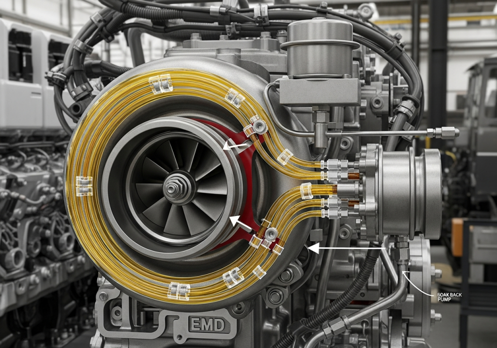
Turbochargers in EMD locomotive engines operate under extreme conditions that fundamentally differentiate them from typical stationary engine applications. The turbine wheel routinely reaches temperatures approaching 1000°F (538°C), while the entire rotating assembly spins at velocities exceeding 100,000 RPM in standard operation. These extreme parameters create an environment where bearing lubrication and cooling become absolutely critical to component longevity and overall engine reliability. Unlike automotive turbochargers that experience intermittent operation patterns, locomotive turbos must sustain continuous high-speed rotation for extended periods, followed by relatively rapid shutdown sequences that present unique thermal challenges.
The conventional main lubrication system in a turbocharged locomotive engine supplies pressurized oil to turbocharger bearings during engine operation through the primary oil gallery network. However, this system operates only when the engine is running and generating sufficient oil pressure.
The moment an engineer reduces throttle and the diesel prime mover transitions toward shutdown, the main lube oil pump discharge pressure decreases dramatically, eventually ceasing entirely when the engine stops. At this precise moment, the turbocharger rotor assembly continues spinning due to inertia, but without adequate oil supply for cooling and bearing lubrication. The residual exhaust heat absorbed by the turbine wheel and rotor shaft creates what engineers call a “coking environment”-conditions where the thin film of oil remaining in the bearing housing exceeds its thermal stability threshold and breaks down into carbonaceous deposits.
The soak back oil system, including the auxiliary pump model 40182032, was developed specifically to eliminate this vulnerability. Unlike the engine-driven main lube pump that depends on crankshaft rotation, the soak back pump operates via independent electric motor power (either AC or DC configuration) controlled by the locomotive’s computer management system.
When an engineer shuts down the diesel engine, the locomotive control computer automatically energizes the soak back pump motor, which continues drawing filtered oil from the main engine sump and directing it through a dedicated soak back filter directly into the turbocharger bearing cavity. This continuous low-pressure oil circulation removes residual heat from the turbo rotor assembly and prevents oil thermal degradation that would otherwise create damaging carbon buildup. The pump operates automatically for approximately 30 to 35 minutes following shutdown, allowing the turbocharger to cool naturally while maintaining proper lubrication.
The pump also provides essential pre-lubrication before engine startup. When an engineer initiates the starting sequence on a turbocharged locomotive, the soak back pump activates several minutes before fuel injection begins, ensuring that turbocharger bearings are already bathed in fresh oil when the diesel engine fires and the turbo begins accelerating toward operating speed. This pre-lubrication dramatically reduces initial bearing wear during the critical startup phase when bearing surfaces experience metal-to-metal contact if oil is not present.
The Critical Problem: Oil Coking and Bearing Degradation
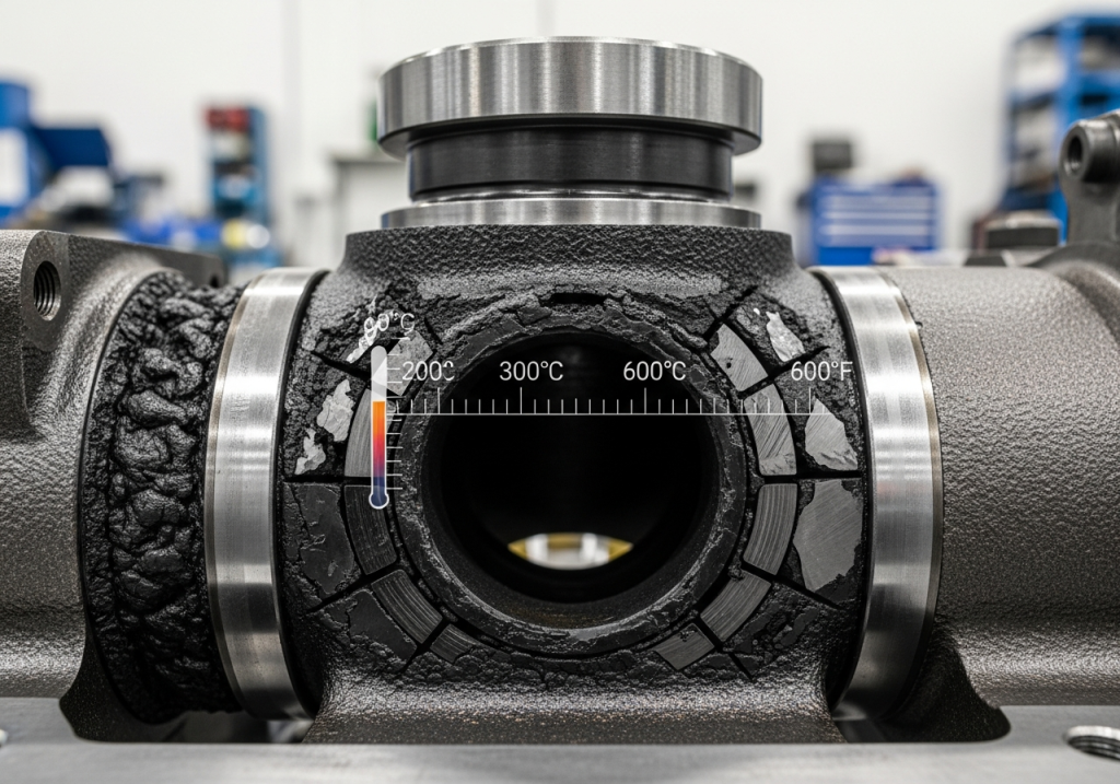
Oil coking within turbocharger bearing housings represents one of the most insidious failure mechanisms in locomotive diesel engines, often progressing silently until catastrophic bearing seizure occurs. The fundamental chemistry driving oil coking is straightforward but severe: when mineral-based diesel engine oils are exposed to temperatures exceeding their thermal stability limits-typically above 300°C (572°F)-the hydrocarbon chains that form the oil’s molecular structure begin to crack and oxidize, creating complex polymeric compounds that solidify into coke residue. Within a turbocharger bearing housing where localized temperatures regularly exceed 400°F during operation and can spike to 600°F or higher near the turbine end during the post-shutdown cooling phase, these conditions are routinely encountered.
The process of coke formation and accumulation follows a predictable degradation pathway that maintenance personnel can identify through careful monitoring. Initially, oil oxidation produces organic acids and low-boiling-point compounds that evaporate, leaving sticky tar-like residues on bearing surfaces. As the turbocharger continues cooling without active oil circulation during the shutdown period, these residues are not flushed away by fresh oil flow; instead, they accumulate layer upon layer in the bearing clearance spaces. Over time-often measured in hundreds of operating hours rather than thousands-this carbon buildup restricts oil passages, reduces bearing film thickness, increases friction between rotating elements and bearing journals, and generates excessive localized heat that accelerates further coke formation in a vicious cycle.
The practical consequences of unchecked oil coking prove extremely costly for locomotive operations. As bearing clearances become progressively restricted by carbon deposits, bearing surfaces experience increased friction and wear, eventually leading to bearing seizure where the shaft locks against the journal bearing and rotation becomes impossible. At this point, the turbo cannot deliver compressed air to the engine, forcing operators to limp the locomotive to a maintenance facility at greatly reduced power output. More severely, shaft seizure can progress to actual shaft fracture if the engine is forced to higher notches after initial seizure, resulting in complete turbocharger destruction that requires full unit replacement rather than simple bearing service.
Analysis of failed turbochargers reveals the characteristic appearance of coking damage: bearing surfaces display distinctive bluish-yellow heat tinting where steel has been oxidized by extreme temperature exposure; the bearing material itself shows etched grooves and scoring patterns from particles of coke rubbing against precision surfaces; and in the most severe cases, the shaft itself displays plastic deformation and actual fracturing under the centrifugal loads it experiences while bearing surfaces are degraded and no longer capable of supporting rotational loads.
The soak back pump 40182032 directly prevents this failure mode by removing the post-shutdown thermal energy that drives oil coking. By continuously circulating fresh filtered oil through the turbocharger bearing cavity for 30-35 minutes after shutdown, the soak back system maintains bearing surface temperatures substantially below the threshold where significant oil degradation occurs. The fresh oil also displaces the carbon-laden oil that would otherwise remain in bearing clearances, replacing it with clean lubricant that will be present when the engine restarts.
Installation Procedures for Turbo Soak Back Pump Model 40182032
Pre-Installation Inspection and System Preparation
Successful installation of the soak back pump 40182032 begins well before the pump itself is physically mounted on the locomotive engine. The installation procedure represents one of the most critical maintenance operations affecting long-term turbocharger reliability, and any shortcuts or oversights during installation directly translate to premature failure risk. The first essential step involves comprehensive inspection of the existing soak back system components already present on the locomotive.
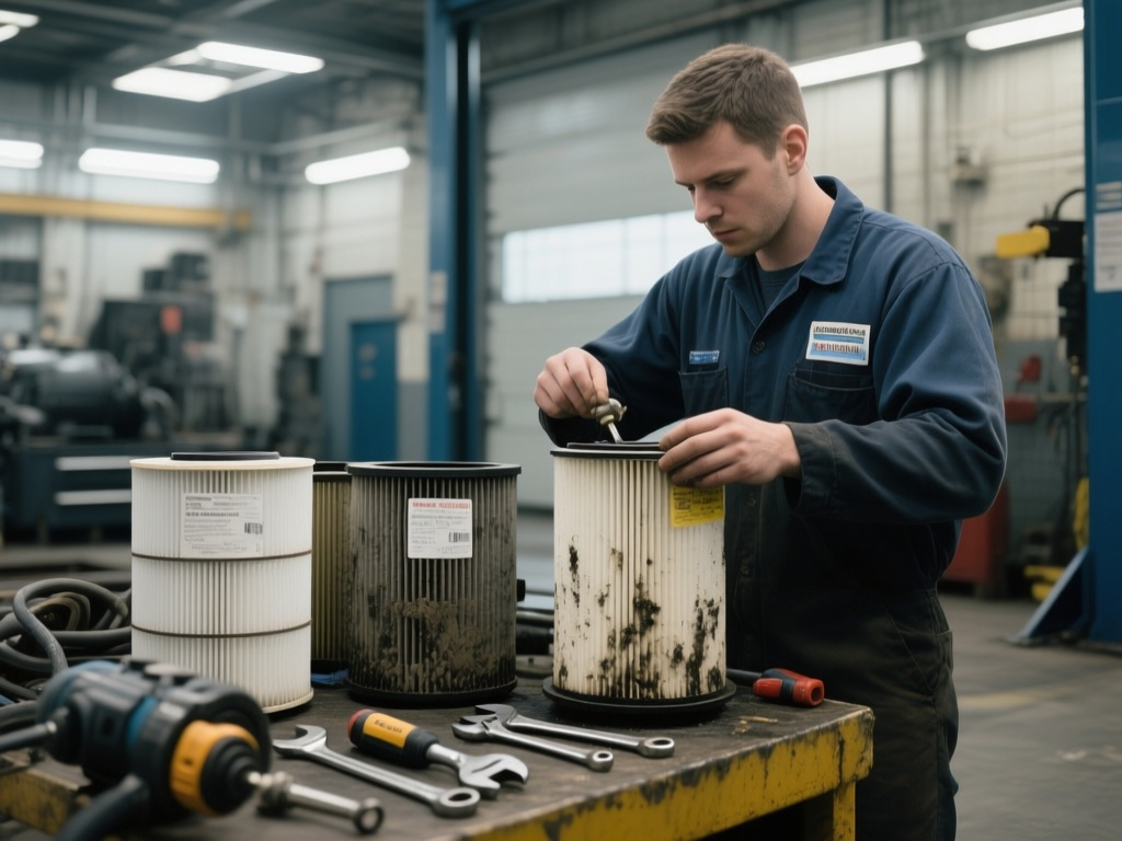
The soak back filter assembly must be examined carefully for signs of previous damage, corrosion, or internal blockage. If the filter element is heavily saturated with metallic particles or dark sludge deposits, this indicates that bearing wear has been occurring within the turbocharger and metal fines have been circulating through the soak back system. Such conditions demand not only filter replacement but also detailed inspection of the turbocharger itself for bearing damage before installation of the new pump. The check valves located in the turbocharger filter head assembly-which prevent soak back oil from entering the main turbocharger lubrication circuit when the main pump is operating-must be removed, cleaned thoroughly, and tested for proper cracking pressure.
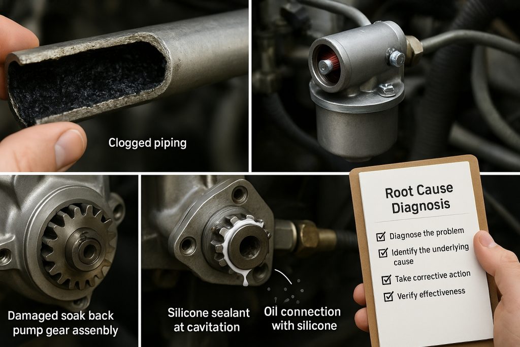
The soak back piping network between the pump outlet and the turbocharger filter assembly requires complete visual inspection for blockages, corrosion, or physical damage. Carbon deposits are particularly common in soak back feed lines, particularly near heat sources where oil has partially evaporated and left residue. If soak back piping appears to have internal blockage, the line must be cleaned using appropriate solvents and high-pressure air, or replaced entirely with new tubing if cleaning proves ineffective. Any kinked, crimped, or severely corroded sections must be replaced with new lines of identical diameter and routing to original specifications.
The electric motor that drives the soak back pump must be tested for proper operation before the new pump is installed. In locomotives with AC-powered soak back systems (which includes the 40182032 vertical type), the motor should be checked for proper voltage, continuity of motor windings, and mechanical freedom of the rotor. If the motor appears to have suffered water damage, corrosion of electrical connections, or does not spin freely when power is briefly applied, the motor must be replaced or professionally refurbished before new pump installation.
Physical Installation of Model 40182032
The soak back pump model 40182032, designated as a vertical-type AC motor-driven pump, must be mounted in a location where it is protected from excessive moisture, corrosive atmospheres, and direct contact with hot engine surfaces. On most EMD turbocharged locomotives, the soak back pump is typically mounted in the engine room on the right side of the engine block, positioned where the pump motor has adequate access to electrical power connections and the pump outlet has clear routing toward the soak back filter assembly.
The pump must be secured to its mounting surface using appropriate bolts and lockwashers that prevent vibration-induced loosening. All fasteners should be torqued to manufacturer specifications (typically in the range of 25-35 foot-pounds for motor mounting bolts, though specific values depend on the locomotive platform and EMD service bulletins). The pump inlet line must be connected to the engine oil sump using suction-line tubing of adequate diameter (typically 5/8 inch or larger) to ensure oil supply is not restricted. This inlet connection is critical because inadequate inlet line sizing creates suction conditions that can cavitate the pump, reducing output pressure and flow rate.
The outlet from the soak back pump flows into the soak back filter assembly, which contains multiple valves and check mechanisms that require precise installation. The soak back filter should be mounted horizontally if possible, with the filter element oriented vertically (perpendicular to the ground) to promote air entrapment to rise upward and exit the system.
The filter assembly contains several critical pressure relief and bypass valves that maintain safe operating conditions. A 32 PSI pressure relief valve prevents excessive system pressure from developing if the filter becomes partially restricted. A 70 PSI bypass valve allows soak back pump flow to bypass a completely plugged filter element, ensuring that the turbocharger continues receiving oil even if filter maintenance has been neglected. Both valves must be inspected, cleaned, and tested for proper cracking pressure before the soak back filter is placed in service.
The outlet from the soak back filter connects to the turbocharger filter head assembly through a dedicated line that must maintain clear, unobstructed flow to the turbocharger bearing cavity. This outlet line should be routed to avoid unnecessary bends, which can create turbulence and pressure drop. If the soak back outlet line must make multiple direction changes to reach the turbocharger, larger diameter tubing (typically 3/4 inch or larger) should be used to minimize pressure loss. The routing should also avoid positioning the line near hot exhaust components, which can cause partial evaporation of oil in the line and creation of vapor that reduces lubrication effectiveness.
Oil System Priming and Pressure Testing
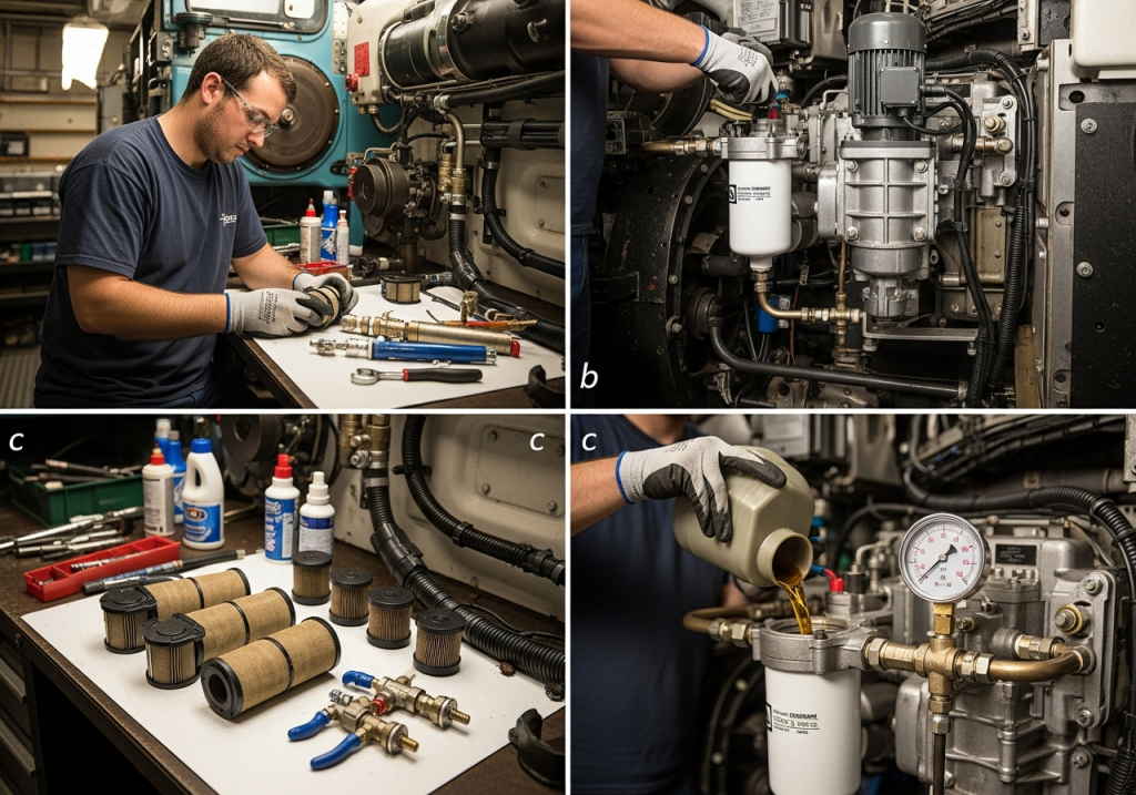
Following physical installation of the soak back pump and all associated piping, the system must be completely filled with clean engine lube oil and all air purged from the circuit before engine startup. This priming procedure is absolutely essential because operating the soak back system with air in the lines will create cavitation within the pump, drastically reducing pressure and flow, and potentially causing bearing oil starvation in the turbocharger.
The priming procedure begins by disconnecting the outlet line at the turbocharger filter head while keeping the line connected to the soak back filter outlet. Fresh, clean engine lube oil of the correct viscosity (typically SAE 30 or 15W-40 depending on ambient operating temperatures) is then poured directly into the soak back filter housing until it fills to the specified level (typically marked on the filter housing).
The pump is then briefly energized (with fuel disabled to prevent engine startup) to circulate oil through the filter and outlet line. This circulation continues until oil begins flowing from the disconnected turbocharger filter outlet line rather than air, indicating that air has been purged from the system. Once continuous oil flow is observed, the outlet line is reconnected to the turbocharger filter head, and the soak back filter is topped with additional fresh oil to bring the level back to the specified mark.
After physical priming, the soak back system pressure must be measured to confirm it is operating within manufacturer specifications. The test procedure involves installing a calibrated pressure gauge (0-100 PSI range) at the test point on the compressor bearing oil passage, typically located on the right side of the turbocharger. With the soak back pump operating and the main engine running at idle speed, the system pressure should read between 10 and 35 PSI. If pressure is below 10 PSI, this indicates blockage in the soak back piping that must be located and cleared before proceeding. If pressure exceeds 35 PSI, the relief valve in the soak back filter assembly may be set incorrectly or may have failed.
Operational Integration and Control System Configuration
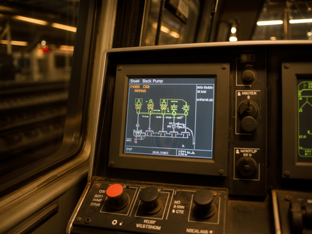
The soak back pump model 40182032 does not operate as a standalone component but rather as an integrated element within the locomotive’s overall engine management architecture, controlled by the locomotive control computer (LCC) that oversees all critical engine functions. The computer’s soak back logic automatically energizes the pump motor at two specific operational moments: during engine starting, several minutes before fuel injection begins, and continuously for approximately 30 to 35 minutes following engine shutdown, with the exact duration typically settable through locomotive service parameters.
During the startup sequence, the control computer activates the soak back pump as part of the pre-lube operation, ensuring that turbocharger bearings receive fresh oil before combustion begins and the turbo starts accelerating. This pre-lube phase typically lasts until main engine lube oil pressure rises above approximately 20 PSI, at which point the main oil pump begins delivering oil to the turbocharger and the soak back pump automatically shuts down. Once the main system pressure exceeds the soak back pump pressure (which typically operates at 10-35 PSI), a pressure-operated check valve in the soak back filter head prevents soak back oil from entering the main turbocharger circuit, preventing mixing of systems.
The post-shutdown soak back phase begins the moment an engineer initiates engine shutdown through the control stand. As main engine lube oil pressure drops below threshold values (typically falling as RPM decreases toward zero), the control computer senses this condition and automatically energizes the soak back pump motor. The pump then operates continuously, circulating oil through the turbocharger for the full 30-35 minute cooling period, before automatically shutting down after the preset timeout interval. During this critical post-shutdown period, the soak back oil circulation removes heat from the turbocharger rotor assembly and bearing cavity, preventing the oil coking that would otherwise occur if residual heat were left uncontrolled.
Critically, the control system logic prevents the soak back pump from being manually shut down or interrupted during its post-shutdown operational phase, even if maintenance personnel need to access other engine systems. Interrupting the soak back cycle before the full 30-35 minute period has elapsed will leave the turbocharger incompletely cooled, potentially allowing oil coking to occur. Maintenance manuals specifically warn against performing other maintenance tasks during the soak back cooling period; if emergency work is absolutely necessary, the complete soak back cycle must be restarted after the work is finished.
Maintenance Protocols and System Validation
Filter Replacement and Element Service
The soak back filter element requires replacement at regularly scheduled intervals to prevent degradation of system performance. The manufacturer-recommended replacement interval for the turbo lube oil filter and soak back filter is typically every 1,400 operating hours or 90 calendar days, whichever occurs first. However, if the locomotive operates in particularly dusty environments, operates extensively at idle (where oil circulation is minimal), or has experienced recent turbocharger bearing wear, filter replacement intervals should be shortened to every 45 days or sooner.
When replacing the soak back filter element, both the turbo lube filter and soak back filter should always be changed together using identical replacement intervals. This coordinated replacement prevents the situation where one filter becomes progressively more restrictive while the other is fresh, which can cause imbalanced pressure conditions. The replacement filter element must be of original equipment quality that meets or exceeds OEM specifications; substituting lower-cost aftermarket filters risks introduction of finer particles into the turbocharger bearing system.
Check Valve Testing and Replacement
The check valves integrated into the turbocharger filter head assembly-which prevent backflow between the soak back system and main lube oil circuit-must be periodically removed, cleaned, and inspected. These valves are spring-loaded and rely on precise calibration to prevent oil from entering the soak back system when the main pump is pressurized. If one of these valves becomes stuck in the open position, main lube oil will flow backward through the soak back circuit during engine operation, creating abnormally high pressure in the soak back filter assembly and potentially damaging the relief valve.
The check valve test is straightforward but requires careful attention: with the engine shut down and the soak back pump operating, an operator should open the top engine deck cover and visually observe the camshaft area to ensure that no oil is being pumped down onto the camshaft bearings. If oil is observed dripping on the cams during soak back operation, this definitively indicates that one or both of the turbocharger filter head check valves are stuck open or installed backward, and they must be removed and serviced immediately.
System Pressure Validation
Regular pressure testing of the soak back system-recommended at six-month intervals or whenever turbocharger service is performed-provides early warning of developing problems before complete system failure occurs. The pressure test replicates the manufacturer’s installation procedure: a calibrated 0-100 PSI pressure gauge is temporarily installed at the compressor bearing oil passage test point, the soak back pump is energized, and pressure readings are recorded at idle RPM and at higher engine speeds.
Healthy soak back systems typically produce 10-35 PSI of pressure during operation. Pressures below 10 PSI indicate that the soak back piping is partially blocked by carbon deposits or that the pump itself is failing (delivering inadequate flow). Pressures above 35 PSI during low-flow conditions suggest that the relief valve in the soak back filter assembly has degraded or lost calibration. Either condition warrants immediate corrective action, as operating with abnormal pressure conditions risks either oil starvation in the turbocharger (low pressure) or rupture of the soak back filter housing (excessive pressure).
Common Installation Errors and Troubleshooting Procedures
The history of soak back system installation across numerous locomotive fleets has revealed a consistent pattern of errors that compromise system performance and lead to premature failures. Understanding these common mistakes enables maintenance personnel to avoid repeating them and to diagnose existing problems accurately.
Contamination Left in Piping from Previous Maintenance: Among the most frequent installation errors is failure to thoroughly flush the soak back piping before installing the new pump. When a previous soak back pump is removed for service or replacement, carbon deposits and oxidized oil residue inevitably remain within the feed and return lines. If these contaminated lines are not cleaned with solvent and compressed air before the new pump is installed, the residual contamination immediately enters the new pump and circulates directly into the turbocharger.
Within hours or days of operation, this contamination clogs the fine passages within the turbo bearing cavity, progressively restricting oil flow until bearing oil starvation occurs. The solution requires complete removal of soak back piping, thorough cleaning with petroleum solvent and compressed air, and reassembly of cleaned components or installation of entirely new piping.
Inadequate Oil Priming Before Startup: The second most common installation error involves starting the engine without properly priming the soak back system with oil. When air becomes trapped in the pump inlet line or soak back filter housing, the pump initially operates on air and creates cavitation conditions rather than positive oil displacement. Even a few seconds of cavitation can damage the pump’s internal gears and dramatically reduce future pump output, and more importantly, oil starvation conditions exist in the turbocharger during this brief period. Proper procedure requires complete filling of the soak back filter with fresh oil before engine startup and verification of oil flow from the disconnect point at the turbocharger filter outlet before connection is completed.
Incorrect Filter Element Installation: The soak back filter housing must always be positioned with the inlet port below the filter element and the outlet port above it, allowing air to naturally rise and escape rather than becoming trapped. If the housing is installed sideways or inverted, air bubbles will be trapped within the filter element, creating vapor pockets in the oil flow that reduce pressure and flow rate. Upon engine startup, these trapped air bubbles suddenly expand due to pressure reduction, creating cavitation conditions within the turbocharger bearing cavity.
Reusing Original Filter Elements: Some maintenance shops attempt to clean and reuse the soak back filter element from previous service, rather than replacing with a new element. Soak back filter elements are constructed with thin paper media designed to trap particles at the micron level; once the element has been exposed to engine operation, the fibers become compacted and cannot be effectively restored to original specifications through cleaning. Additionally, microscopic particles become embedded within the paper fibers and cannot be reliably flushed out, meaning that reused elements introduce contamination directly into the turbocharger.
Silicone Sealant at Oil Connections: A particularly damaging mistake involves using silicone RTV sealant instead of proper gaskets at any oil connection point in the soak back circuit. Silicone sealant inevitably particles break loose from the cured material and circulate through the oil system, creating blockages in the turbocharger bearing oil passages. The solution requires removing the silicone, thoroughly flushing the affected lines with solvent, installing proper gaskets or O-rings, and reflushing the system.
Neglecting to Diagnose Root Cause of Previous Failures: If a soak back pump or turbocharger required replacement due to failure, installation of a new pump without diagnosing why the previous unit failed will inevitably result in identical failure of the replacement. If the original failure was caused by blocked soak back piping, installing a new pump in the same contaminated piping simply sets up another failure. Similarly, if the previous turbocharger was damaged due to inadequate soak back cooling, the root problem (which may involve inadequate pump flow or system leakage) must be corrected before expecting the new turbocharger to perform reliably.
Integration with EMD Locomotive Engine Systems
The soak back pump model 40182032 is specifically engineered for integration with EMD turbocharged engines of the 567/645 family and their successors (645E3 variants). Understanding how the soak back system interfaces with the overall engine lube oil architecture is essential for proper installation and operation.
EMD turbocharged engines feature multiple independent oil circuits, each with its dedicated pump and pressure requirements. The scavenging oil circuit removes oil from the crankcase and supplies it to the main oil pump; the piston cooling circuit delivers a portion of main oil to cool the piston crown undersides through small jets; the main lubricating oil circuit pressurizes all bearing surfaces; and the soak back circuit provides auxiliary lubrication independent of main engine operation.
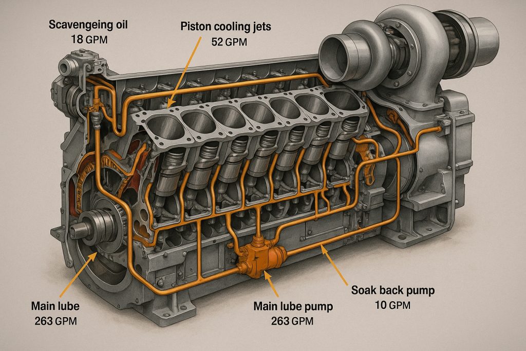
Each circuit operates at distinct pressure levels: the scavenging pump delivers approximately 1,700 liters per minute, the piston cooling pump approximately 413 liters per minute, the main lube pump approximately 867 liters per minute, and critically, the soak back pump delivers only approximately 11 liters per minute. This dramatically lower flow rate is intentional-the soak back system is designed for cooling and light lubrication during shutdown, not for providing the full flow required during active engine operation.
The pressure relief valve installed in the soak back filter assembly (set at 32 PSI) prevents excessive system pressure from developing. When the main engine lube oil pressure rises above the soak back system pressure during engine starting, a check valve in the turbo filter head housing automatically closes, isolating the soak back circuit and preventing interaction between the two systems. This isolation ensures that normal engine operation proceeds with optimal pressure control from the main system, while the soak back system remains available to activate only when the main pump ceases operation.
Performance Monitoring and Predictive Maintenance
Beyond the basic maintenance schedule of regular filter replacement and periodic pressure testing, sophisticated locomotive operators implement condition-monitoring programs that use lube oil analysis to detect early signs of turbocharger bearing degradation. Oil samples drawn from the engine sump are sent to specialized laboratories where spectrographic analysis quantifies the presence of iron, copper, aluminum, and other elements that correlate with specific wear mechanisms.
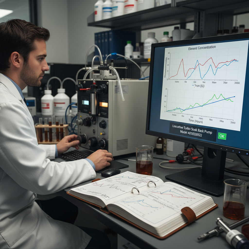
Elevated iron content indicates bearing wear; elevated copper suggests bearing cage degradation; elevated aluminum points to piston wear rather than bearing issues. By tracking trends in these element concentrations over time rather than looking at single absolute values, maintenance engineers can identify developing problems while they remain manageable and schedule corrective maintenance during planned service windows rather than facing catastrophic failure during revenue operations.
The most advanced monitoring programs establish baseline oil analyses for each specific locomotive and then track deviations from that baseline rather than applying generic thresholds. This approach is superior because locomotive fleets typically include units of various ages and service histories; what represents normal wear for an older engine might indicate accelerated degradation in a newer unit. When laboratory analysis identifies significant changes compared to previous samples, the operator can schedule turbocharger inspection and preventive bearing service before performance impacts occur.
Regulatory Compliance and Emissions Considerations
Modern locomotive diesel engines must comply with stringent environmental regulations that impose limits on particulate matter and oxides of nitrogen in exhaust gases. The soak back system actually provides a secondary benefit relative to emissions compliance: proper cooling of the turbocharger through the soak back system prevents oil from reaching the exhaust gas temperatures where it would burn and generate particulate smoke. Locomotives that have inadequate soak back system maintenance often display excessive black smoke during startup and acceleration, which indicates incomplete combustion and loss of particulate matter control.
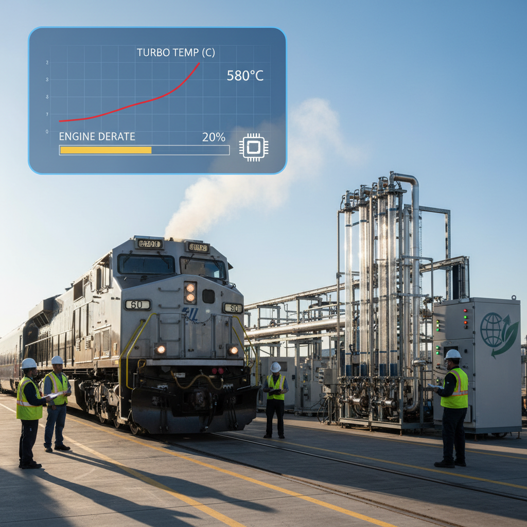
Engine control system software typically incorporates monitoring of turbocharger bearing temperature using sensors that measure oil temperature in the turbo filter head assembly. If bearing temperatures rise above threshold values-indicating inadequate cooling due to soak back system failure-the engine control computer will typically derate engine power output to prevent further heat accumulation. Understanding these protective automatic derates helps maintenance personnel diagnose soak back system problems: an unexpected reduction in available horsepower during normal operation often indicates turbo bearing overtemperature conditions caused by soak back system failure.
Conclusion
Installation and maintenance of the turbo soak back pump model 40182032 represents one of the most critical technical skills required in modern locomotive engine maintenance. This specialized component directly prevents oil coking-one of the most destructive failure mechanisms affecting locomotive turbochargers-through continuous circulation of filtered cooling oil during engine shutdown cycles and pre-startup lubrication during engine starting. The proper installation procedure involves comprehensive preparation of the soak back system components, careful physical mounting of the pump with attention to electrical connections and oil line routing, complete priming of the system with fresh oil prior to initial operation, and validation through pressure testing that confirms proper system function.
Beyond installation, long-term reliability depends on disciplined adherence to the maintenance schedule: replacing filter elements at specified intervals, periodically testing check valve function and system pressure, diagnosing and correcting root causes of any previous failures, and avoiding the common installation errors that have been repeatedly demonstrated to compromise system performance across multiple locomotive fleets. Organizations that treat the soak back system as a critical element deserving systematic attention-rather than as an auxiliary component to be serviced only during major turbocharger overhauls-consistently achieve superior turbocharger reliability and substantially reduced unplanned maintenance costs.
The technical expertise required to properly install and maintain this system is not trivial, but the operational consequences of inadequate care are severe and expensive. Turbochargers damaged by oil coking or inadequate cooling require complete replacement rather than simple service, with costs measured in thousands of dollars per unit plus substantial downtime impacts. Conversely, disciplined attention to soak back system installation and maintenance provides protection against this failure mode that is proportionate to the investment required. For locomotive maintenance organizations seeking to maximize engine reliability, extend service intervals, reduce unplanned downtime, and optimize operational cost-effectiveness, proper installation and maintenance of the turbo soak back pump model 40182032 represents a fundamental best practice that directly impacts overall fleet performance and profitability.