
You’ll identify D87 traction motor bushings by verifying standard dimensions of .713 x 1½ inches for D87B variants and confirming brass material composition through visual inspection. Check mounting positions within the support bearing housing between wick lubricator systems and bearing surfaces—standard D87 units contain visible brass bushing assemblies, while D87BTR models use sealed tapered roller bearings without traditional bushings. Cross-reference part numbers like E9550251 against EMD documentation and measure tolerances within ±0.001 inches using calibrated micrometers. The following sections outline complete identification protocols across all motor configurations.
Key Takeaways
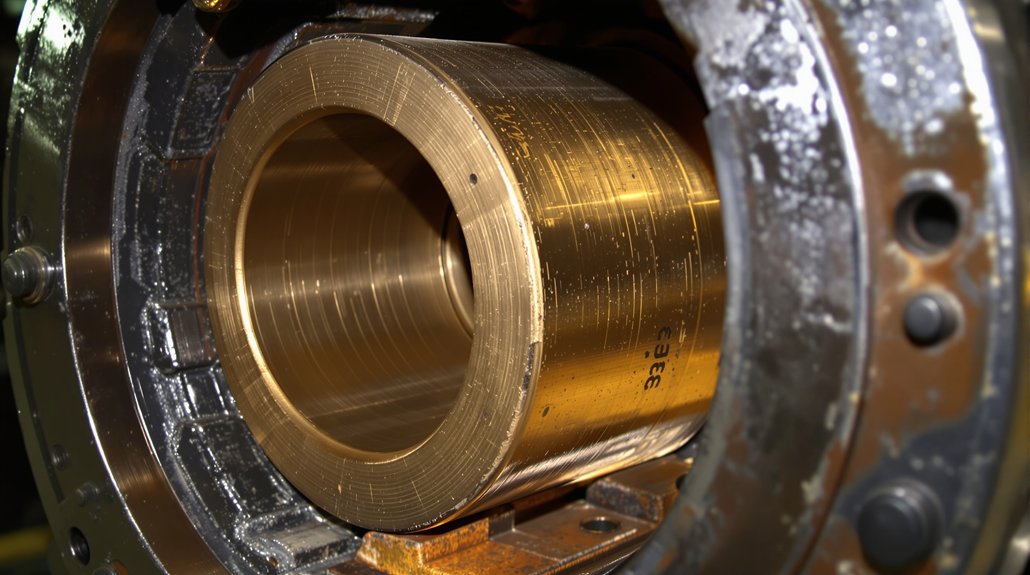
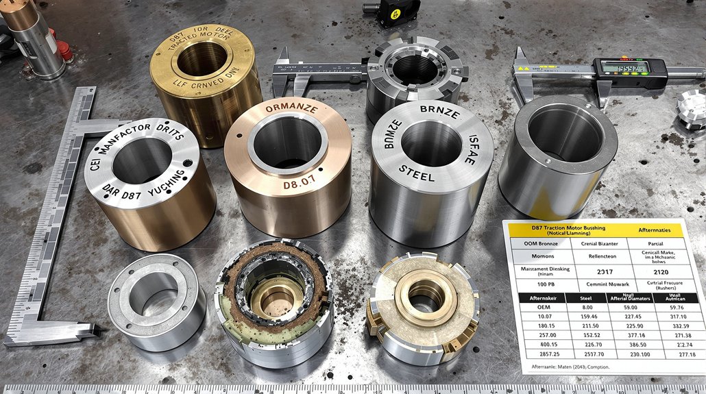
- D87 bushings are brass assemblies located within support bearing housing between wick lubricator systems and bearing surfaces.
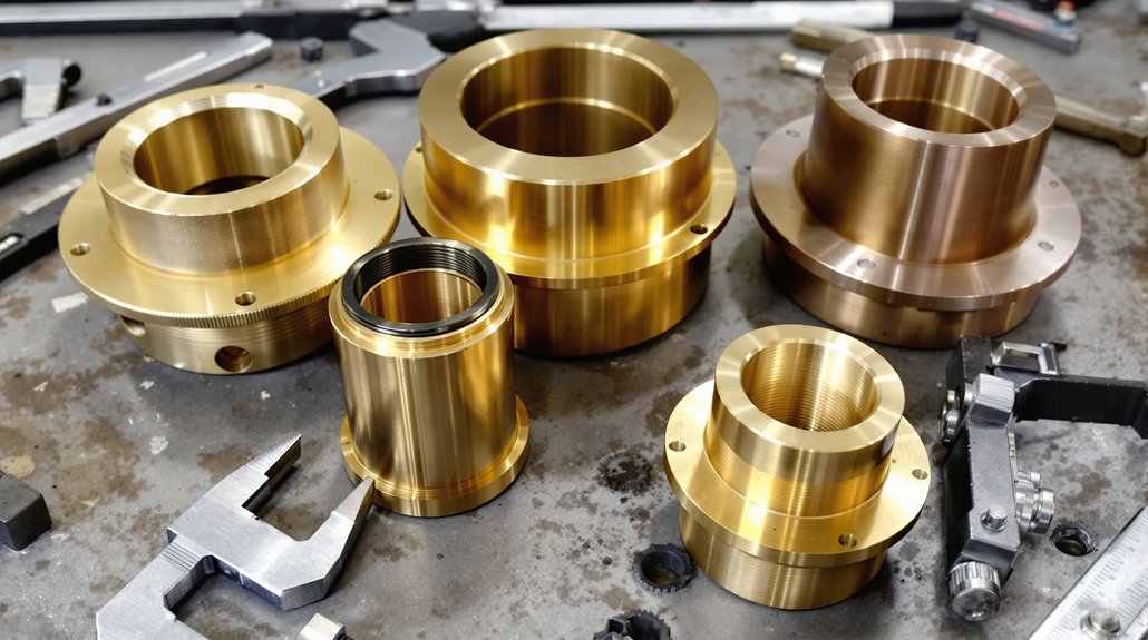
- Standard D87B traction motor bushings measure .713 x 1½ inches with tolerances maintained within ±0.001 inches.
- D87 bushings are matched to 83 HP motors with 62:15 gear ratio, distinguishing them from D78 or D100 series.
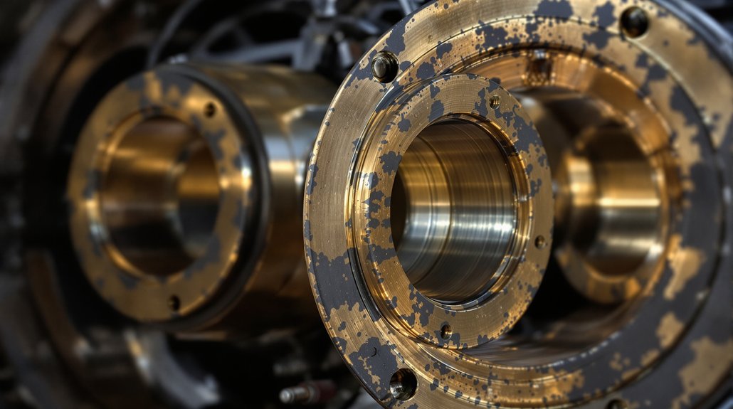
- Visual inspection reveals brass bearing components with integrated bushings, unlike D87BTR models with sealed bearing housings.
- Verify material hardness ranges from 60-65 Rockwell C for bronze alloys meeting manufacturer specifications.
Understanding D87 Traction Motor Frame and Bearing Housing Configuration
The D87 traction motor‘s frame assembly forms the structural foundation for a precisely engineered 62:15 gear ratio system rated for 83 HP brakehorsepower operation. You’ll find the frame manufactured through integrated casting and CNC machining processes, accommodating both D87 and D87B variants for different locomotive applications.
The bearing housing configuration incorporates pinion-end and commutator-end axle caps, complete with bearing caps, retainers, and seals. You must maintain critical dimensional tolerances, including the 43.875 ± .010 inches measurement between axle gear hub face and opposite wheel hub face. Load distribution depends on support bearing flanges with smooth thrust surfaces, while thermal expansion considerations require 16 micro-inches maximum surface finish on wheel and gear hub faces.
Your bearing housing system integrates with the gear case mounting structure and suspension bearing oil overflow systems. Verify dimensions using accurate dial indicator measuring devices and permanent master calibration stands for consistent quality control during assembly operations. The armature assembly requires complete winding with precision-manufactured laminations and coil supports to ensure proper electromagnetic function within the motor housing.
Locating Bushing Assemblies in Standard D87 Versus D87BTR Models
Zeroing in on bushing assembly locations requires understanding the fundamental architectural differences between standard D87 and D87BTR traction motors. You’ll find brass bushing assemblies integrated within the support bearing housing on standard D87 units, where they maintain bearing alignment with the axle wheel gear assembly. These bushings sit between the wick lubricator system and the brass bearing surfaces, accounting for thermal expansion during operation.
In contrast, D87BTR models eliminate bushing components entirely. You won’t locate traditional bushing assemblies because sealed tapered roller bearings mount directly to the axle housing. This configuration removes intermediate brass components while maintaining identical box size dimensions.
Visual inspection reveals the distinction: standard D87 motors display visible brass bearing components with integrated bushings, while BTR variants show sealed bearing housings without bushing interference points. This architectural modification simplifies wheelset removal, as BTR axle assemblies extract complete with suspension bearings rather than requiring bushing disassembly procedures. The D87BTR design fits E, F, and switcher frames interchangeably, making it adaptable across multiple locomotive platforms without structural modifications.
Part Number Reference Guide for D87 Motor Bushings
You’ll need to reference specific EMD part numbers to identify standard D87 bushings, as each position in the motor assembly carries distinct numerical identifiers. The D87BTR variant requires additional conversion bushing specifications that differ from standard configurations, necessitating careful cross-reference verification. Cross-reference compatibility charts from suppliers like Supco Canada Railway Supply and PowerRail enable you to match OEM numbers with aftermarket equivalents across drive end, commutator end, and armature shaft positions. Manufacturers can provide complete brand-new traction motors and armatures equivalent to EMD D87B and D87BTR specifications for comprehensive replacement solutions.
Standard D87 Bushing Numbers
Locating accurate part numbers for D87 traction motor bushings requires consulting EMD’s official documentation, as these components use specific identification systems that vary by bushing location and application. You’ll need to reference technical manuals that outline bushing specifications based on their mounting position within the motor assembly. Each bushing type corresponds to particular load requirements and operational parameters.
When identifying bushings, you must consider material selection criteria, as bronze, brass, and composite materials serve different friction and wear characteristics. Installation torque specifications accompany each part number designation, ensuring proper fit and preventing damage during assembly. Contact authorized EMD parts distributors or access official service bulletins to obtain current part number cross-references. Replacement bushings sourced from ISO/QS/TS certified suppliers offer quality standards comparable to original equipment when obtained through approved vendors. Maintain detailed records of bushing replacements, documenting part numbers for future maintenance cycles and inventory management.
BTR Conversion Bushing Specifications
Converting to BTR (Bearing Type Roller) specifications marks a significant departure from standard D87 bushing configurations, as the modification eliminates traditional brass support bearings and associated wick lubrication assemblies entirely. You’ll find the roller upgrade simplifies wheelset removal through specialized housing modifications while extending bushing maintenance intervals from 45 to 90 days for visual inspections. UCRS manufactures components to OEM print specifications ensuring dimensional accuracy and material compliance for all BTR conversion parts.
| Component | Part Number | Application |
|---|---|---|
| Housing-Pinion End Bearing | N8300137 | D87 BTR Conversion |
| D87B Bushing | E9550251 | .713 x 1½” Configuration |
| Axle Bearing Housing | BTR-Specific | Complete Wheelset Assembly |
D87-BTR designations identify bearing type roller conversion configurations within the part numbering system. You’ll maintain compatibility with D78/D87 platforms while achieving improved reliability and reduced maintenance costs through tapered roller support bearings.
Cross-Reference Compatibility Chart
When selecting replacement bushings for D87 traction motors, understanding manufacturer cross-references prevents costly ordering errors and reduces equipment downtime. You’ll find D87 and D87B motors share identical mounting configurations, while D78/D87BTR conversion bushings maintain backward compatibility with standard housings. GE 752 series components require adapter configurations for proper fit.
Materials compatibility becomes critical when cross-referencing between manufacturers—EMD’s 550V/1065A specifications demand specific bushing materials regardless of part number origin. Mikura International maintains extensive databases showing which installation tools work across different numbering systems. Verify M-1003 quality standards compliance when using cross-referenced parts to meet Class I railroad approval requirements for your specific application.
Visual Inspection Techniques for Bushing Identification
Carrying out a thorough visual inspection begins with examining the bushing’s wear patterns under adequate lighting conditions. You’ll need to identify visual cues indicating operational stress through circumferential scoring marks, radial cracking patterns, and color variations on brass surfaces. These indicators reveal critical information about alignment issues, heat damage, and excessive friction. Material identification becomes straightforward when you recognize specific brass surface characteristics, corrosion patterns, and oxidation marks unique to D87 components.
Document your findings using this systematic approach:
- Measure wear depth at multiple circumferential points using precision calipers to establish baseline conditions
- Check bore and outer diameter dimensions against manufacturer specifications for proper fit tolerances
- Examine oil distribution grooves for blockages, debris accumulation, or wear affecting lubrication pathways
- Inspect bushing-to-housing interface for excessive clearance, scoring damage, or alignment deviations
You’ll capture dimensional variations and surface condition data essential for replacement planning decisions. Maintain detailed maintenance logs of all findings and activities to support trend analysis and enable predictive maintenance strategies for future inspections.
Distinguishing D87 Bushings From D78 and D100 Series Components
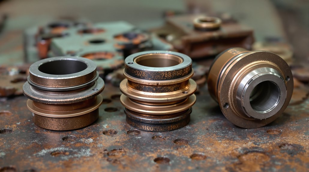
Physical inspection alone won’t guarantee correct bushing identification—you must understand the dimensional and design distinctions between D87, D78, and D100 series components.
D87 bushings accommodate specific load characteristics matching the 83 HP motor‘s 62:15 gear ratio configuration. These differ notably from D78 components designed for 700 HP output motors with 58:19 gearing. You’ll find D78 bushings feature modified copper conductor interfaces requiring different thermal coatings than D87 applications.
D100 series bushings incorporate ventilated coil support compatibility, distinguishing them from earlier D87 designs. Installation torque specifications vary between series due to frame casting and CNC machining differences. BTR conversions eliminate brass support bearings entirely, requiring alternative bushing mounting approaches.
Compare armature coil insulation materials—D87 and D78 utilize different silicone and mica technologies affecting bushing thermal management requirements. D100 upgrades demand modified commutator interfaces, creating distinct bushing dimensional parameters incompatible with standard D87 applications.
Measuring Bushing Dimensions and Specifications
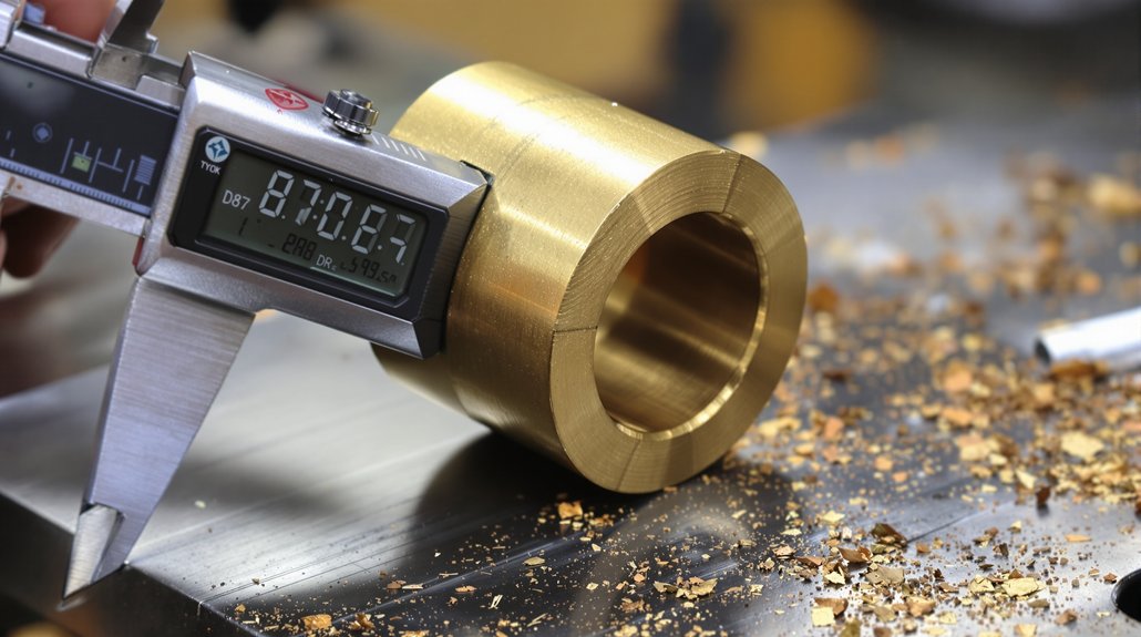
You’ll need precise measurement tools—including micrometers and calipers—to verify D87 bushing dimensions against OEM specifications. Standard D87B traction motor bushings measure .713 x 1½ inches, while brush holder bushings range from ½ x 1 inch to ¾ x 2¼ inches depending on motor configuration. Tolerance specifications must maintain strict adherence to M-1003 approved standards, as deviations beyond acceptable limits compromise motor performance and service life. All components should be cleaned in parts washers and vacuum dried before reassembly to ensure proper fit and function.
Standard Bushing Measurement Techniques
Accurate measurement of D87 traction motor bushings requires precision instruments and systematic techniques to verify compliance with EMD specifications. You’ll need to make certain proper tool calibration using calibration blocks before measuring any components. Digital calipers and micrometers provide readings to 0.001 inches for outer diameter, inner diameter, and length verification. Apply thermal compensation adjustments when measuring components at different temperatures to account for material expansion.
Your measurement procedure should include:
- Outer diameter measurement using calibrated calipers at three points along the bushing length
- Bore diameter verification with pin gauges or bore measurement tools
- Wall thickness assessment using precision micrometers at multiple locations
- Shoulder depth measurement confirming proper seating specifications
Record all dimensional data on measurement sheets, comparing results against EMD D87 and D87BTR variant specifications to determine serviceability.
Tolerance Specifications and Limits
When working with D87 traction motor bushings, maintaining tolerances within ±0.001 inches guarantees proper bearing operation and prevents premature failure. You’ll need to account for thermal expansion during measurement, as operating temperatures can affect dimensional accuracy. Measure bushings at room temperature (68°F) for consistent baseline readings.
Critical specifications include inner diameter, outer diameter, and length measurements. You must verify material hardness meets manufacturer standards, typically ranging from 60-65 Rockwell C for bronze alloys. Document all measurements against OEM specifications to identify wear patterns.
Use calibrated micrometers and bore gauges for precise readings. Any deviation beyond tolerance limits requires bushing replacement. Check for concentricity and surface finish specifications, ensuring smooth bearing surfaces. Maintain measurement records for predictive maintenance scheduling and failure analysis.
Identifying Worn or Failed Bushings During Maintenance Intervals
During routine maintenance intervals, identifying worn or failed bushings in D87 traction motors requires systematic application of multiple inspection techniques to detect deterioration before catastrophic failure occurs. You’ll need to execute thorough assessments that reveal both visible and hidden defects compromising operational integrity.
Implement these critical evaluation procedures:
- Thermal imaging scans detecting thermal hotspots exceeding normal operating temperatures, indicating inadequate lubrication or excessive friction at bushing interfaces
- Vibration analysis measuring frequency patterns and amplitude deviations that signal misalignment or structural degradation
- Oil sampling protocols identifying lubricant degradation through metallic particle content and viscosity breakdown
- Dial indicator measurements verifying dimensional tolerances remain within the 43.875 ± 0.010 inches specification between axle gear hub face and opposite wheel hub face
Standard sleeve-type bearing systems require inspection every 45 days, while upgraded tapered roller configurations extend intervals to 90 days, ensuring consistent performance monitoring throughout service cycles. Monitoring vibration data trends over time enables detection of sudden changes that may signal imminent bushing failure requiring immediate attention.
Cross-Referencing OEM and Aftermarket Bushing Part Numbers
Successfully identifying correct replacement bushings for D87 traction motors demands methodical navigation of both OEM and aftermarket part numbering systems that frequently employ incompatible cataloging conventions.
EMD’s standardized 7-8 digit sequences, such as 9522827 for armature assemblies, serve as your baseline reference. Effective supplier mapping requires documenting multiple cross-references since accuracy varies markedly between vendors.
Cross-reference OEM part numbers against multiple aftermarket systems to ensure compatibility, as supplier cataloging conventions rarely align with EMD standards.
Don’t rely solely on numerical matching. Physical specifications, dimensional tolerances, and material compositions must align with OEM documentation. Account for superseded part numbers where revisions have replaced original specifications. Inventory reconciliation becomes critical when managing parts across regional distribution networks that assign different codes to identical components. Common bushing variants include Bushing Front, Bushing Body, Bushing Drive Gear and Stub Shaft, and Bushing Shaft, each serving distinct positioning requirements.
Frequently Asked Questions
What Torque Specifications Apply When Installing Replacement Bushings in D87 Motors?
You’ll apply bushing-specific torque values according to the manufacturer’s torque chart, as standard D87 specifications don’t directly address bushing installation. Axle cap bolts require 1200 ft-lbs, while cover bolts need 40 ft-lbs for associated components. You must use appropriate threadlocker grade on bushing retention hardware per engineering specifications. Always employ calibrated click-type torque wrenches following an “X” pattern sequence, and verify your measurements after initial operation to make certain proper retention and alignment.
Can D87 Bushings Be Reused After Wheelset Removal and Reinstallation?
You shouldn’t reuse D87 brass support bearings after wheelset removal due to significant reuse risks from wear and potential surface damage during disassembly. The removal process compromises bearing integrity, making replacement mandatory for safety compliance. Follow your inspection checklist to verify bearing housing condition and assess component wear patterns. Standard maintenance protocols require new sleeve-type bearings during reassembly to meet OEM specifications and maintain the 18-month warranty period.
Which Lubricants Are Recommended for D87 Motor Bushing Maintenance Procedures?
You’ll need lithium-soap based greases like Shell TM-H or Shell Cyprina 963 for D87 motor bushing maintenance. For high-temperature applications, you should use fully synthetic TMG Lubricant with synthetic ester formulations. When extreme pressure protection‘s required, select products containing high viscosity mineral oil blends with sulfur-phosphorus additives. Don’t use products with solid lubricants or chlorinated solvents. Pack bearing grease during initial application or rebuild procedures to make certain proper lubrication.
How Do Temperature Conditions Affect D87 Bushing Wear Rates During Operation?
Like metal expanding and contracting in a forge, you’ll find that elevated ambient temperature accelerates D87 bushing wear by reducing lubricant viscosity and increasing clearance tolerances. Thermal cycling—repeated heating and cooling cycles—causes dimensional changes that compromise bearing surfaces and promote microcracking. You must monitor operating temperatures between specified limits, as sustained exposure above 155°C (311°F) degrades bushing materials exponentially. Install temperature sensors at critical bearing locations to track thermal patterns systematically.
Are Special Tools Required for Removing Pressed Bushings From D87 Housings?
Yes, you’ll need specialized equipment for D87 bushing removal. A hydraulic puller with sufficient tonnage capacity is essential to extract pressed bushings without damaging the housing bore. You’ll also require a custom mandrel sized specifically for D87 bushings to guarantee proper alignment during extraction. Standard pullers won’t provide the precise fitment needed. Always verify your tooling specifications match D87 housing tolerances before attempting removal to prevent costly equipment damage.