
You’ll need to match forward current ratings exceeding 1,000A for heavy-duty EMD locomotives while ensuring reverse voltage capabilities meet your DC traction system requirements with 20-30% safety derating below maximum VRRM. Select fast-recovery diodes with synchronized recovery times to minimize switching losses in 12-pulse configurations. Consider thermal management through appropriate package selection—TO-208 for 600A+ applications—and verify vendor compliance with EN50328, IEC60146, and AAR certification standards. The complete selection process involves additional critical parameters and configuration strategies.
Key Takeaways
- Select diodes with forward current ratings exceeding 1,000A and reverse voltage ratings ≥1.2 times continuous operating voltage.
- Choose fast-recovery diodes with low reverse recovery time to minimize switching losses in high-frequency applications.
- Use TO-208 or bolt-mount packages (DO-4/DO-5) with proper thermal management for 600A+ traction system requirements.
- Ensure vendor compliance with EN 50328, IEC 60146, and AAR/RIA qualifications for railway applications.
- Consider 12-pulse parallel configurations to reduce harmonics and improve current sharing in EMD locomotive systems.
Understanding EMD Locomotive Power Requirements and Operating Conditions

EMD locomotives demand rectifier diodes that withstand extreme operational variability across power ranges from 1,350 hp in legacy FT models to over 4,000 hp in modern high-voltage IGBT systems. You’ll encounter 600V DC traction motor systems fed by AC generators through rectification circuits, where diodes convert high-voltage AC to stable DC for propulsion. Your locomotive efficiency depends on rectifiers managing transient voltage spikes during acceleration/deceleration cycles while maintaining thermal stability across 900-950 rpm engine speeds.
Consider traction control requirements when selecting diodes for 8-, 12-, 16-, or 20-cylinder configurations. You must account for regenerative braking‘s reverse power flow, which tests diode reverse recovery characteristics. Dynamic braking operations generate substantial heat, demanding robust surge capacity and vibration-resistant mounting. Temperature extremes, altitude variations, and electromagnetic interference challenge component durability. Your diode selection must comply with IEEE standards while supporting modular maintenance accessibility and fault tolerance through ground protective relays. Proper corrosion management strategies must be implemented during installation to prevent electrical contact degradation that could compromise rectifier performance over the locomotive’s operational lifespan.
Evaluating Forward Current and Reverse Voltage Ratings for Traction Applications

Forward current and reverse voltage ratings form the electrical foundation of your rectifier diode selection process, determining whether components can handle the power demands and voltage stresses inherent in EMD traction systems.
Your forward current selection must align with traction motor demands, typically requiring 1000+ A continuous capacity for heavy-duty locomotives. Calculate total current based on power requirements—277 kW ÷ 560 V equals 495 A maximum—then factor in regenerative braking peaks reaching 1050 A.
Forward current ratings must exceed 1000 A continuous capacity to handle traction motor demands and regenerative braking peaks in locomotive applications.
For reverse voltage ratings, match your traction system’s DC output requirements:
- 825 V systems for urban transit applications
- 1500-1650 V configurations for standard rail operations
- 3000-3300 V setups for heavy-haul locomotives
- Derating by 20-30% below maximum reverse voltage (VRRM) for safety margins
Select devices rated ≥1.2 times continuous operating voltage. Modern 3-phase generators require specialized rectifier configurations to ensure optimal power conversion efficiency. Apply 120% safety margins for transient currents during braking scenarios, ensuring compliance with EN50328/IEC60146 standards while maintaining ideal performance under dynamic operating conditions.
Analyzing Reverse Recovery Time and High-Frequency Performance Characteristics
While forward current ratings establish your diode’s steady-state capabilities, reverse recovery time determines performance during critical switching changes that define traction system efficiency. You’ll need to evaluate reverse recovery characteristics against your system’s switching frequency to minimize parasitic losses that accumulate during commutation cycles.
Select semiconductor grades with low minority carrier storage, particularly fast-recovery diodes that reduce switching delays in high-frequency applications. The material composition directly affects charge storage; modern substrates using advanced materials minimize recovery time while maintaining ruggedness for frequent load reversals.
Your high frequency performance depends on synchronized recovery times across multi-unit stacks to prevent phase imbalance. You must account for dynamic resistive losses during abrupt current shifts and guarantee diode ratings exceed peak transients by adequate safety margins. Implement compact layouts reducing stray inductance, and utilize transient thermal analysis to track cyclic losses from reverse recovery events in your traction system design. Rotating ring rectifiers in diesel electric locomotives require matching of recovery characteristics across diode arrays to maintain balanced conversion from AC to DC for traction motors.
Selecting Appropriate Package Types and Thermal Management Solutions
You’ll need to match your diode package’s current capacity to your EMD traction system‘s operational requirements, considering that TO-254 packages handle moderate currents while TO-208 configurations support 600A+ applications. Your heatsink design must accommodate the specific thermal resistance characteristics of your chosen package type, with metal tab configurations requiring direct thermal interface contact and bolt-mounted packages demanding proper torque specifications. You must evaluate whether passive cooling through natural convection meets your thermal dissipation requirements or if enhanced cooling systems become necessary for high-power density installations. High power bolt mount packages like DO-5 and DO-4 provide secure attachment to PWB or metal heat sinks through threaded bolt connections for maximum thermal transfer efficiency.
Package Current Capacity
When selecting EMD traction rectifier diodes, package current capacity determines both system reliability and thermal performance under the demanding conditions of railway applications. You’ll need to evaluate specific parameters that directly impact package efficiency and diode longevity in high-power traction systems.
Consider these critical capacity factors:
- Average vs. Peak Ratings – TO-252II packages handle 6A continuous current while supporting 40A surge capabilities for acceleration demands
- Thermal Derating Curves – Junction temperatures approaching 150°C require current reduction to maintain reliability margins
- Parallel Configuration Benefits – Multiple diodes in 12-pulse systems distribute thermal loads and improve current sharing
- Dynamic Load Response – Variable frequency operation (40-120Hz) affects RMS current calculations and thermal cycling stress
Package dimensions of 10.0 x 6.6 mm provide standardized footprints for efficient heat dissipation in compact traction converter designs.
Match package specifications to your system’s maximum operating conditions.
Heatsink Design Requirements
Since thermal management directly determines diode reliability and system performance, your heatsink design must integrate package selection with calculated thermal resistance paths. Select aluminum alloy heatsink materials with thermal conductivity ≥200 W/mK and extended fin surfaces optimizing convection paths. Your thermal calculations should determine maximum junction temperature limits using Rth = (Tj – Ta)/P – Rthjc – Rthcs, factoring worst-case power dissipation scenarios.
Choose TO-220 packages with pressfit mounting for direct mechanical contact, eliminating solder-induced thermal barriers. Apply 50-100 µm thermal grease layers while maintaining surface planarity within 50 µm tolerances. For isolated configurations, account for additional thermal resistance from insulation plates. Install heatsinks before lead soldering to prevent warpage stress compromising thermal interface integrity. Full bridge rectifier structures require insulation between diodes when using non-isolated tab packages to prevent electrical interference.
Cooling System Selection
After establishing proper heatsink thermal resistance paths, you must evaluate cooling system architectures that match your traction rectifier’s power dissipation profile and operating environment. Your selection directly impacts diode junction temperatures and system reliability under locomotive operating conditions.
Consider these critical cooling methods for EMD traction applications:
- Air-cooled systems – Single-module designs like A300485 simplify thermal management through forced convection with integrated fans
- Thermal interfaces – Grafoil pads and thermal compounds optimize heat transfer between diode packages and heatsinks
- Hybrid cooling – Combined air-liquid systems handle extreme power densities exceeding 1,000V operation
- Thermal monitoring – Real-time temperature sensors prevent thermal runaway and extend component life
Match cooling capacity to your rectifier’s continuous and peak power requirements while considering maintenance accessibility. During power-up scenarios, proper thermal management becomes critical when charging current limiting components like A300631 face their highest stress conditions.
Determining Series and Parallel Configuration Requirements
For DC traction substations, you should consider parallel 12-pulse configurations to minimize 5th, 7th, 17th, and 19th harmonics in AC networks. Series-parallel 12-pulse setups use fewer diodes but demand precise voltage balancing. Your transformer tap ratios must match the configuration: parallel setups often require √3 turns ratio adjustments between Y and D windings. These rectifier systems must comply with EN50328 standards to ensure proper integration with European railway infrastructure.
Assessing Peak Surge Current Capacity and Overload Protection

While proper series-parallel configurations establish your system’s voltage and current distribution, the diodes must withstand electrical stresses that exceed normal operating conditions. Surge tolerance evaluation becomes critical when EMD locomotives experience sudden load spikes, regenerative braking transients, or grid disturbances that can destroy inadequately rated components.
Your diode specification comparisons should focus on these surge parameters:
- Non-repetitive surge current ratings – 1N400X series handles 30A for 8.3ms half-sine loads, while S3D04065A manages 390A for 10μs pulses at 25°C
- Temperature derating factors – S3D series drops to 265A at 110°C, requiring thermal margin calculations
- I²t surge energy capacity – Match fuse ratings to diode limits (3.7A²s for 1N4001) for coordinated protection
- Recovery charge specifications – Lower Qc values reduce switching losses in AC/DC conversion systems
You’ll need external MOVs or surge arrestors when expected transients exceed your diodes’ maximum surge ratings. Always verify these specifications against current manufacturer datasheets since component revisions can alter critical surge handling capabilities.
Considering Environmental Factors and IP Rating Requirements
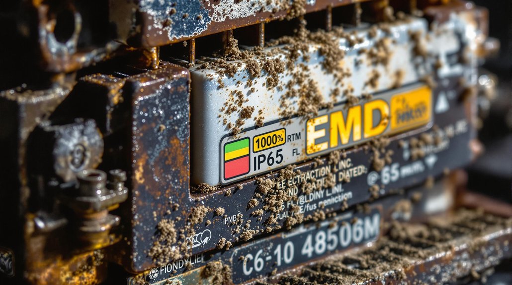
Since EMD locomotives operate across diverse climatic zones—from arctic freight corridors to desert mining operations—your diode selection must account for environmental stresses that can dramatically exceed laboratory test conditions. You’ll need IP65-rated enclosures minimum to prevent moisture ingress and dust accumulation that compromises electrical performance.
| Environmental Factor | Required Specification |
|---|---|
| Temperature Range | -40°C to +100°C continuous |
| Humidity Tolerance | 95% RH non-condensing |
| Vibration Resistance | IEC 61373 Cat 1 Class B |
Material compatibility becomes critical when selecting lead-free grades like MY258A2, which must withstand chemical exposure from lubricants and coolants without degradation. Your diodes must demonstrate <1% power loss drift over 10,000+ operating hours to guarantee diode longevity.
Accelerated aging tests simulating freeze-thaw cycles, UV exposure, and saltwater corrosion help predict real-world performance. Proper cooling systems are essential to prevent overheating during rectifier operation, as excessive temperatures can lead to premature diode failure and reduced conversion efficiency. Prioritize components meeting EN 50155 railway standards to minimize environmental impact while maintaining reliability across extreme operating conditions.
Vendor Selection and Compliance With Railway Industry Standards

You must verify that your chosen vendor demonstrates proven compliance with EN 50328 and IEC 60146 standards through documented type testing and certification records. Evaluate the manufacturer’s track record in supplying rectifier diodes specifically for EMD traction systems, ensuring they maintain AAR/RIA qualifications and can provide transparent material traceability documentation. Your vendor assessment should prioritize suppliers who offer extensive technical support for EMD AR10 alternator integration and can guarantee consistent production quality through EN-standardized verification processes.
Railway Standards Compliance
When specifying EMD traction rectifier diodes, adherence to established railway industry standards guarantees operational safety, system interoperability, and regulatory compliance across diverse transit applications. Modern rectifier technology must navigate complex compliance challenges while maintaining performance specifications.
Critical standards governing your selection include:
- IEEE Std 1653.2-2020 – Defines design parameters for uncontrolled rectifiers up to 1500 V DC, establishing manufacturing and testing protocols
- EN 50328 – European standard mandating performance criteria, safety protocols, and reliability benchmarks for traction rectifiers
- IEC 60146-6 – Specifies operational parameters including voltage tolerance thresholds and thermal management requirements
- NEMA RI-9 – Provides guidelines for overload capacity ratings and service classifications
You’ll need third-party certification audits for high-voltage applications, thorough documentation packages, and conformance testing verification to ascertain your diode selections meet regulatory requirements.
Qualified Vendor Assessment
Qualified vendors must demonstrate thorough compliance with railway industry standards before you can consider their EMD traction rectifier diodes for critical applications. Your vendor evaluation process should verify RISQS prequalification status, guaranteeing suppliers meet health & safety requirements and ISO 9001 quality management standards. For North American operations, confirm AAR certification through their rigorous approval process including design submissions and facility assessments.
Examine supplier reliability through documented safety cases compliant with CENELEC EN50126/29 standards and IEC 61508 functional safety requirements. Review certification evidence including test reports and conformity statements for electrical systems. Validate that vendors maintain current ISA assessments from accredited bodies like Ricardo or TUV SUD. Ascertain suppliers demonstrate proactive risk management and establish continuous monitoring processes for design changes, maintaining traceability throughout their qualification lifecycle.
Frequently Asked Questions
What Diagnostic Features Help Identify Failing Rectifier Diodes in EMD Locomotives?
Detecting defective diodes demands decisive diagnostic tools for accurate analysis. You’ll monitor voltage imbalances exceeding 25,000V limits through continuous tracking systems. Thermal sensors flag “hot diode” faults triggering alarm modes, while Hall-effect current transducers provide galvanic isolation during diode testing procedures. Fault code displays specify diode-related failures with operational restrictions. Historical logging stores recurring failure data, enabling mathematical analysis of thermal management patterns and voltage spike correlations for precise maintenance scheduling.
How Do You Match Diodes for Current Sharing in Parallel Configurations?
You’ll achieve ideal current distribution in parallel operation by selecting diodes from identical production lots with matched forward voltage characteristics within ±2% tolerance. Implement equal series resistance (1-3Ω) for each branch to compensate Vf mismatches. Mount diodes on shared thermal substrates with symmetrical PCB trace lengths to minimize parasitic resistance disparities. Pre-test IV curves to verify consistency and guarantee uniform thermal coefficients for stable current sharing performance.
What Fusing Strategies Work Best for Individual Versus Common Protection Schemes?
Choosing fusing strategies is like threading a needle—precision matters. You’ll find individual protection excels when you need selective isolation and fault localization in multi-bridge systems, preventing cascading failures across parallel rectifier paths. Common protection simplifies maintenance while centralizing load management, though you sacrifice granular control. For 12-pulse traction systems, individual fusing typically outperforms common schemes by enabling targeted diagnostics and maintaining √3 winding balance during fault conditions.
How Does PWM Switching Frequency Affect Rectifier Diode Selection and Losses?
PWM impact on rectifier selection escalates exponentially with frequency. You’ll encounter reverse recovery losses proportional to fsw×Q, where stored charge becomes critical above 50kHz. Diode efficiency degrades through junction capacitance charging cycles and increased I²R losses from peak currents. You must prioritize Schottky diodes for frequencies exceeding 100kHz, or shift to SiC technology above 500kHz to maintain acceptable loss ratios below 2-3%.
What Thermal Interface Materials Optimize Heat Transfer in Traction Rectifier Assemblies?
You’d think slapping any thermal pad onto rectifier diodes would suffice—until junction temperatures soar beyond ratings. For traction assemblies, you’ll need silicone pads delivering 4.9 W/mK thermal conductivity, ensuring efficient heat transfer from semiconductor junctions to heat sinks. Phase change materials optimize interface bonding by conforming to surface irregularities under operational temperatures. Select materials meeting rail industry thermal cycling standards for reliable performance.
You may also like to read – EMD Locomotive Specification Book SD40-SPEC8054-31DEC65