
Railway maintenance professionals face enormous pressure managing complex dynamic braking systems reliably. Grid box failures cause expensive unplanned downtime, safety compliance issues, and operational disruptions. Many technicians struggle identifying authentic OEM components, understanding proper assembly procedures, and maintaining critical thermal systems. Without comprehensive knowledge of grid box architecture, procurement specialists waste resources sourcing incompatible parts. This guide eliminates confusion and empowers you with professional-grade technical knowledge for confident maintenance and sourcing decisions.
Key Challenges Locomotive Owners Facing:
- Grid box component failures cause unexpected downtime and derail tight schedules
- Sourcing authentic, compatible parts from unreliable suppliers creates procurement headaches
- Thermal management failures result in catastrophic equipment damage and safety risks
- Electromagnetic interference disrupts sensitive railway signaling and communication systems
- Maintenance personnel lack clear understanding of proper assembly and inspection procedures
- Incorrect component specifications waste budget resources and compromise performance
- Temperature monitoring failures allow dangerous overheating conditions to develop undetected
- Aging locomotive fleets require specialized knowledge of legacy system configurations
- Parts compatibility issues between different locomotive manufacturers create sourcing complications
- Lack of standardized maintenance protocols increases maintenance costs and extends repair timelines
Understanding the Locomotive Grid Box: Core Architecture
The locomotive grid box represents one of the most critical thermal management systems in modern freight operations. This sophisticated assembly converts kinetic energy from braking into manageable heat through carefully engineered resistor networks. Understanding the fundamental architecture ensures proper maintenance, accurate component sourcing, and reliable operational performance.
The diesel-electric locomotive employs dynamic braking technology that fundamentally differs from conventional friction-based systems. When operators engage the dynamic brake controller, traction motors transition from propulsion mode to electrical generation mode. This conversion creates substantial electrical current requiring immediate dissipation through the grid box resistor assembly. Without proper heat dissipation technology, dangerous voltage buildup would damage sensitive electrical components and create hazardous operating conditions.
Primary Component Structure
| Component | Function | Materials | Criticality |
|---|---|---|---|
| Frame Structure | Mechanical support foundation | Galvanized/stainless steel | Critical |
| Resistor Banks | Primary heat generation | Iron-chromium-aluminum alloy | Critical |
| Blower Motor | Forced air cooling delivery | Copper windings, steel housing | Critical |
| Terminal Connections | Electrical circuit linkage | Oxygen-free copper | Critical |
| Ceramic Insulators | Electrical isolation | Porcelain/ceramic materials | Critical |
| Temperature Sensors | Thermal monitoring | Thermistor elements | High |
Frame and Mounting Configuration Fundamentals
The frame structure provides the engineering foundation supporting all internal components. This structural hierarchy includes vertical supports, horizontal rails, and transverse cross-members creating rigid geometric alignment. Proper frame design accommodates thermal expansion while maintaining precise component positioning.
Frame Design Requirements
Load Distribution: The frame must support enormous resistor weight and thermal stress. Foundation pads transmit forces directly to locomotive carbody attachment points. Mounting pedestals prevent frame deflection during vibration-induced mechanical stress. Cross-braces maintain dimensional stability across extended operating temperatures.
Airflow Optimization: Precise spacing between frame elements enables high-velocity cooling air circulation. Restricted airflow directly reduces cooling effectiveness and thermal capacity. Frame geometry must permit unimpeded air passage through the entire resistor element assembly. Obstruction-free passages prevent localized heating and catastrophic element failure.
Thermal Accommodation: Resistor elements expand significantly during intensive braking operations. Frame design incorporates flexible mounting that allows dimensional changes without creating binding stress. Expansion accommodation prevents warping, cracking, or mechanical failure under thermal cycling.
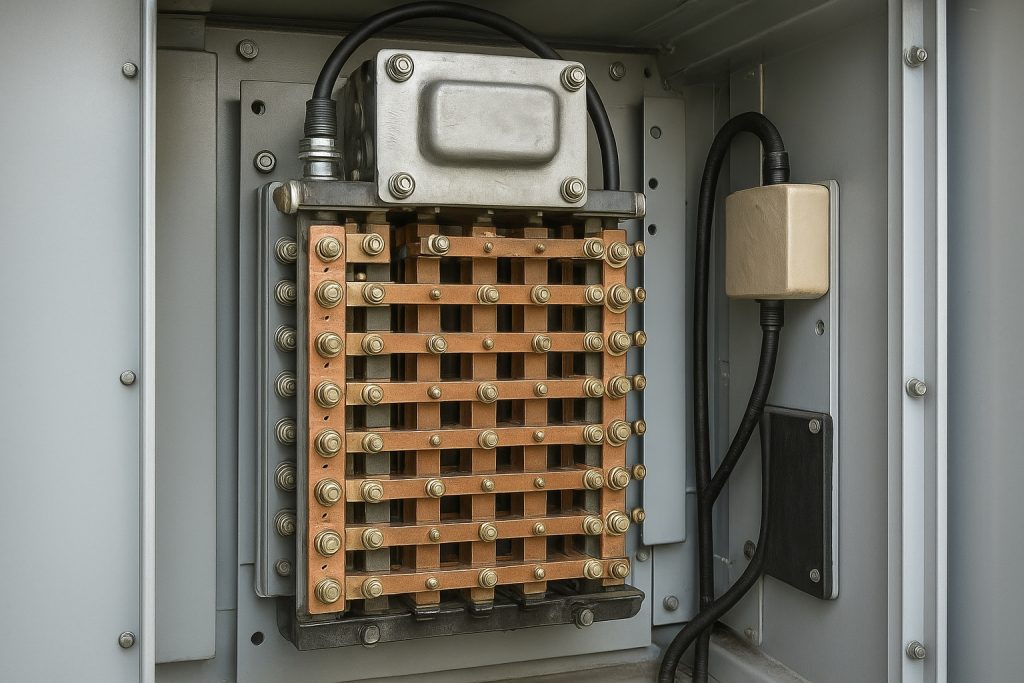
Resistor Elements: Electrical Configuration and Arrangement
The resistor elements and grid arrangements represent the fundamental heat-generation mechanism. These specialized components convert electrical current into thermal energy through precisely calculated resistance values. Modern designs employ stainless steel alloy grid resistors mounted on ceramic insulators within the frame structure.
Resistor Element Configuration Matrix
| Configuration Type | Arrangement | Application | Advantages |
|---|---|---|---|
| Series Connection | Single current path | Low-power operations | Simplified control |
| Parallel Connection | Multiple current paths | High-power braking | Reduced voltage drop |
| Series-Parallel Mix | Segmented groupings | Most freight locomotives | Operator control flexibility |
| Serpentine Pattern | Alternating current direction | EMI reduction critical systems | Electromagnetic shielding |
Serpentine Arrangement Advantages: This sophisticated configuration forces electrical current through adjacent resistor paths in opposite directions. Current alternation significantly reduces electromagnetic field emanations that would otherwise disrupt railway signaling infrastructure. Heat distribution optimizes across the entire resistor network. This arrangement represents standard practice on modern freight and passenger locomotives operating near sensitive communications equipment.
Grid Resistor Material Specifications
Resistor elements utilize high-alloy stainless steel compositions—typically 1.4841 or 1.4541 standards—specifically selected for extreme temperature stability. These materials maintain consistent electrical properties even when element surfaces reach 600+ degrees Celsius during intensive braking. Traditional carbon alloy resistors proved unsuitable for modern applications due to unpredictable electrical drift during thermal cycling. High-alloy materials provide reliable, repeatable performance across millions of operational cycles.
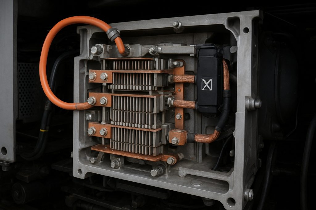
Thermal Management: The Forced Air Cooling System

Forced air cooling systems represent the engineering backbone enabling reliable grid box operation. Without forced ventilation, resistor elements would reach dangerous temperatures causing catastrophic failure within minutes of intensive braking application. Modern grid blowers compress enormous air volumes at high velocity through the resistor element assembly.
Grid Blower Fan System Architecture
The grid blower comprises an electric motor driving a substantial centrifugal fan assembly. These motors typically receive auxiliary electrical power through sophisticated control algorithms monitoring real-time grid temperature. Modern systems automatically modulate blower speed proportional to grid heating intensity. This elegant self-regulating design ensures adequate cooling capacity under all operating conditions.
Self-Regulating Power Supply: One resistor element provides a special motor tap connection supplying blower motor power. As overall grid activity increases, voltage elevated across resistor tap connections automatically increases. This design ensures cooling capacity automatically scales with heat generation—no additional control logic required.
Temperature-Based Blower Control: Modern locomotives incorporate sophisticated temperature monitoring systems continuously assessing grid thermal status. Thermal sensors strategically positioned within the grid assembly provide real-time temperature feedback. When temperatures approach critical thresholds (typically 650-700°C), the control system automatically reduces or disconnects dynamic braking application. This protective mechanism prevents catastrophic element damage and maintains operational safety.
Electrical Connectivity and Terminal Design
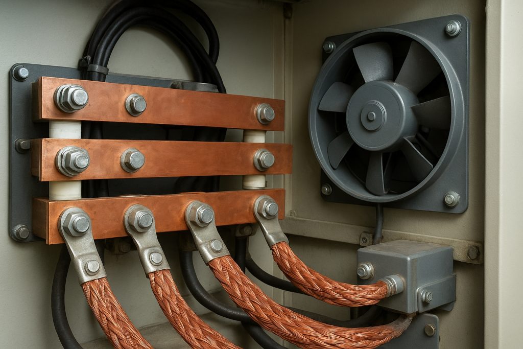
Electrical terminal connections and conductor lugs must safely carry extraordinary electrical currents—often exceeding several hundred amperes at 600-1500 volts. These specialized components represent the interface between traction motor circuits and grid box resistor elements. Standard electrical connectors prove completely inadequate for such extreme current requirements.
Terminal Connection Specifications
Terminal assemblies employ oversized threaded studs fabricated from oxygen-free copper or superior copper alloys. These terminals support bolted connections to comparably oversized conductor strips routed to traction motor circuits. Terminal mountings utilize ceramic standoff insulators maintaining electrical isolation from conductive frame structures.
Current Path Optimization: The electrical path through grid elements undergoes careful engineering to achieve multiple objectives simultaneously. Serpentine current routing minimizes electromagnetic interference while optimizing heat distribution. Current-carrying conductors follow configurations minimizing loop areas and reducing electromagnetic field generation. Braided shield conductors provide additional electromagnetic shielding in critical applications.
Operator-Controlled Braking Intensity: Electrical configuration accommodates precise operator braking control through dynamic brake controller selections. Lower braking intensity settings energize only partial resistor grids. Higher settings progressively engage additional grids creating stepped braking power increases. This approach provides operators fine-grained retarding force control—essential for precise speed management on complex railway grades.
Insulation Systems: Multi-Layer Electrical Protection
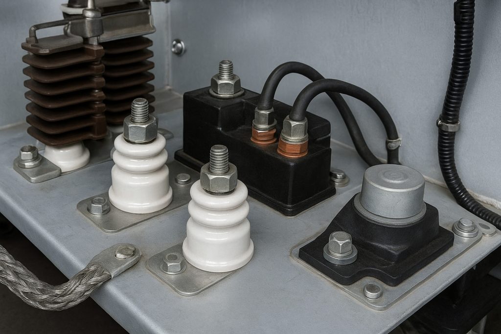
Insulation materials and ceramic insulators provide critical electrical safety protecting personnel and equipment. The insulation architecture employs multiple redundant systems operating at different levels using different materials and principles.
Primary Insulation Elements
Ceramic and porcelain insulators offer superior electrical and thermal stability compared to conventional organic materials. Individual resistor elements mount on ceramic standoffs maintaining precise spacing from conductive frame structures. These insulators prevent electrical breakdown between energized elements and grounded structural components. Operating locomotive electrical testing immediately following maintenance verifies insulation integrity meets design specifications.
High-Potential Testing Standards: Standard specifications require grid box assemblies withstanding 3,200 volts alternating current at 60 Hz for one minute. This stringent testing confirms insulation integrity hasn’t been compromised during assembly or installation. Modern diagnostic procedures employ sophisticated electrical testing equipment confirming insulation meets original equipment manufacturer specifications.
Vibration Isolation and Mechanical Support
Modern grid box designs incorporate elastomeric vibration isolation materials positioned between frame structure and locomotive carbody attachment points. These materials dampen vibration transmission while maintaining electrical isolation. Mounting hardware employs stainless steel fasteners and thread-locking compounds preventing loosening from locomotive vibration.
Protective Features and Environmental Durability
Railway locomotives operate in extraordinarily demanding environments. Salt spray exposure, moisture infiltration, diesel exhaust particulates, and industrial pollution progressively degrade unprotected materials. Modern grid box designs incorporate sophisticated protective features extending service life.
Cinder Guard and Protective Cover Design
Protective covers enclose resistor element assemblies preventing hot cinder and ember infiltration from locomotive engine exhaust. These guards also shield maintenance personnel from contact with hot elements during post-braking operations. Perforated steel or expanded metal construction permits adequate cooling airflow while providing physical protection. Careful engineering balances competing objectives—sufficient air permeability versus robust physical protection.
Corrosion Prevention Strategies
Resistor Element Alloys: Iron-chromium-aluminum and nickel-chromium compositions provide inherent corrosion resistance superior to ordinary steel. Frame structures employ galvanization or stainless steel construction. Terminal connections receive regular corrosion-inhibiting compound treatments. Modern designs increasingly feature hermetically sealed enclosures with forced ventilation systems managing thermal loads.
Modern Advanced Features and Innovations
Contemporary grid box designs incorporate sophisticated features addressing operational challenges and improving reliability.
Electromagnetic Interference Reduction Technologies
Railway signaling compatibility represents a critical design consideration. Early dynamic braking systems occasionally created anomalies in lineside signals and communications equipment. Serpentine current path arrangement reduces electromagnetic interference significantly. Shielded conductor routing surrounds current-carrying conductors with conductive shielding grounded to locomotive frame. Some advanced designs incorporate ferrite cores wound around power conductors absorbing electromagnetic energy at frequencies most likely to interfere with signaling systems.
Modular Element Replacement Architecture
Modern grid boxes increasingly feature modular construction simplifying component replacement. Rather than requiring entire grid assembly replacement when individual elements fail, modern designs enable individual module replacement. Resistor elements group into easily removable cartridges with quick-disconnect electrical connections. Failed modules extract and replace rapidly without disturbing other components.
Power Dissipation Performance Specifications
Power ratings vary considerably depending on locomotive type and intended service application. Understanding these specifications enables proper equipment selection and maintenance planning.
Typical Power Rating Ranges
Modern freight locomotives incorporate grid boxes rated for continuous power dissipation ranging from 500-700 kilowatts. Heavy-haul specialized designs may exceed 1,000 kilowatts. These ratings represent thermal capacity of resistor element assembly and supporting cooling infrastructure.
Duty Cycle Specifications: Rating specifications indicate sustainable power levels for different application durations. A typical specification might indicate 600 kilowatts continuous, 800 kilowatts for 30-minute intervals, or 1,000 kilowatts for 5-minute intervals. Extended cooling periods are required between intensive braking applications. Specification mismatches between locomotive type and intended service cause rapid deterioration.
Maintenance and Diagnostic Procedures

Comprehensive maintenance protocols ensure grid box reliability and extend component service life.
Visual Inspection Procedures
Initial maintenance stages involve careful visual assessment detecting obvious physical damage. Technicians examine protective covers and cinder guards for impact damage or missing sections. Terminal connections receive inspection for corrosion, discoloration, or arcing evidence. Frame structures are visually assessed for cracks, warping, or stress indicators.
Resistor Element Assessment: Pristine resistor elements exhibit consistent metallic appearance. Elements experiencing excessive thermal stress display characteristic blue, purple, or dark brown discoloration patterns. Severe thermal stress causes element warping or deformation restricting cooling air passage. Black or heavily charred areas indicate localized arc damage requiring immediate replacement.
Electrical Testing and Performance Verification
| Testing Method | Purpose | Acceptable Range | Frequency |
|---|---|---|---|
| Insulation Resistance Testing | Verify electrical isolation integrity | > 10 megohms @ 1000V DC | After major service |
| Resistance Measurement | Confirm element resistance values | Per OEM specifications | During overhaul |
| High-Potential Testing | Confirm insulation breakdown protection | Pass 3,200V AC for 60 seconds | After installation |
| Thermal Imaging | Identify localized heating patterns | Uniform temperature distribution | Quarterly |
Practical Maintenance Tips and Expert Insights
Railway maintenance professionals achieve maximum grid box reliability through disciplined maintenance practices.
Preventive Approach: Regular inspection schedules identifying minor issues before catastrophic failure occurs. Thermal sensors should receive calibration verification annually. Cooling blower performance testing validates adequate air circulation. Terminal connections need corrosion assessment each maintenance cycle.
Component Sourcing Excellence: Authentic OEM-equivalent components ensure proper fit and reliable performance. Mismatched components create electrical incompatibilities and premature failures. Established suppliers providing complete technical support ensure installation competence. Documentation verification confirms component authenticity and compatibility with specific locomotive models.
Conclusion: Optimized Grid Box Performance Strategy
Understanding locomotive grid box components and arrangement empowers maintenance professionals to make informed equipment decisions. This comprehensive architectural knowledge enables accurate problem diagnosis, confident component sourcing, and reliable maintenance execution.
Professional-grade grid box maintenance requires attention to multiple systems simultaneously—thermal management, electrical connectivity, insulation integrity, and protective features. Modern locomotives demand sophisticated understanding of electromagnetic interference mitigation and advanced control systems. Procurement specialists choosing authentic components from trusted suppliers like Mikura International ensure compatibility, reliability, and manufacturer support.
The future of locomotive maintenance excellence depends on comprehensive system understanding and disciplined maintenance execution. Invest in proper training, authentic components, and proven diagnostic procedures—your operational reliability and maintenance budget will reflect these investments.