5 Signs Your EMD Locomotive Alternator Diodes Failed

5 Signs Your EMD Locomotive Alternator Diodes Failed

You’ll notice five key signs when your EMD locomotive’s alternator diodes fail: voltage spikes reaching 20V with excessive AC ripple contaminating sensor signals, grinding or whining noises from the alternator assembly with thermal hotspots, transmission systems entering limp mode due to corrupted control circuits, unbalanced rectification causing voltage drops during acceleration cycles, and erratic auxiliary equipment operation with dashboard warning lights. These electrical signatures create cascading failures throughout your locomotive’s systems, and understanding each symptom’s root cause will help you diagnose problems before they escalate into costly repairs.

Key Takeaways

  • Voltage spikes exceeding 20V and unstable alternator output with excessive AC ripple contamination in sensor waveforms
  • Grinding, whining, or growling noises from alternator assembly with increased vibration and thermal hotspots around housing
  • Transmission entering limp mode and traction motor controllers receiving corrupted signals affecting locomotive responsiveness
  • Unbalanced rectification causing voltage drops during acceleration and reduced efficiency under heavy electrical loads
  • Dashboard warning lights for charging system faults with erratic auxiliary equipment operation and fluctuating gauge readings

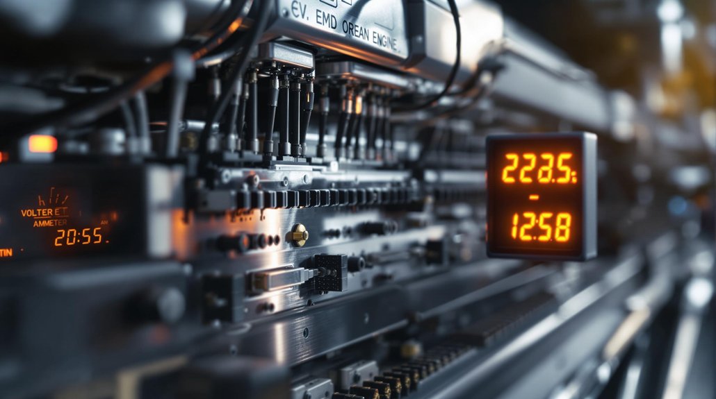
Electrical System Voltage and Current Irregularities

alternator diode failure symptoms

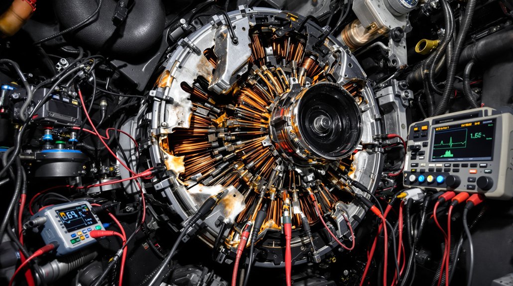
When EMD locomotive alternator diodes begin failing, you’ll notice immediate voltage and current irregularities that compromise your electrical system’s stability. You’ll observe voltage spikes reaching 20V when diodes fail in the bridge configuration, creating dangerous fluctuations that damage sensitive components. The alternator’s output becomes unstable without properly functioning avalanche diodes, preventing consistent AC to DC conversion.

Failed diodes allow excessive AC ripple contamination in your DC circuits, appearing in sensor voltage waveforms and creating interference throughout the electrical system. You’ll detect uneven current distribution across the system when one or more diodes fail, causing amperage output to vary unpredictably with engine speed.

Check for loose connections or damaged wiring that contribute to voltage irregularities. Forward voltage drop increases in degraded diodes, reducing current flow efficiency. Your electrical energy conversion efficiency drops markedly, making proper diode bridge operation critical for maintaining stable locomotive performance. Professional diagnosis using specialized diagnostic tools can accurately identify which specific diodes have failed in the alternator assembly.

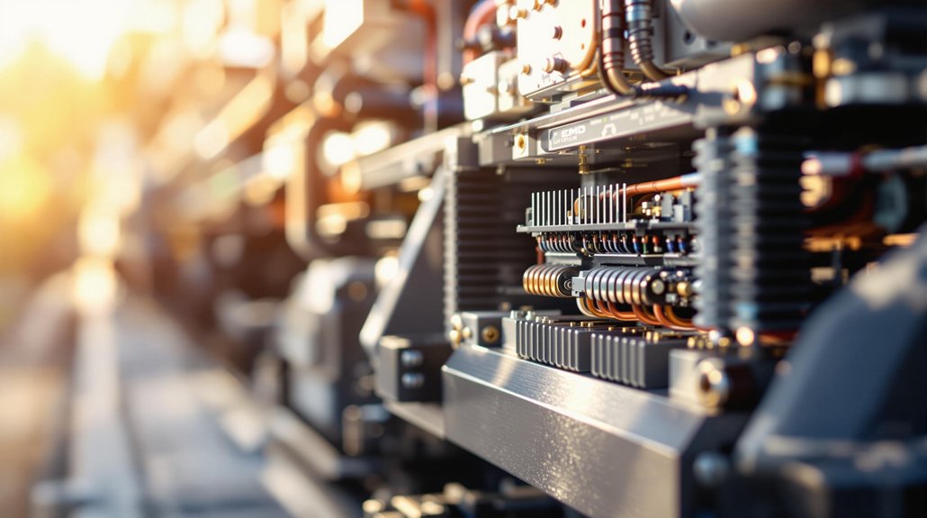
Unusual Noises and Overheating From the Alternator Assembly

diode induced alternator overheating and noise

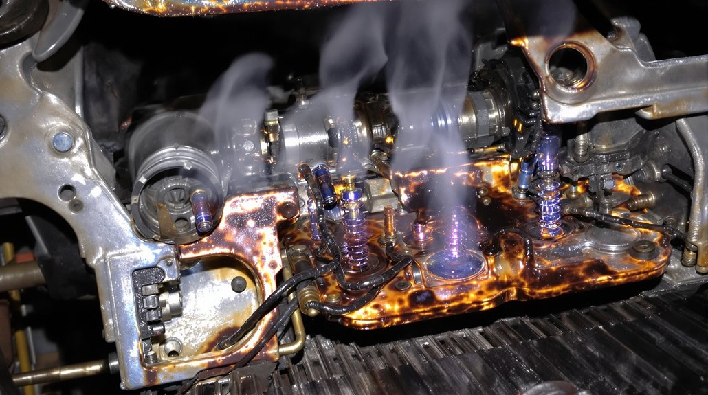
Failed alternator diodes kick off a cascade of mechanical and thermal problems that you’ll hear and feel long before complete system failure occurs. You’ll notice grinding and high-pitched whining noises from the alternator assembly as internal components wear under electrical stress. Growling sounds persist when diodes malfunction, creating system imbalances that intensify under load conditions.

Overheating becomes your primary thermal concern as failed diodes force excessive current flow through remaining components. You’ll detect thermal hotspots around the alternator housing when diodes can’t properly convert AC to DC. Bearing failure compounds these issues, generating distinctive noise patterns while alternator vibration increases due to unbalanced electrical loads.

Multiple shorted diodes create more severe conditions than single failures. You’ll hear different sound characteristics as remaining diodes become overloaded. Monitor your cooling system closely—proper ventilation becomes critical when diode failures reduce efficiency and spike heat production throughout the alternator assembly. Failed diodes also produce electrical ripple that can interfere with sensitive electronic sensors throughout the locomotive’s control systems.

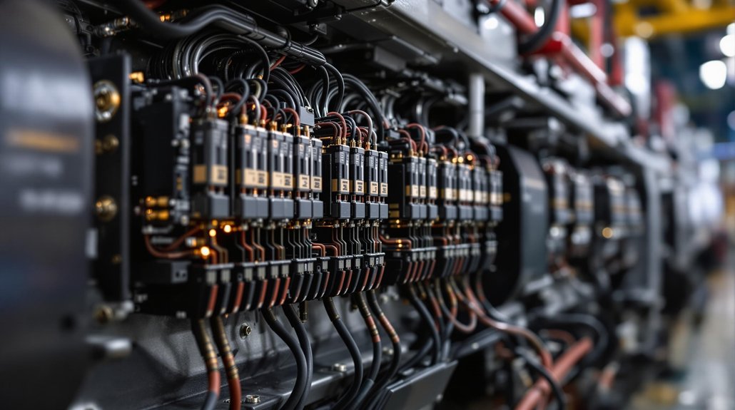
Control System Malfunctions and Transmission Problems

alternator diode induced electrical ripple

Control system electronics become vulnerable targets once alternator diode failures introduce AC ripple into your locomotive’s electrical network. You’ll notice transmission systems entering gearbox limp mode when electrical interference corrupts control circuits. Speed sensors generate false readings due to AC ripple, creating sensor corruption that affects positioning data and wheel slip detection accuracy.

Your electronic control units face immediate risk from shorted diodes that reflect high voltage ripple throughout electrical systems. Traction motor controllers receive corrupted command signals, making acceleration and deceleration responses unreliable. Dynamic braking systems malfunction when diode failures disrupt regenerative power conversion circuits.

Digital communication networks experience data corruption from electrical interference. CAN bus systems become unreliable, and diagnostic communications fail when AC ripple affects low-voltage circuits. Power management systems generate false alarms due to voltage irregularities, while electronic governors malfunction from voltage fluctuations in sensor power supplies. The voltage regulator struggles to maintain stable output voltage within the desired range when diode failures compromise the rectification process.

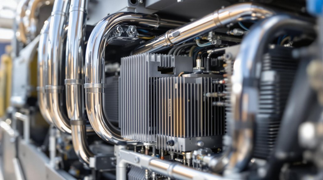
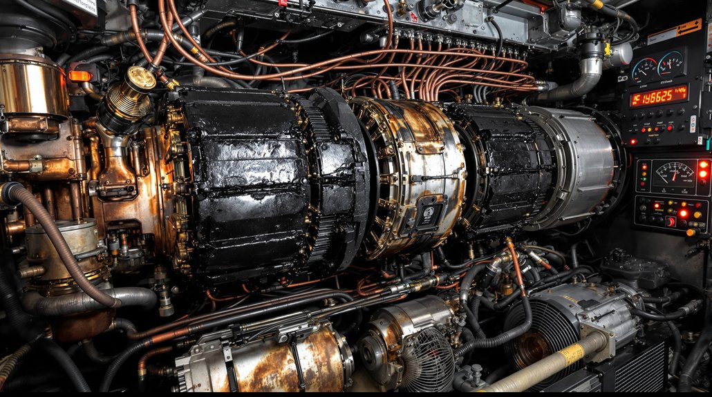
Generator Performance Degradation and Voltage Regulation Failures

alternator diode failure effects

As alternator diodes deteriorate, your locomotive’s generator loses its ability to maintain stable DC voltage output across varying load conditions. Failed diodes create unbalanced rectification that compromises voltage regulation during high-demand operations, directly affecting your traction motor performance and overall locomotive efficiency.

You’ll notice these critical performance indicators when diode failures occur:

  1. Voltage drops during acceleration cycles – Poor load regulation causes insufficient power delivery when you need maximum traction
  2. Reduced efficiency under heavy loads – Generator output capacity decreases markedly, limiting your locomotive’s hauling capability
  3. Unstable charging system performance – Battery charging becomes inconsistent, affecting electrical system reliability

Diode bridge failures also compromise ripple mitigation, allowing excessive AC content to contaminate your DC power supply. This creates electromagnetic interference with control systems and sensors. When multiple diodes fail, you’ll experience dramatically reduced efficiency and may need complete alternator replacement to restore proper generator performance. Since diodes are responsible for converting the generator’s AC output into usable DC power, their failure prevents alternator operation entirely in severe cases.

Secondary Equipment Failures and Dashboard Warning Indicators

alternator diode failure cascade

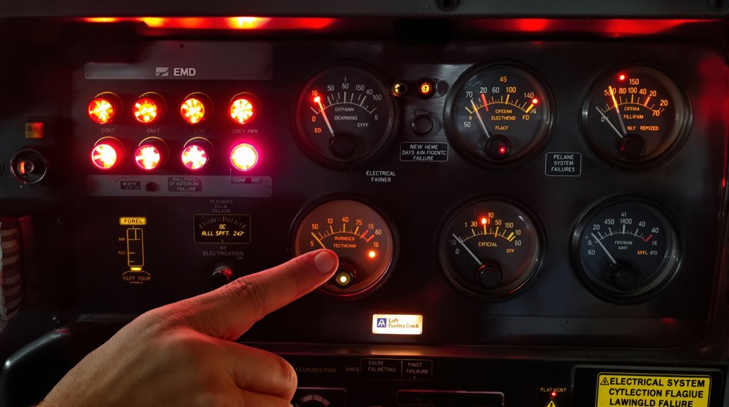
When alternator diode failures cascade through your EMD locomotive’s electrical system, secondary equipment begins malfunctioning in predictable patterns that you’ll recognize through specific dashboard indicators. You’ll notice auxiliary load systems experiencing erratic operation as voltage regulation becomes unstable. Battery charging circuits struggle to maintain proper levels, triggering low battery warnings on your control panel.

Indicator illumination patterns reveal the progression of diode failure. Your ammeter will show irregular charging rates, while voltage gauges display fluctuating readings that deviate from normal operating parameters. Engine cooling fans may cycle unpredictably due to inconsistent power delivery, and lighting systems often dim or flicker intermittently. A portable oscilloscope can reveal diode faults through distinctive ripple patterns in the electrical output.

Critical dashboard warnings include alternator fault lights, charging system alerts, and battery discharge indicators. You’ll observe that auxiliary systems like air compressors and dynamic brake grids respond sluggishly or fail to engage properly. These secondary failures create a diagnostic trail that helps pinpoint diode degradation before complete alternator failure occurs.

Frequently Asked Questions

How Much Does It Cost to Replace Failed Alternator Diodes in EMD Locomotives?

You’ll face $300-$1,200 in total replacement costs for EMD locomotive alternator diodes, depending on your specific model requirements. Labor costs range substantially based on facility capabilities and testing procedures needed. Complete rectifier assembly replacement includes new bus bars, diodes, and fuses rather than individual components. Consider upgraded components with extended parts warranty coverage, as they’ll reduce future failure rates and provide 12+ year service life versus standard 10-year intervals.

Can You Temporarily Operate a Locomotive With One or Two Failed Diodes?

You can temporarily operate with one failed diode under light loads, but you’ll experience reduced charging capacity and uneven output that stresses remaining components. Two failed diodes create dangerous conditions with excessive excitation current that’ll likely damage your exciter rotor within seconds. You must immediately reduce load and head for repairs – don’t risk progressive failures that’ll cascade through your voltage regulator and electrical system.

What Tools Are Needed to Properly Diagnose Alternator Diode Failures?

You’ll need a digital multimeter with diode test function, AC/DC voltmeter, and continuity tester for basic diagnosis. Add an insulation tester to check diode isolation from ground and housing. A thermal imager identifies overheating diodes under load conditions. Use specialized alternator diode testers with rheostat controls for thorough testing. Include insulated test probes, proper disconnection tools, and cleaning materials for accurate measurements and safe electrical work.

How Long Do EMD Locomotive Alternator Diodes Typically Last Before Failing?

Coincidentally, your EMD locomotive alternator diodes typically last 20,000 to 120,000 hours depending on insulation class and operating conditions. You’ll find Class H systems at 180°C achieve roughly 2.3 years, while Class F systems at 155°C extend service intervals to 13.7 years. Environmental factors like excessive heat, poor ventilation, voltage fluctuations, and contamination markedly reduce lifespan, making regular monitoring essential for peak performance.

Should Locomotive Operators Attempt Field Repairs of Failed Alternator Diodes?

You shouldn’t attempt field repairs of failed alternator diodes. These repairs pose significant safety risks including electrical shock and cascading system damage. Field modifications will void your locomotive’s warranty and violate manufacturer specifications. Diode replacement requires specialized training in high-voltage AC/DC conversion systems, professional diagnostic equipment, and knowledge of excitation circuits. Instead, contact certified EMD technicians who possess proper tools and expertise for safe repairs.

Why Do Diesel-Electric Locomotives Need Heavy-Duty Rectifiers?

Why Do Diesel-Electric Locomotives Need Heavy-Duty Rectifiers?

You’ll need heavy-duty rectifiers in diesel-electric locomotives because they convert the main alternator’s three-phase AC output into stable DC power for your traction motors. These robust systems handle continuous electrical loads exceeding 3,000 amperes while withstanding extreme temperatures from -40°F to 185°F and severe mechanical vibrations. They enable precise speed and torque control across multiple motors simultaneously, ensuring consistent power delivery during dynamic load changes. Understanding their complete integration reveals why they’re absolutely critical for locomotive performance.

Key Takeaways

  • Rectifiers convert the alternator’s three-phase AC output to stable DC power required for precise traction motor control and operation.
  • Locomotives demand continuous power conversion up to 3,000 kW with currents exceeding 3,000 amperes during peak operational scenarios.
  • Heavy-duty rectifiers withstand extreme temperatures (-40°F to 185°F), vibration loads exceeding 5G, and harsh environmental conditions including diesel exhaust.
  • Rectifiers enable coordinated power distribution to four or six traction motors simultaneously while maintaining consistent torque output around 60,000 lb-ft.
  • Solid-state rectifier technology provides superior reliability and ruggedness compared to mechanical alternatives while supporting advanced electronic control systems.

Converting AC Power to DC for Optimal Traction Motor Control

heavy duty rectified dc traction

Within the heart of every diesel-electric locomotive, the main alternator converts the diesel engine’s rotational energy into three-phase AC power, but this raw electrical output can’t directly control traction motors with the precision modern rail operations demand. You’ll find that heavy-duty rectifiers function as electrical check valves, converting this AC power into pulsating DC through full-wave rectification. This process captures both positive and negative sine wave alternations, eliminating AC’s 60-times-per-second directional reversals.

The resulting DC power provides superior speed and torque control compared to AC systems. You’re able to achieve precise starting torque characteristics essential for heavy freight applications. Modern solid-state rectifiers integrate with synchronous excitation systems and support regenerative braking capabilities, allowing energy recovery during deceleration. These rectifier banks handle extreme electrical stresses while maintaining continuous operation under harsh railway conditions, directly impacting your locomotive’s overall efficiency and performance. The circuit breakers integrated within these systems provide critical protection against electrical overloads that could damage expensive traction motor components.

Managing High-Current Electrical Loads in Railway Operations

high power traction motor management

When you’re operating diesel-electric locomotives, you’ll encounter continuous high-power demands that can reach 3,000 kW, requiring rectifiers capable of handling sustained electrical loads without thermal failure. Your traction motors draw massive current levels that vary constantly based on speed and load conditions, making precise current management critical for preventing motor damage. You’ll need robust multi-motor load distribution systems that can regulate power flow to four or six traction motors simultaneously while maintaining stable performance under extreme operational conditions. The diesel engine’s mechanical energy must be efficiently converted through the alternator to meet these demanding electrical requirements while supporting both propulsion and auxiliary systems.

Continuous High-Power Demands

As diesel-electric locomotives traverse thousands of miles under continuous operation, their rectifier systems must handle sustained high-current electrical loads that can exceed 3,000 amperes during peak performance scenarios. You’ll find these heavy-duty rectifiers processing continuous power conversion from diesel generators rated between 2000-4000 HP throughout extended railway journeys. The constant electrical flow creates significant thermal fatigue within power electronics components, requiring robust cooling systems and advanced materials.

Your locomotive’s rectifier system experiences demanding duty cycling as it alternates between acceleration, grade climbing, and heavy cargo transport. This continuous service generates thermal stress from frequent load variations, making standard rectifiers inadequate. Heavy-duty rectifiers incorporate IGBT modules and SiC power electronics to maintain consistent voltage levels while managing the thermal cycling inherent in railway operations. Modern locomotives integrate digital technologies to enable real-time monitoring of rectifier performance and reduce operational downtime.

Multi-Motor Load Distribution

Beyond sustaining continuous power conversion, heavy-duty rectifiers must efficiently manage the complex distribution of electrical loads across multiple traction motors that can draw up to 4,700 amperes collectively. You’re dealing with sophisticated power distribution systems that accommodate varying motor requirements caused by axle imbalance from different driving wheel weights. Your rectifiers coordinate with electronic control systems to maintain consistent total traction torque across all motors, delivering approximately 60,000 lb-ft of combined force.

When operating conditions prevent individual motors from delivering designed output, you’ll need torque redistribution capabilities. Your load regulation systems continuously monitor real-time demands, adjusting generator output while preventing wheel slip through precise power delivery modulation. The compression ignition diesel engine provides the reliable mechanical energy foundation that powers the entire electrical generation system. Advanced predictive algorithms enable preemptive load distribution adjustments, maximizing fuel efficiency by matching generator output to actual distributed power needs across multiple coordinated traction motors.

Solid-State Rectification Technology for Enhanced Performance

solid state alternator rectifier technology

Since EMD’s introduction of the AR10 Alternator Rectifier system in 1966, solid-state silicon diode technology has revolutionized locomotive power conversion by delivering superior performance characteristics that mechanical systems couldn’t match. You’ll find that silicon reliability guarantees consistent operation despite harsh vibrations and temperature extremes encountered in locomotive environments. The diode ruggedness withstands demanding operational conditions while maintaining voltage drops of only fractions of a volt through the rectifier.

You’re benefiting from full-wave rectification that converts AC sine waves to pulsating DC, enabling precise motor speed and torque control. The technology eliminates shifting requirements, improving overall system reliability while providing faster response times than mechanical switching. External mounting on traction alternators gives you accessible maintenance access, reducing downtime.

Modern rectifiers expand alternator output capacity beyond previous limitations, delivering consistent power regardless of engine speed variations. You’ll experience optimized efficiency through advanced electronic control systems that regulate power flow across varying operational demands. Heavy-duty rectifiers handle the substantial current loads required by DC traction motors that provide the high starting torque essential for locomotive operation.

Strategic Placement and Physical Integration Within Locomotive Systems

rectifiers integrated within locomotive systems

You’ll find rectifiers strategically positioned in auxiliary cab sections where they’re protected from operational hazards while maintaining ideal access to high-voltage distribution networks. The placement directly influences high-voltage cable routing efficiency, as shorter runs between alternators and traction motors reduce power losses and improve system response times. Your locomotive’s cooling system integration becomes critical at this junction, since rectifier positioning must balance thermal management requirements with the need for environmental protection of sensitive solid-state components. These rectifiers must handle the conversion from AC to DC while managing electrical faults through integrated protective devices that safeguard the entire power distribution system.

Auxiliary Cab Positioning

Strategic placement of auxiliary cab components hinges on achieving peak integration between operator accessibility and system performance requirements. You’ll find NSW signalling standards mandate left hand seating configuration with observer placement on the right side during forward travel. This positioning optimizes your access to angled control stands preferred by operators over European desk-type layouts. You can effectively manage diesel engine controls and electrical systems through this strategic arrangement.

The auxiliary generator’s voltage regulator sits in the upper left corner of equipment cabinets, while electronic controls cluster near the cab for maintenance accessibility. Single cab configurations work in US structure gauge environments, but you’ll need dual control stands for narrow body locomotives requiring bidirectional operation, each oriented for left-hand running.

Modern locomotives utilize hydraulic governance systems alongside electronic controls to ensure optimal engine speed regulation for varying power demands. This integration allows for precise coordination between the auxiliary cab positioning and the engine control mechanisms that maintain appropriate performance levels across different operational scenarios.

High-Voltage Cable Routing

Mapping out high-voltage cable pathways demands precise coordination between electrical safety requirements and mechanical constraints within locomotive systems. You’ll need to establish dedicated conduit segregation for 2000V maximum power leads, keeping them isolated from auxiliary circuits to prevent electromagnetic interference. Your DLO cables require stranded tinned copper conductors with EPR insulation and CPE construction for optimal jacket durability in harsh locomotive environments.

You must route these cables through independent pathways connecting traction motors to rectifier assemblies. The +90°C temperature rating ensures reliable operation in engine compartments, while UL Type RHH/RHW-2 approvals maintain safety compliance. Your cable management system should accommodate both fixed installations and flexible locomotive movement, utilizing organized raceway systems that protect against mechanical damage while maintaining proper voltage separation throughout the entire diesel-electric power distribution network. Modern compact power electronics have simplified the construction requirements for these high-voltage routing systems, reducing space constraints while improving overall reliability.

Cooling System Protection

When rectifier assemblies convert high-voltage AC power to DC within your locomotive’s electrical system, they generate substantial heat that demands strategic cooling integration to prevent thermal failures. Your cooling system must effectively manage temperatures across multiple heat sources while maintaining peak performance.

Critical cooling protection components include:

Coolant routing circuits that connect rectifier assemblies to main radiator networks

  • Thermostat calibration systems that regulate flow based on thermal load requirements
    • Thermal overload sensors monitoring ambient inlet air and component temperatures
    • Water pumps circulating 265-530 gallons through integrated cooling networks
    • Circuit breaker integration preventing electrical overloads that generate excessive heat
  • Your locomotive’s thermal protection calculates traction motor current limits using temperature data, ensuring rectifiers operate within safe parameters while maintaining constant horsepower output during demanding operations. Proper coolant formulations with corrosion inhibitors create protective films that safeguard rectifier housing and heat exchanger metal surfaces from rust and chemical damage.
  • Withstanding Environmental Stresses and Operational Vibrations

rugged high vibration rectifiers

  • Operating in harsh railroad environments, heavy-duty rectifiers must endure extreme temperature fluctuations ranging from -40°F to 185°F while maintaining precise voltage conversion performance. You’ll find these components undergo rigorous environmental qualification protocols that test moisture resistance, dust ingress protection, and thermal cycling endurance. The rectifiers face constant mechanical stress from track irregularities, coupling forces, and engine vibrations that can exceed 5G acceleration loads.
  • Your locomotive’s rectifier assemblies require specialized vibration testing to validate structural integrity under continuous operational stresses. The mounting systems incorporate shock-absorbing materials and reinforced housing designs that prevent component fatigue and electrical connection failures. You’re dealing with power electronics that must function reliably despite exposure to diesel exhaust, corrosive elements, and electromagnetic interference from traction motors. These environmental challenges demand robust semiconductor packaging, conformal coatings, and hermetic sealing techniques that guarantee consistent electrical performance throughout extended service intervals. Modern diesel-electric locomotives have evolved significantly since the early 20th century when various countries first introduced these revolutionary rail vehicles.
  • Maximizing Energy Efficiency Through Advanced Power Conversion

diesel electric locomotive energy optimization

  • Through sophisticated power conversion technologies, diesel-electric locomotives transform raw fuel energy into precisely controlled electrical output with remarkable efficiency gains that you’ll find essential for modern rail operations.
  • Advanced rectifier systems enable diesel-electric locomotives to achieve substantial energy improvements through optimized conversion processes. You’ll benefit from these efficiency-maximizing technologies:
  • Dynamic braking recovery – Captures 12-33% of operational energy through regenerative strategies during deceleration phases

  • Waste heat utilization – Recovers up to 437.6 kW from exhaust gas thermal optimization, representing 18% of maximum engine power

  • Precision power management – Controls timing and delivery of electrical energy to traction motors with minimal conversion losses

  • Advanced rectification – Converts AC to DC electricity while reducing mechanical component wear through efficient power handling

  • Integrated electronics – Adapts power delivery based on operational demands for peak performance across varying conditions
  • These systems deliver $54,000 to $140,000 annual fuel savings per locomotive while maintaining the robust power conversion capabilities essential for heavy-duty rail operations.
  • Supporting Multiple Traction Motors Across Locomotive Configurations

modular redundant traction power

  • Scaling up from single motor operations, diesel-electric locomotives distribute power across multiple traction motors through sophisticated rectifier systems that must handle the full electrical load of the entire propulsion system. You’ll find that heavy-duty rectifier banks process the complete alternator output before distribution, creating modular scalability that adapts to different locomotive configurations. Multiple rectifier units work together, establishing redundant pathways that guarantee reliable power delivery even if individual components fail.
  • Your locomotive’s electrical architecture varies by manufacturer—GM uses one inverter per truck while GE employs one inverter per motor. Each inverter contains six gated turn-on devices and high-power thyristors that manage power flow to individual traction motors. The rectification stage precedes these inverter systems, smoothing uneven alternator output into stable DC power. This coordinated approach eliminates external power supply dependencies while supporting simultaneous motor operation across the entire locomotive fleet.
  • Integration With Modern Electronic Control and Monitoring Systemsintelligent real time rectifier monitoring
  • Modern diesel-electric locomotives integrate sophisticated electronic control systems that continuously monitor and regulate rectifier performance across all operational parameters. These microprocessor-based controllers deliver precise voltage and current regulation while providing real time diagnostics for peak power conversion efficiency.
  • Advanced solid-state rectifier technology incorporates intelligent monitoring capabilities that track critical performance metrics:
  • Temperature monitoring and thermal management across semiconductor components

  • Current load analysis with automatic compensation for varying electrical demands

  • Conversion efficiency tracking with integrated feedback loop adjustments

  • Fault detection algorithms that enable predictive maintenance scheduling

  • Harmonic reduction control through precise switching frequency management

  • You’ll find these control systems automatically adjust rectifier operations during dynamic load changes, ensuring consistent power delivery to traction motors. The integrated diagnostic capabilities detect potential failures before they occur, reducing downtime and maintenance costs. Electronic protection algorithms coordinate with circuit breakers to isolate faults instantly, maintaining system integrity while maximizing locomotive performance under demanding operational conditions.

Frequently Asked Questions

  • How Much Do Heavy-Duty Rectifiers Cost Compared to Standard Electrical Components?
  • Like Hercules bearing Atlas’s burden, you’ll find heavy-duty rectifiers commanding premium pricing over standard components. Your material costs escalate markedly—locomotive rectifiers range $15,000-$45,000 versus $500-$2,000 for standard units. However, your lifecycle pricing analysis reveals compelling economics: heavy-duty systems deliver 20-year operational lifespans with minimal degradation, while standard components require frequent replacement. You’re investing in robust silicon-controlled rectifier technology that withstands extreme thermal cycling and vibration demands.

  • What Happens When a Rectifier Fails During Locomotive Operation?
  • When your rectifier fails, you’ll experience immediate power conversion disruption that cuts DC electricity flow to traction motors. Your locomotive loses consistent power supply, causing reduced mechanical output and potential engine stall. You’ll face irregular voltage distribution throughout electrical systems, leading to axle overheating from uneven power delivery. Complete operational shutdown occurs as your engine control systems can’t manage power timing effectively.

  • How Often Do Heavy-Duty Rectifiers Require Replacement or Major Maintenance?
  • “An ounce of prevention’s worth a pound of cure” applies perfectly to rectifier maintenance. You’ll need diode replacements every 15,000-25,000 hours, while complete module overhauls occur every 50,000-75,000 hours. Service intervals tighten to 500-750 hours under high-amperage conditions. Monitor forward voltage drops and harmonic distortion levels—these failure modes signal imminent replacement needs. Environmental factors reduce standard intervals by 20-30%, demanding vigilant condition-based monitoring.

  • Can Older Locomotives Be Retrofitted With Modern Solid-State Rectifier Systems?
  • You can retrofit older locomotives with modern solid-state rectifier systems, though legacy compatibility requires careful evaluation of existing electrical infrastructure. Installation challenges include adapting mounting configurations, upgrading control systems, and ensuring proper integration with original traction motors. You’ll need to modify wiring harnesses and potentially replace associated power electronics components. These retrofits deliver significant performance improvements, extending locomotive service life by 25 years while achieving substantial efficiency gains.

  • Do Different Locomotive Manufacturers Use Compatible Rectifier Technologies?
  • You’ll find that different locomotive manufacturers don’t use compatible rectifier technologies despite similar functional requirements. While EMD, GE, and other builders all adopted solid-state rectification by the mid-1960s, manufacturer compatibility remains limited due to proprietary designs. Each company developed distinct technology standards for voltage ratings, cooling systems, and control interfaces. You can’t easily interchange rectifier units between EMD and GE locomotives without significant electrical system modifications.

7 High-Voltage Diodes for Railway Rectifier Applications

7 High-Voltage Diodes for Railway Rectifier Applications

You’ll need high-voltage diodes rated for 2,000-2,500A continuous current with voltage specifications ranging from 24V-110V DC to 25kV AC for railway rectifier applications. These diodes must comply with EN 50155 standards and withstand thermal cycling from -40°C to +85°C while maintaining ≤1.2V forward voltage drop. Critical features include surge protection up to 25kA fault current capacity, integration with 6-24 pulse rectifier configurations for harmonic reduction, and real-time monitoring capabilities for locomotive traction systems. Advanced specifications and selection criteria await your consideration.

Key Takeaways

  • High-voltage railway diodes must handle 15kV-25kV AC with current ratings up to 2,000A for traction applications.
  • Forward voltage drop should remain ≤1.2V at rated current to minimize power losses in rectifier circuits.
  • Diodes must comply with EN 50155 standards and withstand 0.7-1.25× nominal voltage ranges for railway certification.
  • Junction temperatures must stay below safety thresholds with thermal cycling from -40°C to +85°C operational ranges.
  • Multi-pulse rectifier configurations (6, 12, or 24-pulse) require matched diode sets for effective harmonic distortion reduction.

Voltage and Current Specifications for Railway Power Systems

railway power system specifications

Railway power systems operate across five distinct voltage categories, each demanding specific diode characteristics to guarantee safe and reliable rectification. You’ll encounter 24V-110V DC for auxiliary systems, 750V-1500V DC for traction networks, and 15kV-25kV AC for overhead transmission lines. Each category requires precise current rating calculations to handle peak operational loads.

For traction applications, you must specify diodes with current ratings up to 2,000A while maintaining minimal voltage drop across the junction. EN 50155 compliance mandates your diodes withstand 0.7-1.25× nominal voltage ranges, with transient tolerance reaching 1.4× for ≤100ms periods. High-voltage substations operating at 72kV require surge-rated diodes exceeding 25kA fault current capacity.

Your rectifier design must account for voltage drop limitations—typically ≤1.2V forward drop at rated current—to maintain system efficiency. Temperature derating factors become critical above 70°C, directly affecting both current rating and voltage drop characteristics under sustained railway operations. Power source transitions frequently cause voltage interruptions where diodes must continue rectification despite momentary drops to 0V for periods up to 20ms.

Thermal Management and Environmental Durability Standards

railway thermal management standards

Meeting precise voltage and current specifications means nothing if your diodes can’t survive the punishing thermal and environmental conditions found in railway operations. You must maintain maximum junction temperature below safety thresholds while managing thermal cycling between -40°C and +85°C operational ranges.

Critical thermal management parameters include:

  1. Thermal resistance (RθJC) quantifying heat transfer from junction to case
  2. ΨJT parameters enabling rapid Tj estimation via case temperature measurements
  3. Temperature differential (ΔT) restricted to ≤10K between ambient and initial junction temperature
  4. Continuous monitoring at ≥1 sample/hour during accelerated aging tests

Environmental durability testing follows IEC 60068-2-67 standards, maintaining 85°C ±2°C with 85% ±5% relative humidity. Advanced thermal management employs phase-change materials and composite structures for enhanced heat dissipation. Dynamic voltage cycling optimizes power loss distribution, while proper heatsink placement determines whether you’ll use RθJC or ΨJT thermal resistance values for system design calculations.

ECPE’s working groups specifically address power semiconductor reliability for railway applications, providing industry consensus on testing protocols and qualification standards. Advanced thermal management employs phase-change materials and composite structures for enhanced heat dissipation. Dynamic voltage cycling optimizes power loss distribution, while proper heatsink placement determines whether you’ll use RθJC or ΨJT thermal resistance values for system design calculations.

Compliance With International Railway Electronics Regulations

railway electronics compliance regulations

You’ll need to navigate three critical regulatory frameworks when implementing high-voltage diodes in railway rectifier systems: EN 50328 standards for railway power supply equipment, IEEE traction power requirements, and IEC certification protocols. These regulations establish mandatory performance thresholds for voltage stability, fault protection, and electromagnetic compatibility that directly impact your diode selection and circuit design decisions. Your compliance strategy must address each framework’s specific testing requirements, as failure to meet any single standard can result in certification rejection and operational safety risks. Railway rectifier systems must also meet EN 50155 requirements for electronic equipment operating conditions, design specifications, and integration protocols to ensure reliable performance across all rail vehicle applications.

EN 50328 Standards

Compliance with EN 50328 establishes the foundation for deploying high-voltage diodes in railway traction power systems, where this European standard specifies mandatory requirements for fixed installations of electronic power converters across railways, tramways, light rail, and underground systems.

Your diode selection must meet stringent performance criteria that directly impact converter efficiency in harsh electrical environments. The standard mandates specific testing protocols for semiconductor devices:

  1. Type testing under simulated traction system stresses
  2. Insulation testing for AC/DC interfaces per Table 8 criteria
  3. Short-circuit protection validation following railway safety standards
  4. Thermal management assessment under variable load conditions

You’ll need to guarantee your high-voltage diodes demonstrate reliability during dynamic load variations typical in accelerating trains, while maintaining voltage stability and meeting the durable semiconductor material requirements specified for railway traction applications. Adherence to established protocols enhances security by ensuring your diode implementations follow proven railway electronics standards.

IEEE Traction Requirements

Beyond EN 50328’s European framework, IEEE standards provide the international backbone for railway traction electronics, with IEEE 16-2020 establishing non-negotiable performance benchmarks that your high-voltage diodes must satisfy across global rail networks. You’ll encounter stringent voltage tolerances requiring precise semiconductor material specifications and manufacturing tolerances that directly impact diode reliability during operation.

Your designs must withstand extensive testing protocols including surge immunity assessments, temperature cycling from -40°C to +70°C, and mechanical stress evaluations. IEEE 2752-2023 mandates dual grounding systems with protective ground resistance below 1Ω, ensuring safe fault current dispersion. Critical survivability specifications include thermal derating rules and high dv/dt handling capabilities to manage transient voltage spikes from catenary systems while maintaining fail-safe redundancy mechanisms. These requirements provide uniform design specifications that enhance safety and reliability across all railway control apparatus implementations.

IEC Certification Protocols

While IEEE standards establish the operational framework, IEC certification protocols form the regulatory cornerstone that validates your high-voltage diodes against international railway safety and performance mandates. IEC testing encompasses thorough validation through IECEE third-party laboratories that replicate operational conditions including thermal cycling from -40°C to 85°C and vibration stress per IEC61373.

Your certification processes must address four critical validation areas:

  1. Safety Integrity Levels (SIL) – Components rated SIL 1-4 based on critical functions
  2. EMC Compliance – Electromagnetic compatibility per EN50121-3-2 standards
  3. Environmental Durability – Thermal management and insulation coordination validation
  4. Documentation Requirements – Complete design parameters, safety margins, and test reports

Mutual recognition agreements streamline cross-border approvals, ensuring your diode modules meet international railway electronics regulations while maintaining operational safety margins. IEC TC 9 develops specialized standards for railway and metropolitan transport systems that directly impact diode certification requirements.

Traction Substation Integration and Performance Requirements

traction substation performance requirements

As railway systems shift from traditional motor-generator sets to modern thyristor-based rectifiers, traction substations must accommodate increasingly complex integration requirements that directly impact system performance and reliability. You’ll need to configure these systems for continuous operation at high currents while maintaining stable DC output across variable load ranges.

ParameterSpecificationCritical Impact
Current Rating2,500A continuousThermal management
THD Compliance<5% at 80% loadPower quality
Power Factor>0.95 laggingGrid efficiency
Overload Capacity150% for 60sPeak acceleration
Voltage Regulation±2% no-load to full-loadSystem stability

Your traction system integration requires careful performance analysis of rectifier configurations—6, 12, or 24-pulse designs distribute harmonic currents effectively. You must guarantee rectifiers handle regenerative braking energy while maintaining IEEE standards compliance. Natural cooling designs reduce maintenance requirements, but you’ll need fault-tolerant modules for uninterrupted operation during component failures.

Modern installations utilize solid-state thyristor rectifier systems that provide superior reliability and efficiency compared to legacy mercury arc rectifiers and rotary converters.

Locomotive Generator Exciter Protection Systems

exciter protection systems efficiency

When locomotive generators operate under varying load conditions and environmental stresses, exciter protection systems form the critical defense layer that prevents catastrophic failures and guarantees continuous traction power delivery. Your exciter system requires thorough monitoring across multiple parameters to maintain operational integrity.

Temperature and current monitoring prevent output stage component damage through real-time thermal management and load limit enforcement. Short-circuit protection immediately isolates faults, while over-voltage protection guards against destructive spikes. Digital Signal Processor boards execute sophisticated fault detection algorithms that analyze:

  1. Speed-dependent excitation current variations during acceleration and braking cycles
  2. Voltage regulation stability under fluctuating load conditions
  3. Diode failure patterns in excitation circuit configurations
  4. Temperature thresholds across generator windings and control components

Redundant backup systems, including secondary protection circuits and battery-powered 24V inputs, guarantee continuous operation during primary system failures. Modern excitation devices utilize different excitation profiles to optimize power delivery efficiency during both drive-mode and braking-mode operations. CAN bus integration enables real-time diagnostic data transmission to vehicle computers, facilitating predictive maintenance and reducing unscheduled downtime.

Harmonic Reduction Through Multi-Pulse Rectifier Configurations

harmonic reduction in railways

You’ll achieve significant harmonic reduction by implementing 12-pulse rectifier configurations, which decrease total harmonic distortion from 40% in 6-pulse systems to approximately 10% through strategic harmonic cancellation. Your phase-shifted transformer design must incorporate 30° staggering between parallel 3-phase circuits to eliminate dominant 5th, 7th, and 11th harmonics that compromise power quality and threaten equipment integrity. This configuration requires precise transformer winding arrangements and auxiliary filtering to meet IEEE 519:2014 compliance standards while maintaining operational safety margins in high-voltage railway applications. Modern railway systems increasingly utilize VSD converter loads in trainsets, which generate distinct harmonic profiles compared to traditional resistive loads and require specialized assessment methodologies for power quality evaluation.

12-Pulse Configuration Benefits

Multi-pulse rectifier configurations deliver substantial harmonic reduction by leveraging phase displacement between transformer secondary windings to cancel specific harmonic orders. You’ll achieve significant harmonic optimization through strategic pulse efficiency implementation, where twelve-pulse systems inherently eliminate characteristic harmonics while eighteen-pulse configurations push THD performance below 3%.

Your pulse configuration selection directly impacts system performance:

  1. Twelve-pulse systems reduce grid THD to 15.2% under inductive loads
  2. Eighteen-pulse rectifiers achieve ~7.36% THD without additional filtering
  3. Multi-pulse designs minimize DC ripple content and voltage fluctuations
  4. Active injection circuits enhance lower-pulse system mitigation capabilities

You must balance manufacturing complexity against harmonic performance when selecting pulse counts. Higher configurations require specialized transformer windings but deliver superior grid compliance, reducing your dependency on extensive filtering systems for railway applications. The general equation h = n * (p +/- 1) defines the relationship between pulse number and resulting harmonic frequencies in multi-pulse converter systems.

Phase-Shifted Transformer Design

Phase-shifted transformer design achieves harmonic cancellation through precise angular displacement between multiple rectifier units, where Y-Δ dual-transformer configurations generate the critical 15° phase differences required for 24-pulse rectification systems. You’ll need to implement dual-transformer designs with Y-Δ and Δ-Y connections to create these exact phase shifts. Primary side current management through transformer impedance guarantees proper flux balance while maintaining safety standards for high-voltage operations. Phase shift control loops dynamically adjust secondary voltages to counteract harmonic injection, reducing 5th and 7th order components effectively. Epoxy resin construction enhances thermal stability in your transformer cores, while shielded insulation safely handles 10kV to 35kV inputs. This configuration delivers compliant THD reduction for modern rail applications.

Maintenance Optimization and Overload Capacity Features

maintenance and overload optimization

When implementing maintenance optimization for high-voltage railway rectifier diodes, you must establish systematic protocols that integrate electrical continuity testing, thermal imaging diagnostics, and calibrated DVOM verification procedures to ascertain operational reliability.

Your maintenance techniques require bi-annual scheduling to prevent critical failures. Implement visual inspections for physical damage detection, while thermal imaging identifies heat distribution anomalies indicating internal defects. Temperature monitoring through thermal sensors tracks operating thresholds, preventing catastrophic overheating.

For overload protection, you’ll need these critical features:

  1. Bidirectional power flow support for regenerative braking energy capture
  2. Surge protection circuits blocking voltage spikes exceeding safe parameters
  3. Modular redundancy preventing cascading failures during overload conditions
  4. Optimized reverse recovery time enabling rapid current switching

Modular multi-cell designs replace thyristor-based systems, enhancing efficiency. Regular component replacements address aging before failure occurs. Airflow optimization ensures proper heat dissipation in high-voltage environments, while infrared monitoring provides real-time thermal diagnostics for early fault detection.

You may also like to read – How to Select EMD Traction Rectifier Diodes

Frequently Asked Questions

What Are the Typical Costs for Replacing High-Voltage Diodes in Railway Systems?

You’ll face diode pricing of $125 per HVD 1005 board for 34-40 kV applications. Your replacement budget must account for substation spacing—25 kV systems need boards every 32 km versus 50 kV systems every 64 km. You’re looking at higher upfront costs but reduced deployment density with higher voltages. Plan for MOV-protected boards to extend service life and minimize unplanned replacements in your maintenance budget.

How Long Do Railway Rectifier Diodes Typically Last Before Requiring Replacement?

Like mechanical clockwork, you’ll find railway rectifier diodes typically last 15-25 years under normal operating conditions. Key diode longevity factors include maintaining junction temperatures below 125°C and proper thermal management. You should monitor performance degradation indicators such as increased reverse leakage current exceeding 10µA and forward voltage drops deviating beyond ±0.1V specifications. Regular testing every 2-3 years guarantees safety compliance.

Can Existing AC Railway Systems Be Retrofitted With Modern Diode Rectifiers?

You’ll face significant retrofitting challenges when upgrading AC railway systems with modern diode rectifiers, requiring careful voltage compatibility analysis and thermal management integration. Modern diode efficiency improvements of 15-25% justify conversion costs, but you must evaluate existing infrastructure constraints, cooling system adequacy, and protective relay coordination. You’ll need phased implementation strategies to minimize service disruptions while ensuring safety compliance with updated rectifier specifications and harmonic distortion limits.

What Backup Power Options Exist if Primary Rectifier Diodes Fail Unexpectedly?

Like medieval castle fortifications protecting against siege, you’ll need redundant systems when rectifier diodes fail catastrophically. Deploy parallel rectifier banks with automatic switchover capabilities, ensuring 99.9% availability during primary failures. Install power storage via UPS batteries providing 2-8 hours autonomy for critical signaling loads. Implement load-shedding protocols prioritizing safety systems over passenger amenities. Hot-swappable modular designs enable rapid maintenance without complete shutdown, maintaining operational continuity during component replacement procedures.

Are There Specific Safety Procedures for Handling High-Voltage Railway Diodes During Maintenance?

You’ll follow strict safety protocols when handling high-voltage railway diodes. Wear insulated PPE and obtain Electrical Permits before starting work. De-energize systems through proper disconnect procedures, then conduct visual inspections for cracks or corrosion. Apply voltmeter tests to verify grounding effectiveness and use multimeter shunt measurements for leakage quantification. These maintenance guidelines require authorized traction lineman certification and documentation of all test results for compliance tracking.

How to Select EMD Traction Rectifier Diodes

How to Select EMD Traction Rectifier Diodes

You’ll need to match forward current ratings exceeding 1,000A for heavy-duty EMD locomotives while ensuring reverse voltage capabilities meet your DC traction system requirements with 20-30% safety derating below maximum VRRM. Select fast-recovery diodes with synchronized recovery times to minimize switching losses in 12-pulse configurations. Consider thermal management through appropriate package selection—TO-208 for 600A+ applications—and verify vendor compliance with EN50328, IEC60146, and AAR certification standards. The complete selection process involves additional critical parameters and configuration strategies.

Key Takeaways

  • Select diodes with forward current ratings exceeding 1,000A and reverse voltage ratings ≥1.2 times continuous operating voltage.
  • Choose fast-recovery diodes with low reverse recovery time to minimize switching losses in high-frequency applications.
  • Use TO-208 or bolt-mount packages (DO-4/DO-5) with proper thermal management for 600A+ traction system requirements.
  • Ensure vendor compliance with EN 50328, IEC 60146, and AAR/RIA qualifications for railway applications.
  • Consider 12-pulse parallel configurations to reduce harmonics and improve current sharing in EMD locomotive systems.

Understanding EMD Locomotive Power Requirements and Operating Conditions

locomotive diode performance requirements

EMD locomotives demand rectifier diodes that withstand extreme operational variability across power ranges from 1,350 hp in legacy FT models to over 4,000 hp in modern high-voltage IGBT systems. You’ll encounter 600V DC traction motor systems fed by AC generators through rectification circuits, where diodes convert high-voltage AC to stable DC for propulsion. Your locomotive efficiency depends on rectifiers managing transient voltage spikes during acceleration/deceleration cycles while maintaining thermal stability across 900-950 rpm engine speeds.

Consider traction control requirements when selecting diodes for 8-, 12-, 16-, or 20-cylinder configurations. You must account for regenerative braking‘s reverse power flow, which tests diode reverse recovery characteristics. Dynamic braking operations generate substantial heat, demanding robust surge capacity and vibration-resistant mounting. Temperature extremes, altitude variations, and electromagnetic interference challenge component durability. Your diode selection must comply with IEEE standards while supporting modular maintenance accessibility and fault tolerance through ground protective relays. Proper corrosion management strategies must be implemented during installation to prevent electrical contact degradation that could compromise rectifier performance over the locomotive’s operational lifespan.

Evaluating Forward Current and Reverse Voltage Ratings for Traction Applications

traction diode selection criteria

Forward current and reverse voltage ratings form the electrical foundation of your rectifier diode selection process, determining whether components can handle the power demands and voltage stresses inherent in EMD traction systems.

Your forward current selection must align with traction motor demands, typically requiring 1000+ A continuous capacity for heavy-duty locomotives. Calculate total current based on power requirements—277 kW ÷ 560 V equals 495 A maximum—then factor in regenerative braking peaks reaching 1050 A.

Forward current ratings must exceed 1000 A continuous capacity to handle traction motor demands and regenerative braking peaks in locomotive applications.

For reverse voltage ratings, match your traction system’s DC output requirements:

  1. 825 V systems for urban transit applications
  2. 1500-1650 V configurations for standard rail operations
  3. 3000-3300 V setups for heavy-haul locomotives
  4. Derating by 20-30% below maximum reverse voltage (VRRM) for safety margins

Select devices rated ≥1.2 times continuous operating voltage. Modern 3-phase generators require specialized rectifier configurations to ensure optimal power conversion efficiency. Apply 120% safety margins for transient currents during braking scenarios, ensuring compliance with EN50328/IEC60146 standards while maintaining ideal performance under dynamic operating conditions.

Analyzing Reverse Recovery Time and High-Frequency Performance Characteristics

diode performance and efficiency

While forward current ratings establish your diode’s steady-state capabilities, reverse recovery time determines performance during critical switching changes that define traction system efficiency. You’ll need to evaluate reverse recovery characteristics against your system’s switching frequency to minimize parasitic losses that accumulate during commutation cycles.

Select semiconductor grades with low minority carrier storage, particularly fast-recovery diodes that reduce switching delays in high-frequency applications. The material composition directly affects charge storage; modern substrates using advanced materials minimize recovery time while maintaining ruggedness for frequent load reversals.

Your high frequency performance depends on synchronized recovery times across multi-unit stacks to prevent phase imbalance. You must account for dynamic resistive losses during abrupt current shifts and guarantee diode ratings exceed peak transients by adequate safety margins. Implement compact layouts reducing stray inductance, and utilize transient thermal analysis to track cyclic losses from reverse recovery events in your traction system design. Rotating ring rectifiers in diesel electric locomotives require matching of recovery characteristics across diode arrays to maintain balanced conversion from AC to DC for traction motors.

Selecting Appropriate Package Types and Thermal Management Solutions

diode package thermal management

You’ll need to match your diode package’s current capacity to your EMD traction system‘s operational requirements, considering that TO-254 packages handle moderate currents while TO-208 configurations support 600A+ applications. Your heatsink design must accommodate the specific thermal resistance characteristics of your chosen package type, with metal tab configurations requiring direct thermal interface contact and bolt-mounted packages demanding proper torque specifications. You must evaluate whether passive cooling through natural convection meets your thermal dissipation requirements or if enhanced cooling systems become necessary for high-power density installations. High power bolt mount packages like DO-5 and DO-4 provide secure attachment to PWB or metal heat sinks through threaded bolt connections for maximum thermal transfer efficiency.

Package Current Capacity

When selecting EMD traction rectifier diodes, package current capacity determines both system reliability and thermal performance under the demanding conditions of railway applications. You’ll need to evaluate specific parameters that directly impact package efficiency and diode longevity in high-power traction systems.

Consider these critical capacity factors:

  1. Average vs. Peak Ratings – TO-252II packages handle 6A continuous current while supporting 40A surge capabilities for acceleration demands
  2. Thermal Derating Curves – Junction temperatures approaching 150°C require current reduction to maintain reliability margins
  3. Parallel Configuration Benefits – Multiple diodes in 12-pulse systems distribute thermal loads and improve current sharing
  4. Dynamic Load Response – Variable frequency operation (40-120Hz) affects RMS current calculations and thermal cycling stress

Package dimensions of 10.0 x 6.6 mm provide standardized footprints for efficient heat dissipation in compact traction converter designs.

Match package specifications to your system’s maximum operating conditions.

Heatsink Design Requirements

Since thermal management directly determines diode reliability and system performance, your heatsink design must integrate package selection with calculated thermal resistance paths. Select aluminum alloy heatsink materials with thermal conductivity ≥200 W/mK and extended fin surfaces optimizing convection paths. Your thermal calculations should determine maximum junction temperature limits using Rth = (Tj – Ta)/P – Rthjc – Rthcs, factoring worst-case power dissipation scenarios.

Choose TO-220 packages with pressfit mounting for direct mechanical contact, eliminating solder-induced thermal barriers. Apply 50-100 µm thermal grease layers while maintaining surface planarity within 50 µm tolerances. For isolated configurations, account for additional thermal resistance from insulation plates. Install heatsinks before lead soldering to prevent warpage stress compromising thermal interface integrity. Full bridge rectifier structures require insulation between diodes when using non-isolated tab packages to prevent electrical interference.

Cooling System Selection

After establishing proper heatsink thermal resistance paths, you must evaluate cooling system architectures that match your traction rectifier’s power dissipation profile and operating environment. Your selection directly impacts diode junction temperatures and system reliability under locomotive operating conditions.

Consider these critical cooling methods for EMD traction applications:

  1. Air-cooled systems – Single-module designs like A300485 simplify thermal management through forced convection with integrated fans
  2. Thermal interfaces – Grafoil pads and thermal compounds optimize heat transfer between diode packages and heatsinks
  3. Hybrid cooling – Combined air-liquid systems handle extreme power densities exceeding 1,000V operation
  4. Thermal monitoring – Real-time temperature sensors prevent thermal runaway and extend component life

Match cooling capacity to your rectifier’s continuous and peak power requirements while considering maintenance accessibility. During power-up scenarios, proper thermal management becomes critical when charging current limiting components like A300631 face their highest stress conditions.

Determining Series and Parallel Configuration Requirements

parallel 12 pulse configurations required

For DC traction substations, you should consider parallel 12-pulse configurations to minimize 5th, 7th, 17th, and 19th harmonics in AC networks. Series-parallel 12-pulse setups use fewer diodes but demand precise voltage balancing. Your transformer tap ratios must match the configuration: parallel setups often require √3 turns ratio adjustments between Y and D windings. These rectifier systems must comply with EN50328 standards to ensure proper integration with European railway infrastructure.

Assessing Peak Surge Current Capacity and Overload Protection

surge current protection evaluation

While proper series-parallel configurations establish your system’s voltage and current distribution, the diodes must withstand electrical stresses that exceed normal operating conditions. Surge tolerance evaluation becomes critical when EMD locomotives experience sudden load spikes, regenerative braking transients, or grid disturbances that can destroy inadequately rated components.

Your diode specification comparisons should focus on these surge parameters:

  1. Non-repetitive surge current ratings – 1N400X series handles 30A for 8.3ms half-sine loads, while S3D04065A manages 390A for 10μs pulses at 25°C
  2. Temperature derating factors – S3D series drops to 265A at 110°C, requiring thermal margin calculations
  3. I²t surge energy capacity – Match fuse ratings to diode limits (3.7A²s for 1N4001) for coordinated protection
  4. Recovery charge specifications – Lower Qc values reduce switching losses in AC/DC conversion systems

You’ll need external MOVs or surge arrestors when expected transients exceed your diodes’ maximum surge ratings. Always verify these specifications against current manufacturer datasheets since component revisions can alter critical surge handling capabilities.

Considering Environmental Factors and IP Rating Requirements

environmental and reliability standards

Since EMD locomotives operate across diverse climatic zones—from arctic freight corridors to desert mining operations—your diode selection must account for environmental stresses that can dramatically exceed laboratory test conditions. You’ll need IP65-rated enclosures minimum to prevent moisture ingress and dust accumulation that compromises electrical performance.

Environmental FactorRequired Specification
Temperature Range-40°C to +100°C continuous
Humidity Tolerance95% RH non-condensing
Vibration ResistanceIEC 61373 Cat 1 Class B

Material compatibility becomes critical when selecting lead-free grades like MY258A2, which must withstand chemical exposure from lubricants and coolants without degradation. Your diodes must demonstrate <1% power loss drift over 10,000+ operating hours to guarantee diode longevity.

Accelerated aging tests simulating freeze-thaw cycles, UV exposure, and saltwater corrosion help predict real-world performance. Proper cooling systems are essential to prevent overheating during rectifier operation, as excessive temperatures can lead to premature diode failure and reduced conversion efficiency. Prioritize components meeting EN 50155 railway standards to minimize environmental impact while maintaining reliability across extreme operating conditions.

Vendor Selection and Compliance With Railway Industry Standards

vendor compliance and support

You must verify that your chosen vendor demonstrates proven compliance with EN 50328 and IEC 60146 standards through documented type testing and certification records. Evaluate the manufacturer’s track record in supplying rectifier diodes specifically for EMD traction systems, ensuring they maintain AAR/RIA qualifications and can provide transparent material traceability documentation. Your vendor assessment should prioritize suppliers who offer extensive technical support for EMD AR10 alternator integration and can guarantee consistent production quality through EN-standardized verification processes.

Railway Standards Compliance

When specifying EMD traction rectifier diodes, adherence to established railway industry standards guarantees operational safety, system interoperability, and regulatory compliance across diverse transit applications. Modern rectifier technology must navigate complex compliance challenges while maintaining performance specifications.

Critical standards governing your selection include:

  1. IEEE Std 1653.2-2020 – Defines design parameters for uncontrolled rectifiers up to 1500 V DC, establishing manufacturing and testing protocols
  2. EN 50328 – European standard mandating performance criteria, safety protocols, and reliability benchmarks for traction rectifiers
  3. IEC 60146-6 – Specifies operational parameters including voltage tolerance thresholds and thermal management requirements
  4. NEMA RI-9 – Provides guidelines for overload capacity ratings and service classifications

You’ll need third-party certification audits for high-voltage applications, thorough documentation packages, and conformance testing verification to ascertain your diode selections meet regulatory requirements.

Qualified Vendor Assessment

Qualified vendors must demonstrate thorough compliance with railway industry standards before you can consider their EMD traction rectifier diodes for critical applications. Your vendor evaluation process should verify RISQS prequalification status, guaranteeing suppliers meet health & safety requirements and ISO 9001 quality management standards. For North American operations, confirm AAR certification through their rigorous approval process including design submissions and facility assessments.

Examine supplier reliability through documented safety cases compliant with CENELEC EN50126/29 standards and IEC 61508 functional safety requirements. Review certification evidence including test reports and conformity statements for electrical systems. Validate that vendors maintain current ISA assessments from accredited bodies like Ricardo or TUV SUD. Ascertain suppliers demonstrate proactive risk management and establish continuous monitoring processes for design changes, maintaining traceability throughout their qualification lifecycle.

Frequently Asked Questions

What Diagnostic Features Help Identify Failing Rectifier Diodes in EMD Locomotives?

Detecting defective diodes demands decisive diagnostic tools for accurate analysis. You’ll monitor voltage imbalances exceeding 25,000V limits through continuous tracking systems. Thermal sensors flag “hot diode” faults triggering alarm modes, while Hall-effect current transducers provide galvanic isolation during diode testing procedures. Fault code displays specify diode-related failures with operational restrictions. Historical logging stores recurring failure data, enabling mathematical analysis of thermal management patterns and voltage spike correlations for precise maintenance scheduling.

How Do You Match Diodes for Current Sharing in Parallel Configurations?

You’ll achieve ideal current distribution in parallel operation by selecting diodes from identical production lots with matched forward voltage characteristics within ±2% tolerance. Implement equal series resistance (1-3Ω) for each branch to compensate Vf mismatches. Mount diodes on shared thermal substrates with symmetrical PCB trace lengths to minimize parasitic resistance disparities. Pre-test IV curves to verify consistency and guarantee uniform thermal coefficients for stable current sharing performance.

What Fusing Strategies Work Best for Individual Versus Common Protection Schemes?

Choosing fusing strategies is like threading a needle—precision matters. You’ll find individual protection excels when you need selective isolation and fault localization in multi-bridge systems, preventing cascading failures across parallel rectifier paths. Common protection simplifies maintenance while centralizing load management, though you sacrifice granular control. For 12-pulse traction systems, individual fusing typically outperforms common schemes by enabling targeted diagnostics and maintaining √3 winding balance during fault conditions.

How Does PWM Switching Frequency Affect Rectifier Diode Selection and Losses?

PWM impact on rectifier selection escalates exponentially with frequency. You’ll encounter reverse recovery losses proportional to fsw×Q, where stored charge becomes critical above 50kHz. Diode efficiency degrades through junction capacitance charging cycles and increased I²R losses from peak currents. You must prioritize Schottky diodes for frequencies exceeding 100kHz, or shift to SiC technology above 500kHz to maintain acceptable loss ratios below 2-3%.

What Thermal Interface Materials Optimize Heat Transfer in Traction Rectifier Assemblies?

You’d think slapping any thermal pad onto rectifier diodes would suffice—until junction temperatures soar beyond ratings. For traction assemblies, you’ll need silicone pads delivering 4.9 W/mK thermal conductivity, ensuring efficient heat transfer from semiconductor junctions to heat sinks. Phase change materials optimize interface bonding by conforming to surface irregularities under operational temperatures. Select materials meeting rail industry thermal cycling standards for reliable performance.

You may also like to read – EMD Locomotive Specification Book SD40-SPEC8054-31DEC65

7 Tips: Maximizing EMD Locomotive Diode Efficiency

7 Tips: Maximizing EMD Locomotive Diode Efficiency

To maximize your EMD locomotive diode efficiency, implement real-time voltage and current monitoring to maintain tight control and detect anomalies early. Enhance regenerative braking to reduce thermal stress and manage power flow effectively. Use modular power electronics for fault isolation and apply advanced cooling systems like liquid-cooled modules to dissipate heat efficiently. Integrate feedback loops in power circuits and employ predictive maintenance to extend diode lifespan. Also, train operators on efficient control strategies to enhance overall system reliability. Further insights reveal how these techniques interconnect for peak performance.

Key Takeaways

  • Implement real-time voltage and current monitoring to maintain diode operation within safe thresholds and prevent overload.
  • Use forced-air or liquid cooling systems combined with thermal sensors to effectively dissipate heat from diode modules.
  • Integrate adaptive feedback loops to regulate output voltage dynamically, optimizing diode efficiency under varying load conditions.
  • Employ surge protection clamps and circuit breakers to isolate faults quickly and protect diode junctions from transient spikes.
  • Schedule predictive maintenance using AI-driven anomaly detection to identify early signs of diode degradation and prevent failures.

Implement Real-Time Voltage and Current Monitoring

real time electrical parameter monitoring

When you implement real-time voltage and current monitoring, you gain precise control over your EMD locomotive’s diode efficiency by continuously tracking electrical parameters within tight ±1V thresholds. Utilizing IGBT-based systems, you regulate voltage across the 1,500–25,000V range with high accuracy. Real time analytics platforms, such as Progress Rail’s LIG, provide centralized monitoring of voltage, current, and fault data, enabling immediate detection of deviations beyond preset thresholds. You can configure remote portals to display live readings and adjust sensor thresholds dynamically via over-the-air updates, guaranteeing responsiveness to operating conditions.

Incorporating current transducer arrays enhances fault detection by monitoring traction motor loading, while automated protective responses prevent damage under overload scenarios. Prioritizing Ethernet and serial protocols ensures high-speed data transmission critical for real-time feedback loops. Effective thermal management is essential to maintain component longevity and prevent overheating during high-voltage operations. By standardizing voltage thresholds and integrating continuous data capture, you optimize diode performance, maintain system integrity, and reduce thermal stress, all while enabling proactive maintenance decisions grounded in precise electrical parameter control.

Optimize Regenerative Braking to Reduce Thermal Stress

optimize energy capture efficiency

To optimize regenerative braking and reduce thermal stress, you must enhance energy capture through advanced storage and efficient diode components. Managing heat dissipation is critical, requiring precise thermal controls and improved cooling systems to maintain diode integrity. Finally, balancing power output across braking phases prevents localized overheating and maximizes overall system efficiency.

Enhance Energy Capture

Although regenerative braking offers substantial energy recovery, optimizing its efficiency is essential to reducing thermal stress on locomotive components. You can enhance energy capture by integrating advanced energy management systems (EMS) that maximize kinetic energy conversion during deceleration, targeting efficiency metrics close to 99.8%. Prioritize energy storage solutions capable of rapidly absorbing and redistributing recovered power to prevent bottlenecks and minimize loss.

Employ real-time monitoring to adjust braking intensity based on speed and gradient factors, ensuring maximum energy retention without overloading the system. By aligning regenerative outputs with grid demand and storage capacity, you reduce reliance on resistive dissipation, directly lowering thermal stress. This precise control improves overall energy utilization, extends component lifespan, and supports sustainable operation while maintaining peak diode efficiency in EMD locomotives. Additionally, selecting Lithium Titanium Oxide (LTO) batteries for onboard energy storage has been shown to provide significant net present value benefits while offering reliable and efficient energy recovery in diesel-electric freight trains.

Manage Heat Dissipation

Maximizing energy capture through advanced EMS and real-time control naturally demands effective heat dissipation strategies to protect diode integrity during regenerative braking. You must monitor diode temperatures with high-frequency thermal sensors and use threshold alerts to reduce braking torque when heat transfer risks exceed safe limits. Employ forced-air or liquid cooling systems combined with modular heat sinks made of high thermal conductivity materials to disperse heat efficiently.

Integrate thermal insulation selectively to shield sensitive components without impeding necessary heat flow. Optimize regenerative braking parameters via dynamic resistance tuning and predictive algorithms to balance energy recovery and thermal stress. Automated thermal imaging and logging help identify hotspots and schedule maintenance before damage occurs. By controlling heat transfer and managing thermal insulation, you reduce thermal stress and extend diode lifespan. Additionally, implementing advanced sensors for real-time tracking ensures continuous temperature monitoring to maintain ideal operating ranges and prevent energy recovery losses.

Balance Power Output

When you balance power output during regenerative braking, you directly reduce thermal stress on EMD locomotive diodes and associated components. To achieve this, optimize the power factor by phase-aligning regenerative current with traction circuit demands, minimizing energy harmonics that exacerbate thermal loading. Implement advanced sensors and real-time algorithms to adjust braking force dynamically, limiting variable current based on speed and load. Incorporate supercapacitors for immediate energy storage, reducing surge impacts and smoothing power delivery.

This approach is similar to how modern hybrid and electric vehicles utilize regenerative braking to extend battery range by efficiently managing energy flow and storage regenerative braking. Coordinate regenerative efforts with substations or neighboring trains to redistribute energy efficiently, preventing excessive diode heating. Additionally, regulate voltage through bidirectional inverters to maintain stable power flow. By integrating these strategies, you enhance diode longevity, improve energy recovery rates, and maintain system stability under varying operational conditions.

Utilize Modular Power Electronics for Fault Isolation

modular power electronics reliability

Because fault isolation is critical to maintaining locomotive power system reliability, modular power electronics play a pivotal role in containing failures without cascading effects. By employing modular designs with isolated thermal baseplates, you prevent thermal cross-talk between rectifiers and diodes, enhancing thermal management and component isolation. This approach considerably boosts fault tolerance by localizing failures within discrete modules, facilitating rapid isolation and minimizing downtime.

Maintenance efficiency improves through standardized drop-in replacements and calibration-free modular upgrades, enabling swift service without extensive recalibration. Enclosed high-voltage packages reinforce electrical safety by preventing arcing and interference. Together, these practices guarantee optimized load sharing and electrical protection, empowering you to sustain peak diode efficiency while safeguarding locomotive power electronics against fault propagation and thermal stress.

Apply Advanced Cooling Systems for Diode Protection

advanced diode cooling solutions

Although diode efficiency depends heavily on electrical design, advanced cooling systems play an equally critical role in protecting these components from thermal stress and premature failure. You must leverage cooling innovations that optimize thermal efficiency, ensuring diode longevity and consistent performance. Liquid-cooled diode modules directly transfer heat to coolant, preventing hotspots, while multi-stage radiator sections enhance heat exchange via parallel flow paths. Additionally, phase-change materials stabilize diode temperatures during transient loads, smoothing thermal fluctuations that otherwise degrade diode reliability. The cooling system’s centrifugal gear-driven pumps are essential for maintaining steady coolant flow, which is vital to effective heat removal from diode modules.

Key strategies to apply include:

  • Employing centrifugal gear-driven pumps with pressure-optimized flow paths to deliver uniform coolant distribution around diode modules.
  • Integrating high-conductivity heat sinks aligned with electric fan coordination for precise airflow targeting diode heat dissipation.
  • Implementing predictive maintenance using laser thermography and real-time data logging to detect thermal anomalies early and avoid cooling system failures.

Integrate Feedback Loops in Power Conversion Circuits

dynamic voltage adjustment mechanisms

You need to implement feedback loops that dynamically adjust output voltage in real time to respond to varying load conditions. This precise load-responsive control not only stabilizes power delivery but also enhances diode protection by preventing voltage spikes. By integrating such adaptive mechanisms, you optimize efficiency and safeguard critical components within the EMD locomotive power system. High output current converters often improve efficiency by replacing diodes with FETs in synchronous rectification, reducing losses in the power stage switching efficiency.

Dynamic Output Adjustment

When integrating feedback loops in power conversion circuits, dynamically adjusting the output voltage enhances both efficiency and adaptability. You can leverage dynamic feedback techniques like DAC injection or PWM-controlled voltage shifting to finely regulate voltage levels in real time. This dynamic output adjustment guarantees precise voltage regulation, minimizing power loss and optimizing diode performance under varying loads.

Key implementation considerations include:

  • Selecting precision DACs and optimizing resistor values (R_ADJ) to maintain accuracy and minimize noise. The LTC7106 DAC, for example, offers excellent current output accuracy over a wide temperature range, ensuring stable voltage adjustments.
  • Managing voltage slew rates with stepwise voltage increments to prevent triggering protection circuits.
  • Incorporating low-pass RC filters to suppress switching noise in PWM-generated adjustment signals.

Load-Responsive Voltage Control

Since load conditions can change rapidly, integrating load-responsive voltage control through feedback loops is crucial for maintaining ideal diode efficiency in EMD locomotives. You must implement precise control strategies that monitor load voltage in real-time, adjusting outputs to minimize transient deviations and optimize power delivery. Distributed power architectures with point-of-load converters improve transient response by localizing voltage regulation. Incorporate differential sensing and carefully matched components to guarantee feedback accuracy and stability.

ParameterControl StrategyImpact on Efficiency
Load Voltage VariationReal-time feedback compensationMinimizes voltage overshoot
Transient ResponseActive damping & PoL convertersStabilizes diode operation
Component Matching0.1% tolerance resistorsGuarantees precise feedback
Switching FrequencyAdaptive control algorithmsReduces switching losses

Diode Protection Mechanisms

Effective diode protection mechanisms hinge on integrating real-time feedback loops within power conversion circuits to safeguard against electrical and thermal stresses. You must monitor voltage and current continuously to detect conditions that precipitate diode failure, guaranteeing immediate intervention. Surge protection plays a critical role by clamping transient voltage spikes before they damage diode junctions. Combining automated fault responses with thermal management optimizes diode reliability and longevity.

Key strategies include:

  • Voltage/Current Surveillance: Enables early detection of anomalies triggering protective actions.
  • Circuit Breaker Activation: Rapidly isolates faulty sections to prevent cascading failures.
  • Thermal Monitoring and Cut-offs: Maintains diode operation within safe temperature thresholds.

Implementing these feedback-integrated protections guarantees robust diode performance under dynamic locomotive power demands.

Deploy Predictive Maintenance Algorithms for Diode Health

predictive diode health maintenance

Predictive maintenance algorithms harness real-time sensor data and machine learning models to identify early signs of diode degradation in EMD locomotives. By integrating multi-sensor inputs—temperature, vibration, and electrical metrics—you can track diode health with precision. Employ AI-driven anomaly detection to flag deviations in electrical signals or thermal gradients, employing convolutional neural networks and Bayesian reliability models for accurate failure probability forecasts. Time-series forecasting with LSTM layers predicts remaining diode lifespan, enabling timely interventions.

Focus on diode-specific indicators like insulation resistance shifts and partial discharge signals to refine predictive thresholds based on historical failure data. Integrate physics-informed models that account for thermodynamic and electrical principles to enhance prediction reliability. By aligning predictive algorithms with maintenance workflows, you prioritize failure modes by operational impact, optimize spare parts inventory, and reduce unplanned outages. This analytical approach empowers you to proactively maintain diode health, ensuring maximum efficiency and minimizing costly downtime in EMD locomotive operations.

Train Operators on Efficient EMS Utilization and Controls

efficient ems control training

Maintaining diode health through predictive algorithms provides valuable data, but operators must also leverage this insight by mastering the efficient use of the Electrical Management System (EMS) controls. Your active operator engagement is essential for implementing control strategies that optimize diode performance and prevent faults. You should focus on real-time interpretation of monitoring data and swift fault response to maintain system integrity.

Key practices include:

  • Utilizing hands-on EMS training to interpret diode health metrics and adjust controls proactively.
  • Executing precise load balancing and voltage regulation to stabilize traction motor operations and reduce diode stress.
  • Applying fault isolation protocols using integrated protective devices like vacuum circuit breakers to minimize damage during anomalies.

Frequently Asked Questions

How Do Different Diode Types Affect Overall Locomotive Performance?

You’ll find diode characteristics essential in shaping locomotive performance. Fast-recovery diodes enhance switching speed, improving dynamic braking and reducing torque instabilities. Low forward voltage drop diodes minimize energy losses, boosting efficiency. High breakdown voltage and low leakage current guarantee reliability under surges and idle modes. By analyzing performance metrics like recovery time and thermal behavior, you can select diodes that stabilize traction motor currents, optimize power conversion, and maintain system voltage regulation effectively.

What Is the Lifespan of Diodes Under Normal Operating Conditions?

You can expect diode degradation to limit the operational lifespan of diodes to roughly 25,000 to 50,000 hours under normal conditions. Temperature plays a critical role; reducing case temperature by 10°C can statistically double lifespan. Operating diodes at lower current and voltage levels also slows degradation. Maintaining proper thermal management and minimizing stress factors directly extends your diodes’ reliability and guarantees they perform effectively throughout their expected service life.

Can Diode Efficiency Be Improved Through Hardware Upgrades Alone?

You can improve diode efficiency through hardware upgrades alone by focusing on enhanced diode design and thermal management. Upgrading to low forward-drop diodes and integrating advanced gate driver circuits optimizes electrical performance. Meanwhile, improving thermal management—like adding advanced heat sinks, thermal interface materials, and active cooling—reduces junction temperatures and thermal stress. These combined hardware enhancements directly increase efficiency without needing software or operational changes.

How Does Ambient Temperature Influence Diode Failure Rates?

You’ll find that ambient conditions greatly affect diode failure rates by influencing their operating temperature. Higher ambient temperatures increase diode junction temperatures, accelerating failure mechanisms exponentially, as described by the Arrhenius equation. Effective thermal management becomes critical to mitigate this impact; without it, thermal stress and oxidation escalate, reducing diode lifespan. By controlling ambient conditions through cooling and heat dissipation strategies, you can considerably lower failure rates and maintain diode reliability.

You should prioritize diode brands that strictly meet EMD specifications to guarantee peak performance and reliability. Progress Rail, as EMD’s official successor, offers certified OEM diodes designed specifically for EMD locomotive systems. Mikura International also provides genuine EMD-compatible components with model-specific expertise. Avoid generic brands; they often fail to match EMD voltage and durability standards. Always verify part numbers and branding to confirm compliance with EMD engineering requirements.

5 Semiconductor Diode Failure Symptoms in EMD Locomotives

5 Semiconductor Diode Failure Symptoms in EMD Locomotives

You’ll notice five key semiconductor diode failure symptoms in EMD locomotives: increased forward voltage drops, unusual heat generation, fluctuations in output voltage, elevated reverse leakage currents, and unexpected circuit interruptions. These signs often stem from overvoltage damage, thermal stress, overstress, or electrostatic discharge. Such degradation impacts excitation control and voltage regulation, risking system reliability. Understanding these symptoms helps you catch early faults and protect your traction systems—explore further to uncover the underlying causes and mitigation tactics.

Key Takeaways

  • Increased forward voltage drop and reverse leakage current indicate diode degradation in EMD locomotive systems.
  • Unusual heat generation and thermal imbalances signal potential diode overheating or thermal stress.
  • Fluctuations and ripple in output voltage reflect diode failure affecting excitation control and voltage regulation.
  • Sudden loss of rectification or voltage clamping failure suggests overvoltage-induced diode damage.
  • Inconsistent electrical performance and possible short or open circuits reveal mechanical or electrical diode faults.

Signs of Overvoltage-Induced Diode Damage

overvoltage diode damage indicators

When overvoltage pulses exceed design limits, semiconductor diodes in EMD locomotives often suffer immediate electrical failures, such as dielectric breakdown that causes shorts or open circuits. You’ll notice overvoltage symptoms like sudden loss of rectification or clamping in voltage regulation circuits, often triggered when Zener diodes experience reverse voltage beyond breakdown specifications. This can lead to voltage spikes bypassing protective elements, destroying diode junctions. Diode degradation manifests progressively; forward voltage drops increase beyond specified values, and reverse leakage currents rise, undermining clamping capabilities in TVS diodes during transient events.

You might detect erratic voltage regulation or reduced current handling without visible damage, complicating diagnostics. At the component level, degraded diodes often show reverse recovery times exceeding normal parameters and capacitance values deviating from datasheet specs. Recognizing these precise overvoltage symptoms and signs of diode degradation allows you to pinpoint failures early, ensuring timely maintenance and preventing system-level disruptions in locomotive power systems. Accurate voltage measurements with a true-RMS voltmeter are essential to correctly identify voltage irregularities that may lead to diode failure, since ordinary meters can give misleading readings with non-sinusoidal waveforms true-RMS measurement.

Indicators of Thermal Stress in Diode Components

thermal stress indicators in diodes

Although semiconductor diodes in EMD locomotives are designed to operate within specific thermal limits, you’ll observe clear indicators of thermal stress that degrade their performance over time. Thermal monitoring and diode diagnostics reveal characteristic signs such as shifts in forward voltage and increased reverse leakage currents, both reflecting internal material changes. Prolonged exposure leads to mechanical fatigue in bond wires and altered electrical parameters, challenging predictive maintenance.

Key thermal stress indicators include:

Key thermal stress indicators include shifts in voltage, increased leakage, discoloration, and altered electrical behavior.

  • Deviations from ideal exponential I-V curves, indicating “soft” breakdown.
  • Prolonged reverse recovery time under elevated temperatures.
  • Visible discoloration or dross formation on diode surfaces.
  • Increased electrical noise during load operation.
  • Gradual shifts in critical voltage thresholds and diode capacitance.
  • Additionally, electrical overstress from large pulsed voltages or currents can accelerate diode degradation.

Accurate thermal monitoring proves difficult due to sensor placement and environmental gradients, requiring sophisticated diode diagnostics to differentiate genuine thermal stress from transient anomalies. Recognizing these indicators helps you prevent sudden diode failures and optimize locomotive reliability.

Effects of Overstress and Electrostatic Discharge on Diodes

diode overstress and protection

Since semiconductor diodes in EMD locomotives endure complex electrical environments, they often face overstress and electrostatic discharge (ESD) conditions that compromise their integrity. Overstress from high current surges or voltage spikes can cause thermal runaway, junction avalanche, and material degradation, initiating diode failure. ESD events induce metal interconnect burnout, gate oxide rupture, and junction breakdown, damaging the diode’s critical structures. Because ESD is a transient discharge resulting from static charge accumulation, it can create large current flows that severely damage ICs if not properly managed, emphasizing the importance of understanding the ESD mechanisms involved.

Effective ESD protection employs low-clamp voltage diodes, optimized dynamic resistance, and on-chip protective structures to limit surge impact. Failure symptoms include leakage currents, short circuits, and resistance increases, often stemming from inadequate surge energy redirection or faulty clamps.

Overstress ConditionESD Failure ModeESD Protection Strategy
High current surgesMetal interconnect burnLow-clamp voltage diodes
Voltage spikesGate oxide ruptureDynamic resistance optimization
Prolonged rush currentsJunction breakdownOn-chip protective structures
Faulty clamp circuitsContact spike damageSurge current redirection

Maintaining robust ESD protection is essential to prevent diode failure in these demanding applications.

Characteristics of Degraded Semiconductor Diodes

degraded diode performance indicators

Degraded semiconductor diodes display distinct electrical and physical changes that signal declining performance and imminent failure. You’ll notice shifts in electrical parameters such as increased reverse leakage current and elevated forward voltage drops, accompanied by altered I–V characteristic curves. These symptoms arise from underlying degradation mechanisms like ion migration and defect accumulation under forward bias. Microstructural defects—including radiation-induced recombination centers and crystal lattice imperfections—further compromise diode integrity.

Key characteristics include:

  • Rapid current spikes beyond critical voltage thresholds
  • Mechanical lead separation reducing electrical continuity, which can cause an increase in thermal resistance and further deterioration
  • Microplasma emissions under reverse bias revealing gap breakdown
  • Progressive “walkout” phenomena preceding failure
  • Partial recovery of function after thermal annealing

Understanding these precise indicators helps you identify diodes under stress and anticipate failure, enabling timely maintenance to prevent operational disruption in EMD locomotives.

Operational Consequences of Diode Failures in EMD Traction Systems

diode failure operational challenges

When semiconductor diodes fail in EMD traction systems, you’ll encounter a cascade of operational challenges that directly impact excitation control and voltage regulation. Diode failure mechanisms, such as shorted or open diodes, increase excitation currents that overload exciter rotor windings, risking burnout. Voltage ripple influx damages regulators, especially those lacking over-excitation protection, while terminal voltage collapse from fully shorted diodes causes excitation loss. These excitation system impacts degrade no-load voltage stability and force regulators into maximum output modes, risking rotor damage.

Additionally, overcurrent stresses accelerate component wear, and transient events exacerbate diode degradation. Thermal imbalances from differential loading heighten failure rates, while excitation surges can propagate bus faults, threatening motor insulation. Protective systems may prematurely trip, causing shutdowns and operational delays. Maintenance complexity rises as full-diode replacements become necessary due to undetectable collateral damage, increasing diagnostic demands and inventory costs. Regular inspections and proactive maintenance are crucial to detect early signs of diode deterioration and prevent catastrophic failures. Overall, diode failures critically compromise system reliability, demanding vigilant monitoring and timely interventions to mitigate excitation and voltage regulation disruptions.

Frequently Asked Questions

How Can I Test Diode Health Without Removing It From the Circuit?

Think of diode testing methods as a detective maneuvering through a maze—you’re tracing paths without disturbing the walls. You’ll use multimeter diode test mode to spot forward voltage drops and look for reverse bias resistance. Power off the circuit, isolate one diode leg if needed, and watch for parasitic paths that can mislead you. Circuit analysis techniques like load testing or comparing against known values help confirm diode health without removal, ensuring precise, in-circuit diagnostics.

What Replacement Diode Types Are Compatible With Older EMD Locomotive Systems?

When selecting replacement diode brands for older EMD locomotive systems, you’ll want to prioritize compatibility factors like voltage class and insulator type. Universal diodes designed for EMD’s GP, SD, and F-series locomotives offer broad cross-model compatibility, simplifying repairs. Brands from authorized vendors like LocomotivePartsOnline.com provide accurate part numbers and quality options, including new and budget-friendly units. Always verify voltage ratings to avoid circuit damage and guarantee seamless integration with existing subsystems.

Are Thermal Imaging Scans Effective for Routine Diode Maintenance?

Think of thermal imaging as your eyes seeing the invisible heat signatures dancing on circuit surfaces. For routine maintenance, it’s highly effective—thermal imaging pinpoints temperature anomalies early, catching potential diode issues before they escalate. By integrating this non-intrusive method, you reduce downtime and enhance safety, ensuring precise diagnostics. However, remember it only detects thermal faults, so combine it with other tests for thorough diode health assessment during routine maintenance.

How Does Environmental Cycling Accelerate Diode Degradation?

You’ll find that environmental cycling accelerates diode degradation by imposing repeated thermal and mechanical stress, which shortens diode lifespan. The fluctuating temperatures cause mismatched expansion between materials, leading to microcracks and voids at interfaces. This environmental stress weakens metallization and die attach layers, increasing electrical resistance and reducing thermal conductivity. Over time, these effects compound, driving progressive failure mechanisms that degrade diode performance and reliability markedly faster than steady-state conditions.

What Are Best Practices to Prevent Electrostatic Discharge During Diode Handling?

You wouldn’t handle a delicate watch with greasy hands, so don’t touch diode leads directly—use handling techniques that focus on insulated regions. Preventive measures like grounding wrist straps, conductive work surfaces, and ionizers neutralize static charges effectively. Avoid insulative materials and store components in shielded packaging to minimize risk. Regularly monitor grounding systems and ionizer performance, ensuring your environment stays balanced and electrostatic discharge is prevented during diode handling.

5 Best EMD Locomotive Diode Rectifier Upgrades

5 Best EMD Locomotive Diode Rectifier Upgrades

You can greatly boost your EMD locomotive’s performance by upgrading diode rectifiers with advanced tech. Integrate silicon-controlled rectifiers (SCRs) for precise phase control and regenerative braking. Adopt high-current IGBTs to improve switching efficiency and thermal handling. Use modular thermal baseplates to optimize heat dissipation, ensuring reliability. Deploy 18kW PWM-controlled battery charging modules for stable voltage under varying engine speeds. Finally, switch to maintenance-free bearings paired with advanced electrical testing for extended service life. Let’s explore these upgrades in greater detail.

Key Takeaways

  • Upgrade to SCR-based rectifiers for phase-controlled AC-to-DC conversion with adjustable output and regenerative braking support.
  • Use high-current IGBT modules (3.3 kV/4.5 kV, up to 3600 A) for efficient, compact inverters with low switching losses.
  • Implement modular thermal baseplates to isolate heat zones, enhance cooling, and enable easy component replacement.
  • Deploy 18kW PWM-controlled battery charging rectifiers for stable 74V output and dynamic engine speed adaptation without recalibration.
  • Transition to maintenance-free bearings and apply advanced electrical testing for improved alternator longevity and voltage stability verification.

Integration of Silicon-Controlled Rectifiers (SCRs) in Bridge Circuits

scrs enhance bridge circuits

Although traditional diode bridge rectifiers have served reliably in EMD locomotive power systems, integrating Silicon-Controlled Rectifiers (SCRs) greatly enhances control and efficiency by enabling phase-controlled AC-to-DC conversion. You gain significant SCR advantages, such as adjustable output voltages achieved by triggering conduction during specific AC cycle segments. This allows for precise power regulation tailored to dynamic load demands, optimizing traction motor performance. SCR-based bridges also support bidirectional current flow in latent conduction modes, critical for regenerative braking operations, thereby improving system flexibility.

Retrofitting existing diode infrastructures with gate control circuitry lets you leverage these benefits without complete hardware replacement. Additionally, SCRs exhibit lower switching losses in high-current contexts, enhancing thermal efficiency and reliability. By actively controlling conduction angles, you minimize energy waste and improve overall power quality. This integration transforms passive rectification into an adaptable, efficient solution for variable locomotive operational states, marking a substantial advancement over conventional diode bridge configurations. Moreover, SCRs can be triggered by applying a small voltage to the gate terminal, allowing intentional gate triggering for precise conduction control.

Adoption of Insulated-Gate Bipolar Transistors (IGBTs) for High-Voltage Management

high voltage igbt advantages

When managing high-voltage demands in EMD locomotive power systems, adopting Insulated-Gate Bipolar Transistors (IGBTs) offers significant advantages over traditional components. You benefit from precise voltage management via IGBT modules rated at 3.3 kV and 4.5 kV with current capacities up to 3600 A. These IGBT advantages include lower switching losses, higher frequency operation, and robust thermal performance between -40°C and +150°C, ensuring reliability even under locomotive vibrations and rapid power cycling. The standard-type package design with a rectangular footprint of 190 mm x 140 mm provides high current capacity and flexibility for various converter topologies.

ParameterTraditional GTOs/SCRsIGBT Modules
Voltage RatingUp to 3 kV3.3 kV – 4.5 kV
Current Handling≤ 2000 AUp to 3600 A
Switching FrequencyLow (few kHz)High (tens of kHz)
Thermal RangeNarrow-40°C to +150°C
EfficiencyLowerHigher, reducing heat load

This technology enables compact, efficient, and scalable inverter designs critical for modern EMD locomotives.

Implementation of Modular Thermal Baseplates for Enhanced Heat Dissipation

modular thermal baseplates enhance cooling

Since efficient heat dissipation is critical for maintaining diode and rectifier reliability, modular thermal baseplates have been implemented to isolate thermal zones and optimize cooling. By minimizing thermal coupling between components, these baseplates maintain stable junction temperatures, preventing performance degradation. You’ll benefit from precise positioning of diodes and rectifiers on isolated thermal zones, which reduces cross-heating effects. This method complements essential thermal management practices necessary in high-voltage power systems to ensure safety and performance.

Key advantages include:

Key advantages include enhanced heat transfer, modular maintenance, reduced thermal stress, and scalable power support.

  1. Use of high-conductivity materials in baseplates guarantees rapid heat transfer, enhancing thermal management under peak loads.
  2. Engineered pathways facilitate efficient airflow and integration of heat sinks adjacent to thermal bases.
  3. Modular design allows you to replace individual components without disturbing the entire assembly, simplifying maintenance.
  4. Thermal stress is mitigated by distributing heat away from sensitive junctions, maintaining operational integrity under high-current scenarios.

This approach preserves electrical continuity and supports scalable power demands, guaranteeing robust, reliable locomotive diode rectifier performance.

Deployment of 18kW PWM-Controlled Battery Charging Rectifier Modules

pwm rectifier modules upgrade

As you upgrade your locomotive’s battery charging system, deploying the 18kW PWM-controlled rectifier modules offers precise voltage regulation and enhanced efficiency. These modules deliver a continuous 18 kW output with a tightly controlled 74V ±1V voltage range, adapting dynamically across engine speeds from 200 to 900 RPM via 500Hz PWM control. This guarantees stable charging despite throttle fluctuations. The EMD 645 series engines, known for their robust two-stroke design and compatibility with legacy parts, provide a reliable platform for such modern upgrades.

Retrofit benefits include direct board-level compatibility with legacy EMD 845/847 systems, eliminating calibration needs and reducing maintenance downtime. The design’s robust thermal tolerance (-40°C to +50°C operating) and dual-layer over-voltage protection assure reliable operation under harsh rail conditions. By integrating software-monitored diagnostics, you gain real-time voltage and current anomaly detection, optimizing operational efficiency. Additionally, their modular architecture allows single-unit replacement during overhauls, minimizing service interruptions. Overall, these rectifier modules enhance power source flexibility by supporting D14 alternators and 3-phase inputs, future-proofing your fleet with scalable, maintenance-friendly upgrades.

Transition to Maintenance-Free Bearings and Advanced Electrical Testing Protocols

maintenance free bearings upgrade

Building on the enhanced efficiency and reliability achieved through the deployment of 18kW PWM-controlled rectifier modules, addressing mechanical and diagnostic advancements further elevates system performance. You’ll find that shifting to maintenance-free bearings greatly boosts bearing durability and reduces downtime. These sealed-clean designs prevent contamination, extending alternator rebuild intervals to 12 years. This approach aligns with best practices in maintenance schedules, optimizing intervals based on engine usage and conditions. Simultaneously, advanced electrical testing protocols guarantee peak voltage stability and early fault detection.

Key upgrades include:

  1. Integration of OEM-specified, high-performance bearings that eliminate grease maintenance and reduce failure under peak loads.
  2. Surge comparison and rectifier bank diagnostics to validate voltage stability and power conversion efficiency post-rebuild.
  3. Stator core loss analysis combined with automated data logging for predictive maintenance insights.
  4. Standardized pre/post-rebuild benchmarking to confirm compliance with voltage regulation tolerances.

Frequently Asked Questions

How Do Upgraded Rectifiers Impact Locomotive Fuel Efficiency?

Upgraded rectifiers improve fuel consumption like a conductor fine-tuning an orchestra, ensuring each component performs most effectively. You’ll see energy savings because these rectifiers convert AC to DC more efficiently, reducing power loss. This precision minimizes wasted energy, so your locomotive uses less fuel to generate the same output. By enhancing current regulation and reducing thermal losses, you maximize engine efficiency, directly lowering operational costs and boosting overall fuel economy.

What Are the Cost Differences Between Old and New Rectifier Systems?

When you analyze the cost comparison between old and new rectifier systems, you’ll find new systems typically have higher upfront costs but offer superior system efficiency. This efficiency leads to lower maintenance and energy expenses over time. Older systems require frequent diode and fuse replacements every 10 years, increasing lifecycle costs. In contrast, modern designs reduce component failures and downtime, providing better long-term value despite initial capital outlay.

Can These Rectifier Upgrades Be Retrofitted to Older Locomotive Models?

You’d think retrofitting older locomotives with new rectifiers is as complex as rewiring a skyscraper, but retrofit feasibility is surprisingly high. Thanks to standardized electrical layouts, these upgrades offer excellent model compatibility, fitting seamlessly into legacy systems. Modular designs and direct drop-in replacements minimize installation challenges, and non-calibration setups reduce downtime. So, you can confidently update older models without extensive modifications, ensuring technical precision and operational reliability.

What Is the Expected Lifespan of Upgraded Diode Rectifier Components?

You can expect diode longevity of upgraded rectifier components to extend well beyond standard 10-year replacement intervals, often reaching 12 years or more with proper maintenance. This enhanced component reliability stems from advanced insulation materials, improved cooling, and regenerative braking systems that reduce thermal stress. By adhering to rigorous testing and overhaul schedules, you guarantee sustained performance and minimized electrical wear, maximizing the service life of these diode assemblies under typical operating conditions.

How Do Rectifier Upgrades Affect Overall Locomotive Noise Levels?

You’ll notice that rectifier upgrades greatly improve noise reduction by stabilizing DC output, which leads to better vibration control in traction motors. These enhancements minimize harmonic interference and current spikes, reducing audible hum and mechanical vibrations. By integrating advanced insulation and noise suppression circuits, you’ll experience less electromagnetic interference. Overall, these upgrades deliver smoother voltage regulation, cutting down both electrical and mechanical noise, resulting in quieter, more efficient locomotive operation.

Translate »