Incorrect valve calibration causes poor locomotive performance, excessive fuel consumption, and engine failure. Many technicians struggle with improper lash settings, missed lockout steps, and skipped verification tests.
Getting the calibration sequence wrong leads to costly downtime. The details below address every critical phase precisely.
Common Pain Points in Locomotive Valve Calibration
Technicians frequently face these challenges:
- Wrong clearance measurements causing valve damage
- Skipping PPE checks, creating serious safety risks
- Incorrect lockout procedures leading to pressurized component contact
- Using hot clearance specs instead of cold specs
- Mixing up inlet and exhaust valve measurements
- Missing compression tests after adjustments
- Improper timing confirmation causing misfires
- Failing to recheck lash after initial torque
- Ignoring leak-down test thresholds
- Using worn or uncalibrated feeler gauges
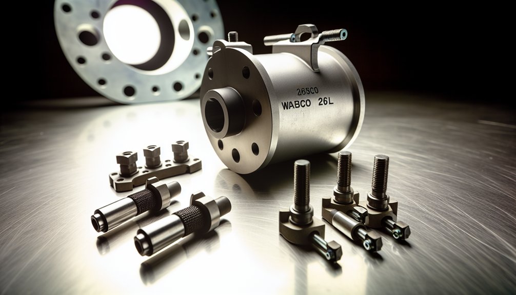
Quick Reference: WABCO Locomotive Valve Clearance Specifications
| Valve Type | Cold Clearance | Hot Clearance | Test Required After Adjustment |
|---|---|---|---|
| Inlet Valve | 0.38 mm | Verify per OEM manual | Compression Test |
| Exhaust Valve | 0.81 mm | Verify per OEM manual | Leak-Down Test |
| Both Valves | Per cylinder sequence | Re-check after torque | Timing Confirmation |
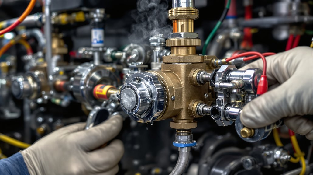
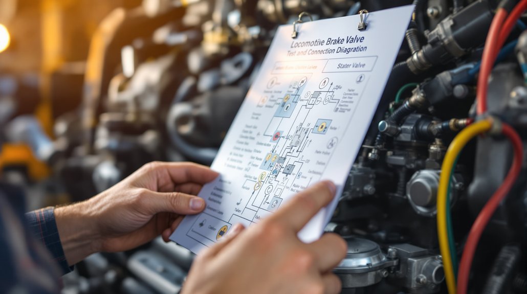
How to Calibrate WABCO Locomotive Valves Correctly
Calibrating WABCO locomotive valves demands strict procedural discipline. Mikura International supplies genuine WABCO locomotive engine parts globally.
Each step below follows OEM-approved standards precisely.
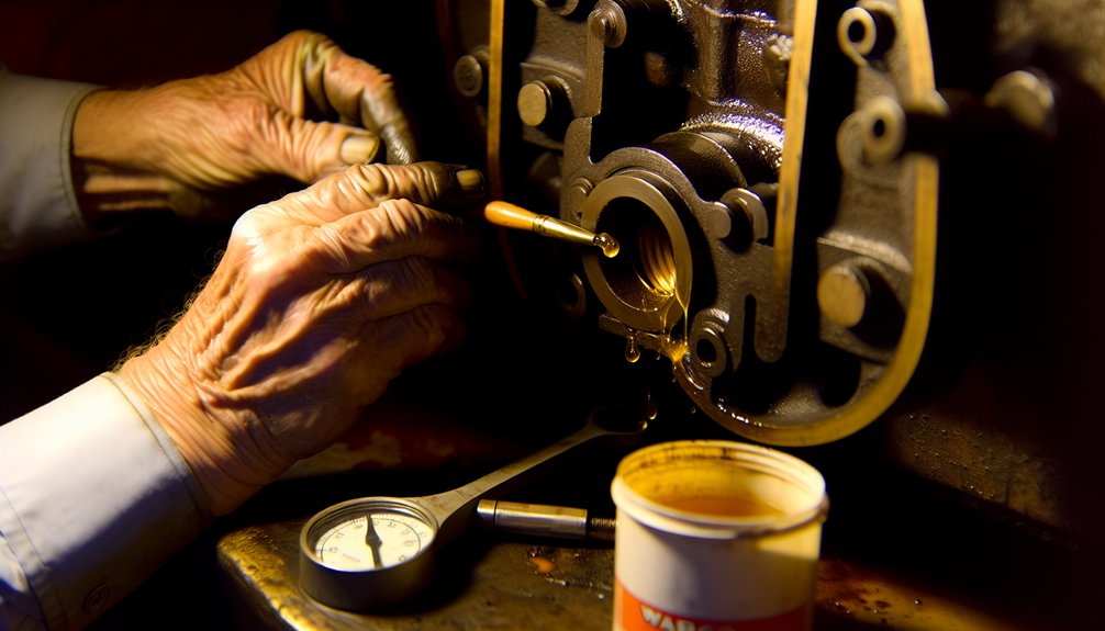
Tip 1 — Complete PPE Checks First
Never begin without proper personal protective equipment. Use gloves, eye protection, and flame-resistant clothing.
This is non-negotiable before touching any locomotive engine component.
Tip 2 — Execute Lockout/Tagout Procedures
Lock out all energy sources completely. Tag every isolation point clearly.
Verify zero electrical and mechanical energy before proceeding.
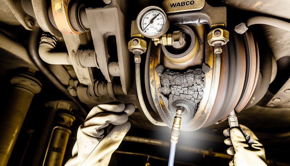
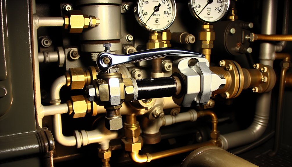
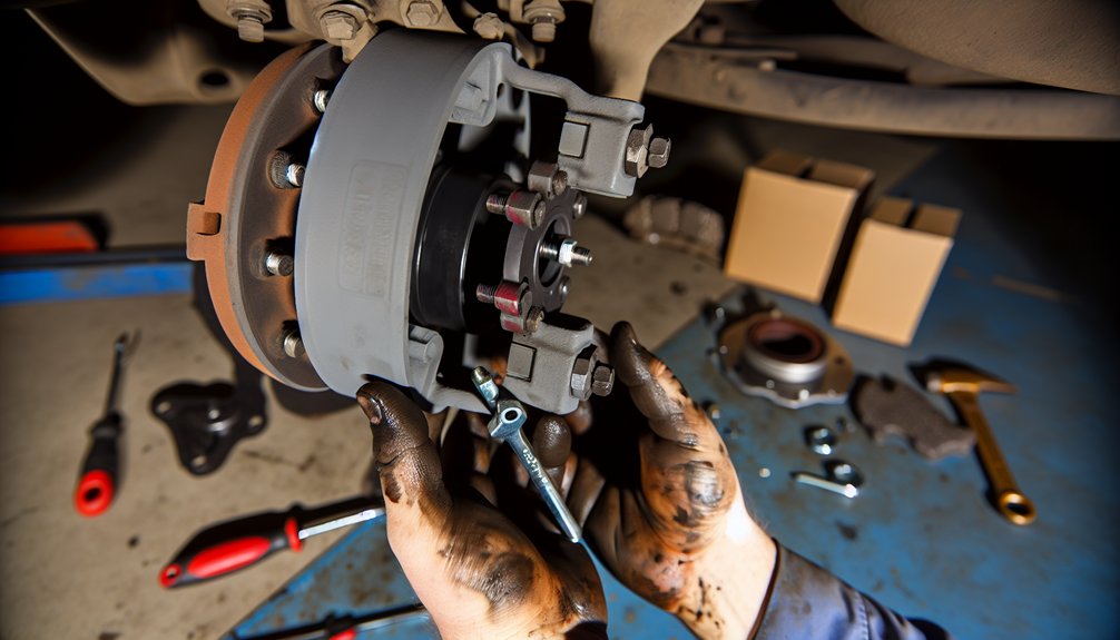
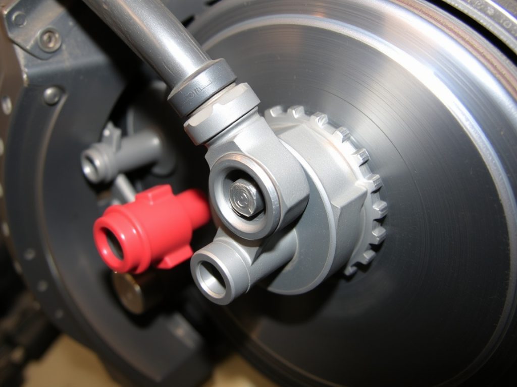
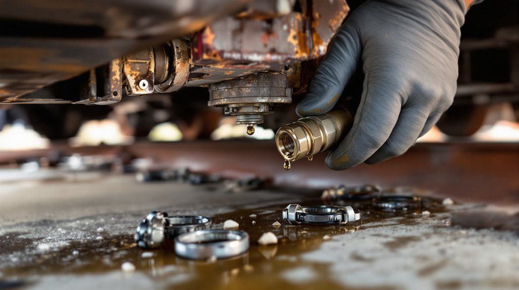
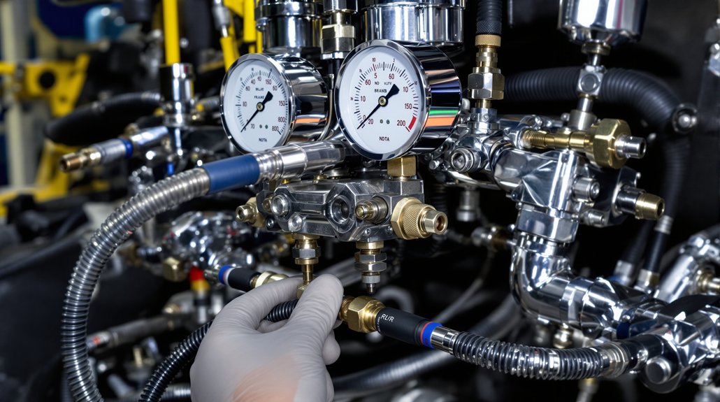
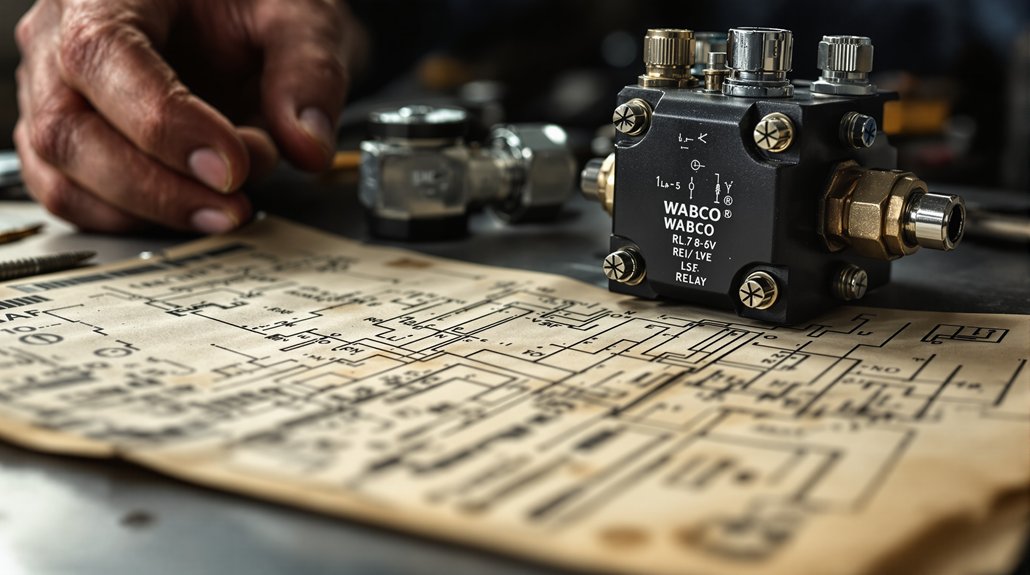
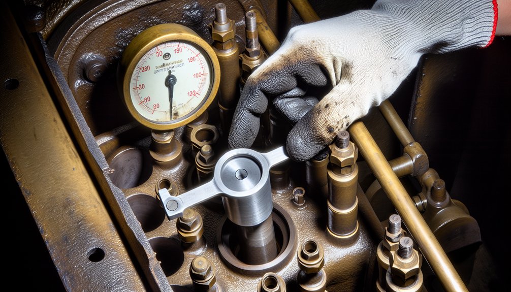
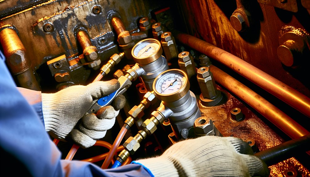
Tip 3 — Verify Zero Brake System Pressure
Confirm zero pressure exists across all brake components. Use a calibrated pressure gauge.
Never touch brake components until pressure reads zero.
Tip 4 — Allow Engine to Reach Cold State
Cold clearance specs apply only to a cold engine. Measurements taken hot will be inaccurate.
Allow sufficient cooling time before measuring.
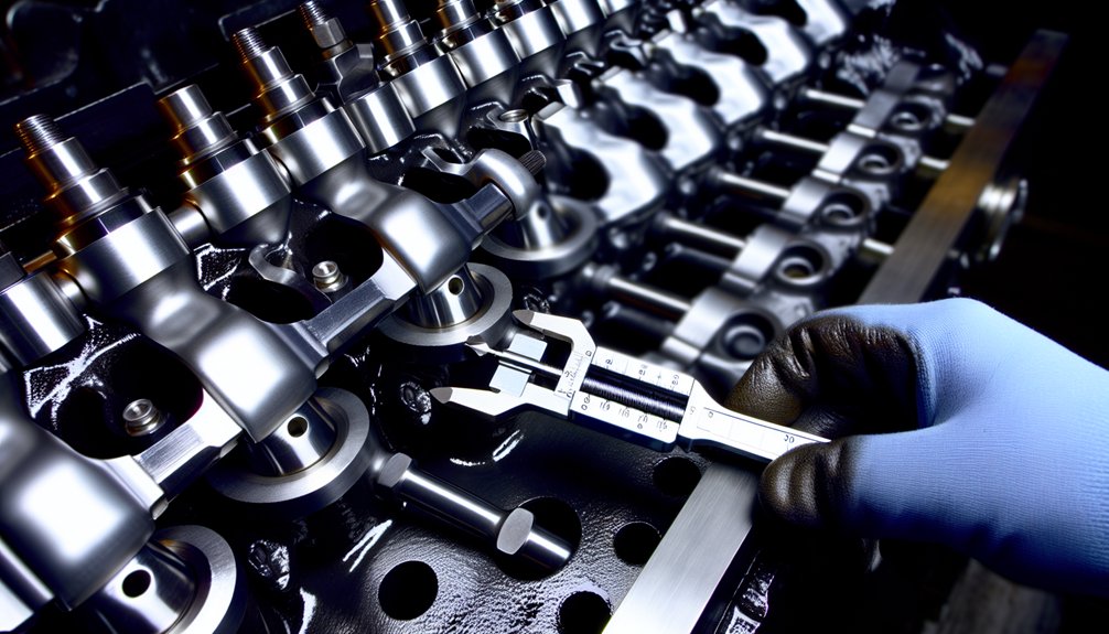
Tip 5 — Set Inlet Valve Clearance to 0.38 mm
Use a calibrated feeler gauge only. Set each inlet valve to exactly 0.38 mm.
Recheck after every adjustment before moving forward.
Tip 6 — Set Exhaust Valve Clearance to 0.81 mm
Exhaust valves require a wider clearance than inlet valves. Set each exhaust valve to exactly 0.81 mm.
Verify with a second feeler gauge pass.
Tip 7 — Follow the Correct Cylinder Sequence
Never adjust valves in random order. Follow the OEM-specified firing sequence strictly.
Out-of-sequence adjustments compromise timing and engine balance.
Tip 8 — Confirm Valve Timing After Adjustment
Timing confirmation is mandatory after every adjustment session. Use a timing indicator tool.
Incorrect timing causes misfires and power loss.
Tip 9 — Run Compression Tests After Every Adjustment
Compression tests reveal sealing issues immediately. Run tests on every cylinder after adjustments.
Record readings and compare against OEM specifications.
Tip 10 — Run Leak-Down Tests After Compression Tests
Leak-down tests identify valve seat and ring issues. Perform them after every compression test.
Address any reading outside acceptable thresholds immediately.
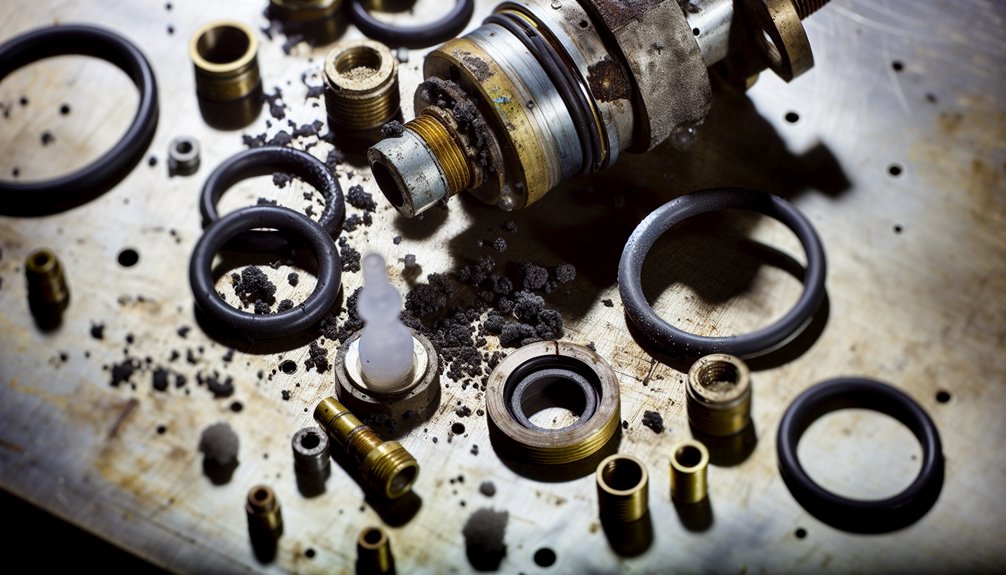
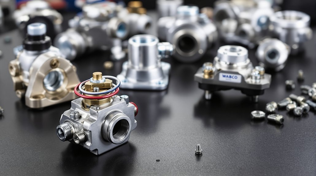
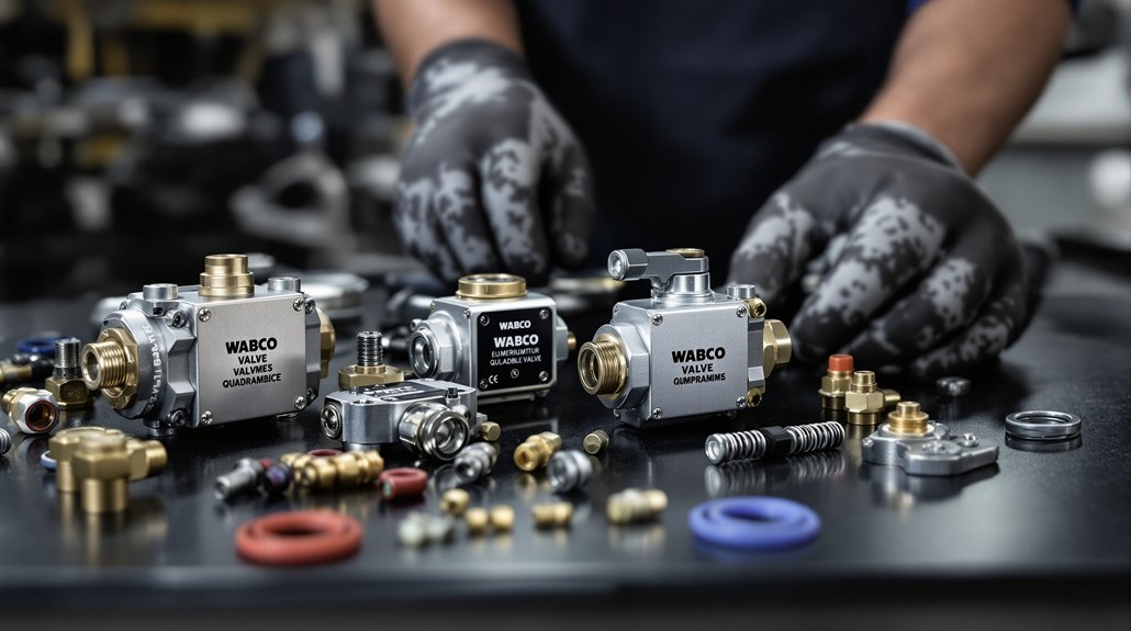
Where to Source Genuine WABCO Locomotive Valve Components
Accurate calibration requires genuine parts. Worn valves and seats cannot hold correct clearances.
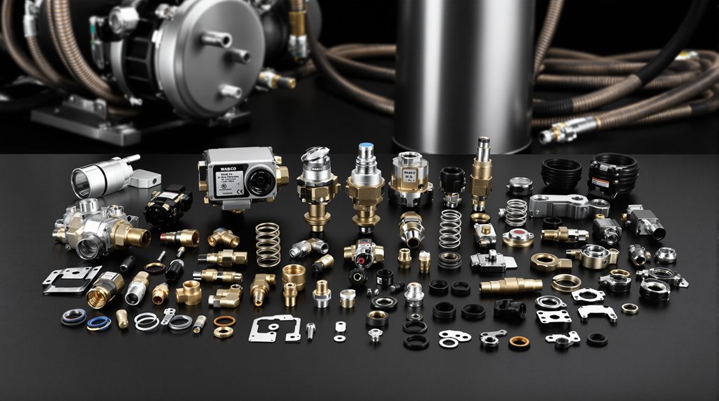
Mikura International supplies genuine locomotive engine parts from WABCO, ALCO, EMD, and GE.
We serve operators and maintenance teams worldwide as trusted importers and exporters of genuine locomotive engine components.
Key Takeaways
- Verify BP pressure reads 5 kg/cm² and complete all hazard assessment and work authorization paperwork before beginning any valve calibration work.
- Inspect PPE including safety glasses, gloves, steel-toed boots, and hearing protection for damage or defects prior to entering the work area.
- Perform full engine shutdown, engage battery disconnect switches, and exhaust brake pipe pressure to zero before touching valve components.
- Distinguish mechanical from hydraulic lifters before calibrating; WABCO systems use mechanical lifters requiring periodic manual lash adjustments with specific clearance ranges.
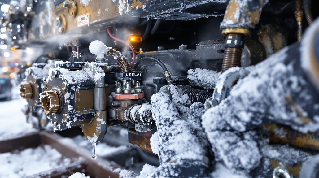
- Rhythmic ticking or clacking from the engine top signals excessive valve lash, most noticeable during idle or cold starts.
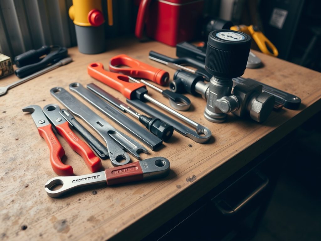
Gather PPE and Tools for Wabco Valve Work Before You Start
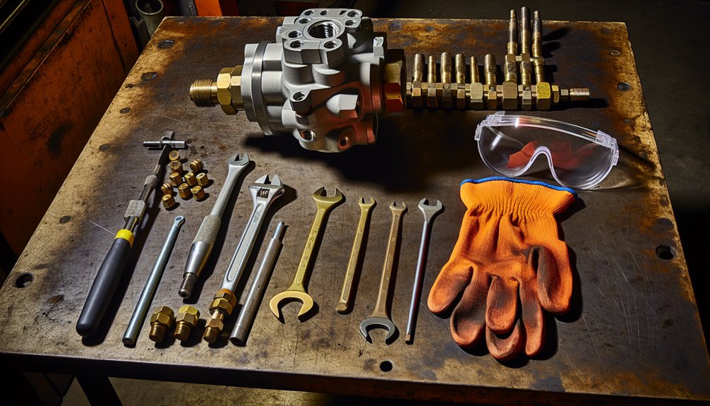
Before beginning WABCO valve calibration work on your locomotive, gather your PPE and tools. You’ll need safety glasses, work gloves, steel-toed boots, hearing protection, and high-visibility clothing. Check each item before use—inspect your safety glasses for lens care issues like cracks or compromised integrity, verify gloves for tears or punctures, and examine boot soles for structural soundness. Test electronic hearing protection for battery function and proper seal.
Before starting WABCO valve calibration, inspect all PPE thoroughly—check glasses, gloves, boots, and hearing protection for damage or defects.
Confirm personal fit on all PPE items to make certain protection performs as intended during locomotive brake valve maintenance.
For tools, collect pressure testing equipment, appropriate cleaning solvents, specified lubrication products, a degree wheel, measurement tools, and documentation materials. Position everything within reach but clear of your immediate work zone.
Complete all hazard assessment forms and work authorization paperwork before proceeding. Verify your workspace has adequate lighting, ventilation, and anti-static measures in place for handling locomotive electronic brake valve components. Log all PPE inspection findings in your maintenance records. During preparation, confirm that BP pressure reads 5 kg/cm² before advancing into any brake system calibration work.
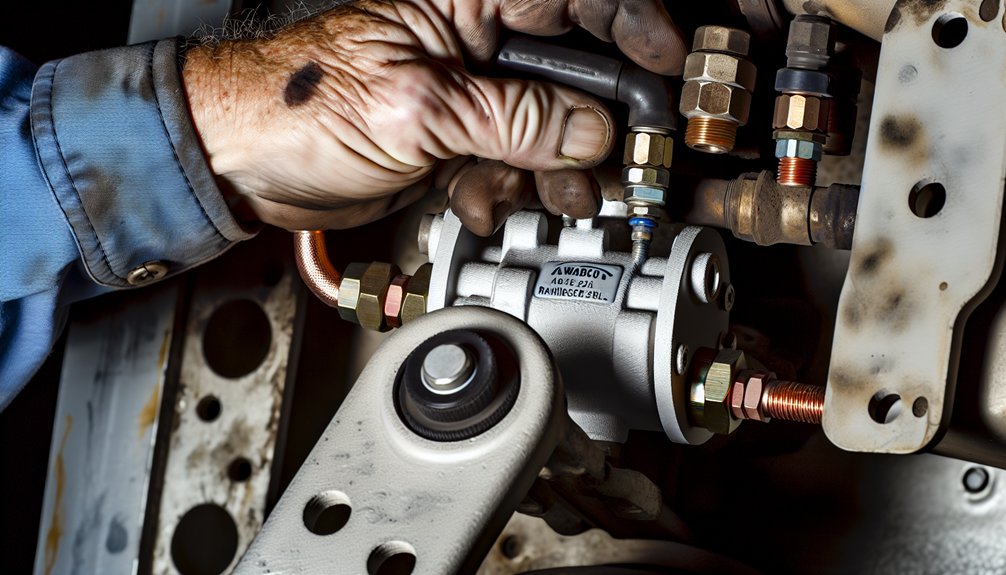
Lock Out and Secure the WABCO Locomotive Before Starting
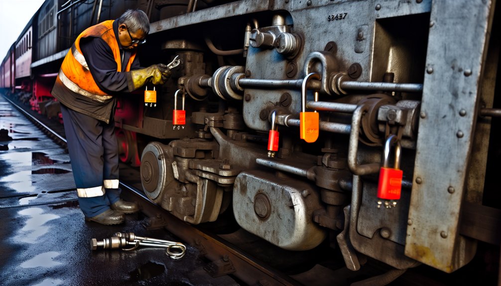
With your PPE on and tools staged, you’ll need to lock out and secure the locomotive before touching any WABCO valve components. Begin by reducing engine speed to idle, then initiate the full shutdown sequence, engaging battery disconnect switches for complete electrical isolation of the ignition system.
Close and lock the main reservoir isolation valve, then manually exhaust air brake pipe pressure to zero psi. Bleed brake chamber air from all connected rail cars through designated ports, then independently verify pressure release on secondary and auxiliary reservoirs. Confirm every gauge reads zero before proceeding.
Block all moving brake linkages with mechanical stops and secure brake cylinders against unintended extension. Apply your personal lock to each energy-isolating device and affix your tag for the duration of work. Employee verification is mandatory — authorized personnel must physically confirm every lockout device is properly secured before valve calibration begins. Document all procedures for regulatory compliance.
Recognize the Signs of Valve Lash Problems on a WABCO Locomotive
When inspecting your WABCO locomotive for valve lash problems, you’ll want to listen for rhythmic ticking or clacking from the top of the engine, as excessive valve clearance causes rocker arms to strike valve stems with greater force, producing noise that’s most pronounced at idle or during cold starts. You should also watch for performance degradation, including power loss, rough idle, and misfires, which signal that insufficient valve lash is preventing valves from fully seating and allowing combustion gases to escape past the valve face.
If you’ve neglected these early warning signs, you’ll likely find permanent heat damage to the valve faces and seats, particularly on exhaust valves that overheat and burn when reduced seating contact time cuts off their primary cooling pathway. Too-tight lash, while less audible than excessive clearance, presents its own danger by causing poor engine performance and loss of compression when the engine reaches operating temperature.
Audible Ticking Clues
One of the earliest signs of valve lash problems you’ll encounter on a Wabco locomotive is a distinct rhythmic ticking or clacking noise coming from the top of the engine. This sound indicates the rocker arm is striking the valve stem with excessive force due to oversized clearance. Audible diagnostics become critical here—the noise is most prominent at idle and low speeds during locomotive operation.
Operator awareness is essential because ticking increases gradually, making it easy to overlook:
- Noise intensifies incrementally, often going unnoticed until significant wear occurs within the locomotive’s valve train assembly
- Properly adjusted valves run quietly and shouldn’t mask other engine sounds critical to locomotive performance monitoring
- A loose rocker arm can mimic valve lash ticking, requiring further inspection to differentiate
Don’t ignore persistent ticking in your locomotive engine—it signals progressive valve train deterioration that can lead to costly operational downtime and compromised traction performance. When ticking is detected, consulting an experienced technician is strongly recommended to accurately diagnose whether the clearance requires adjustment or whether additional valve train components have been compromised.
Performance Loss Signs
Beyond audible clues, valve lash problems reveal themselves through measurable performance degradation that directly impacts your locomotive’s pulling capability and operational efficiency. You’ll notice idle hesitation, torque fluctuation, and uneven power delivery across varying operating conditions and load demands.
| Symptom | Cause | RPM Range |
|---|---|---|
| Low-end tractive effort loss | Tight intake valves reducing cylinder fill | Low RPM |
| Valve float risk | Excessive lash overworking valve springs | High RPM |
| Rough idle instability | Disrupted combustion cycle sequencing | Idle |
| Sluggish throttle response | Multiple cylinders with incorrect clearance | Light load |
| Below-spec compression readings | Valve face or seat degradation | All ranges |
These symptoms become especially critical in heavy-haul locomotive operations, where consistent power output across all cylinders directly determines grade-climbing performance and consist handling reliability. A single maladjusted cylinder can cascade into broader power plant inefficiencies that compromise an entire run.
Run compression and leak-down tests on affected cylinders to properly diagnose the root cause. Strong leak-down results paired with low compression readings confirm clearance problems rather than valve integrity failures, allowing maintenance teams to target adjustments precisely without unnecessary component replacement. Excessively tight exhaust valve clearance is particularly damaging, as burned valves and head damage can develop gradually before any dramatic performance failure becomes apparent.
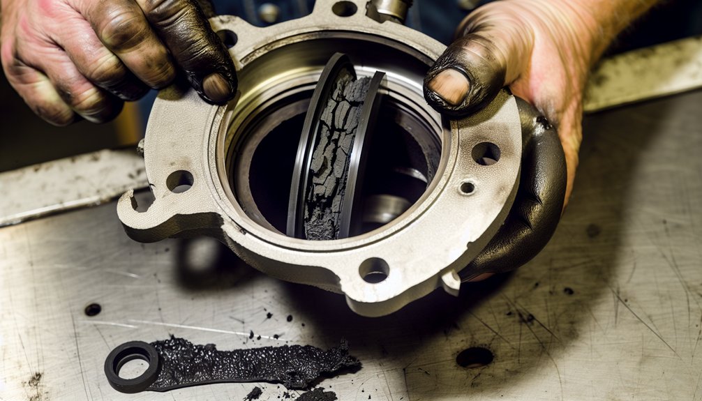
Valve Heat Damage
Watch for these critical indicators in locomotive diesel engines:
- Burned valve faces showing dark discoloration, pitting, and seat recession during cylinder head inspection of locomotive power assemblies
- Metal debris particles in oil samples confirming valve face material degrading into the crankcase of the locomotive engine
- Blue-gray exhaust smoke combined with 15-25% increased fuel consumption signaling compression loss in locomotive cylinder units
Thermal fatigue cracks radiating from valve seat areas and hissing sounds at the locomotive cylinder head confirm advanced damage requiring immediate corrective action before complete valve failure occurs, risking costly traction motor downtime and unscheduled locomotive withdrawals from service. Incorrect clearance between the valve stem and rocker arm disrupts precise valve timing, accelerating heat buildup and valve face deterioration in locomotive power assemblies.
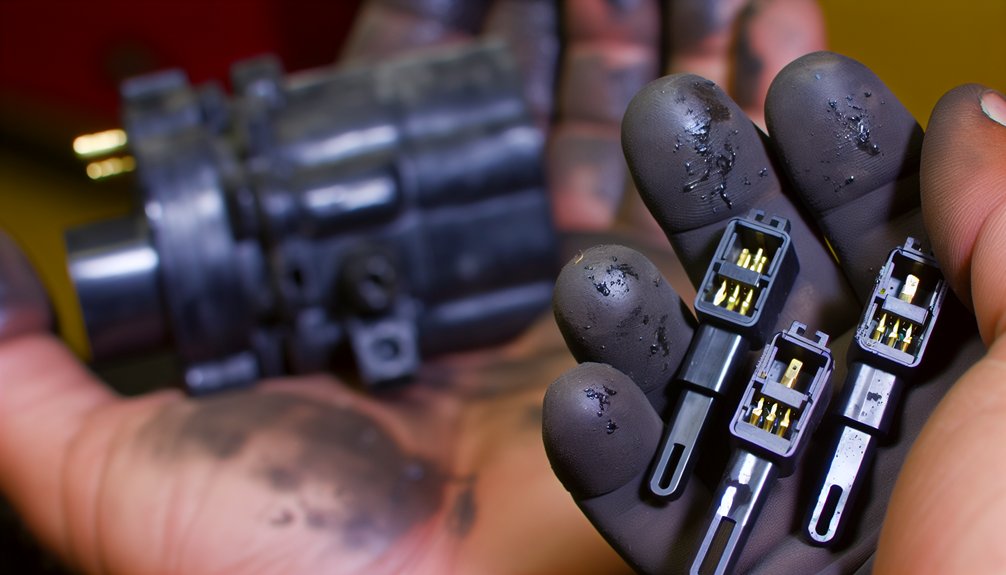
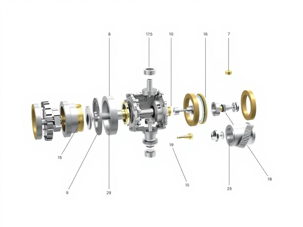
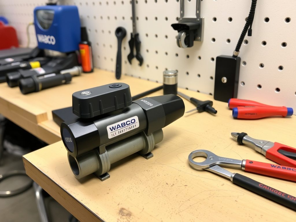
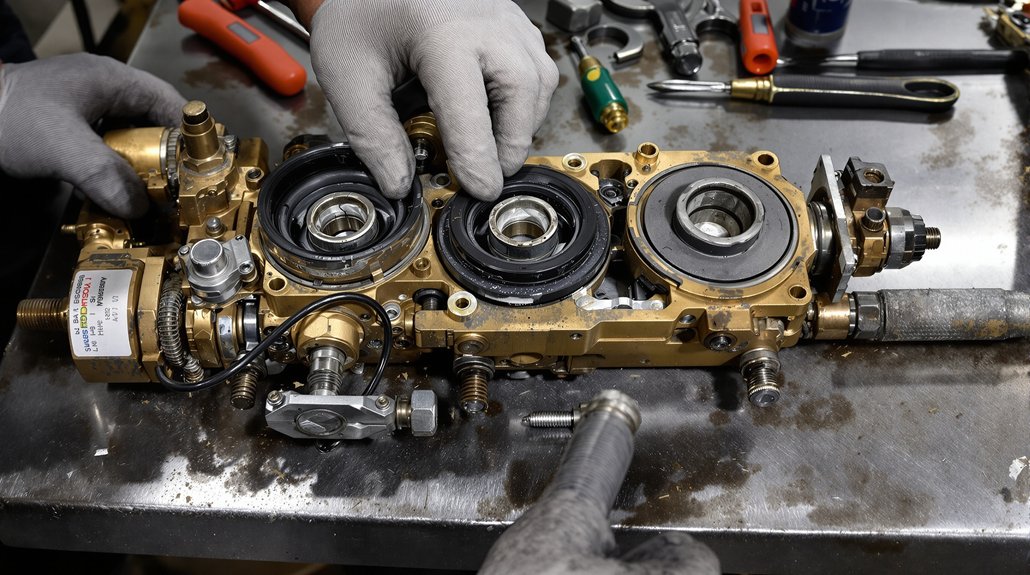
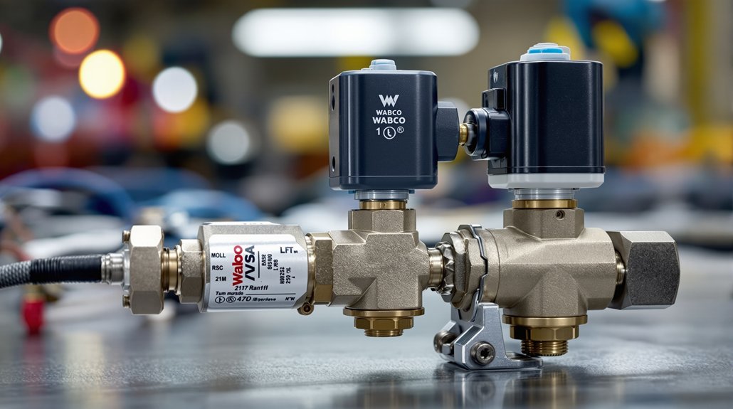
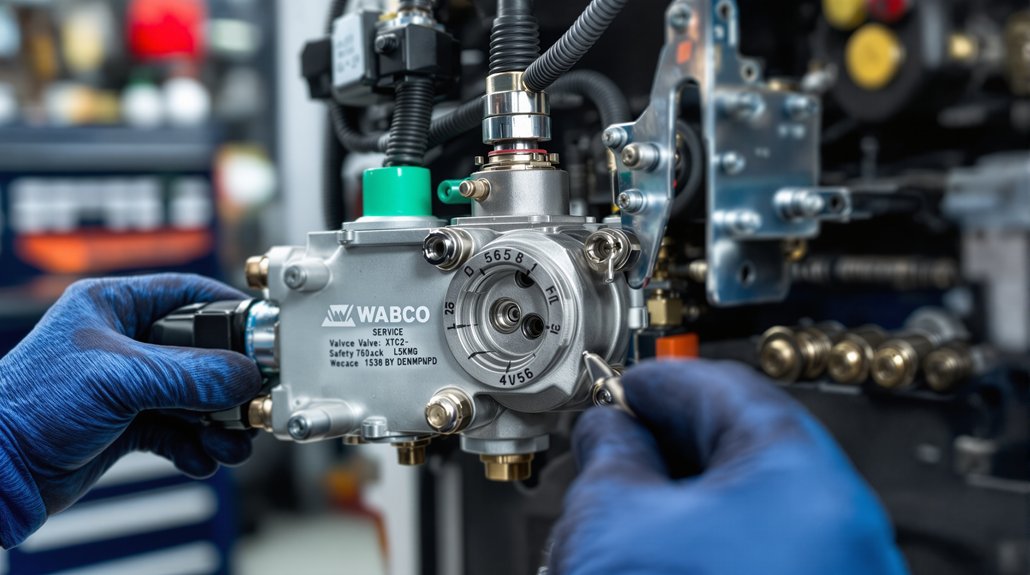
Identify WABCO Diesel Valve Train Components Before You Calibrate
Before you calibrate any Wabco diesel valve train, you’ll need to distinguish between mechanical and hydraulic lifters, since each type requires a different adjustment procedure and tolerates a different range of lash. Inspect key valve train parts—including rocker arms, pushrods, camshaft lobes, and valve stems—for visible wear patterns such as pitting, scoring, or uneven contact surfaces that signal component degradation. Once you’ve identified the lifter type and assessed part condition, you can determine whether wear symptoms require component replacement before calibration proceeds or whether adjustment alone will restore proper valve operation.
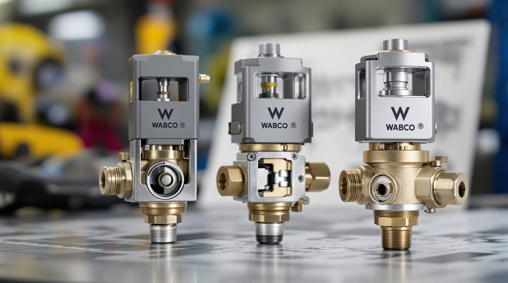
Mechanical Versus Hydraulic Lifters
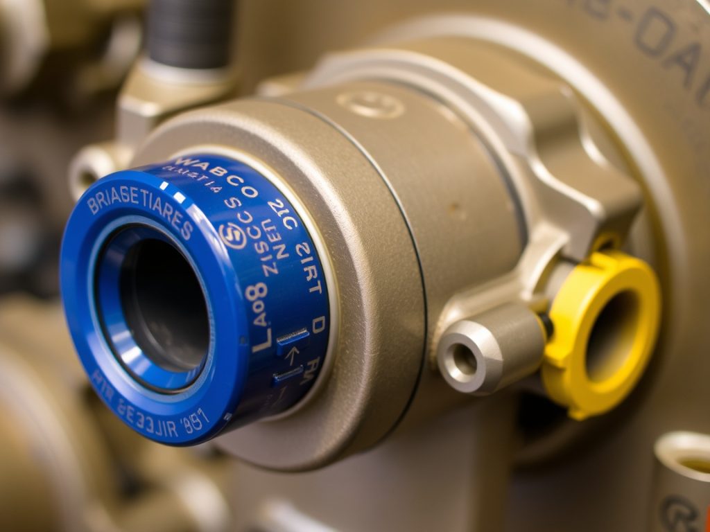
Identifying whether your WABCO diesel valve train uses mechanical or hydraulic lifters determines every calibration step that follows, so you’ll need to confirm the lifter type before touching any adjustment hardware.
WABCO locomotive compressor systems use mechanical valve lifters, meaning you’ll manage thermal expansion manually through periodic lash adjustments rather than relying on automatic self-correction.
Key distinctions shaping your calibration approach:
- Mechanical lifters require measured static clearance to accommodate thermal expansion during locomotive engine heating cycles
- Hydraulic preload settings during installation are critical in hydraulic designs, where oil contamination triggers internal failure rather than simple misadjustment
- Rhythmic ticking confirms excessive mechanical lash, while noisy hydraulic lifters signal pressure or contamination problems specific to locomotive operating conditions
Knowing which system you’re servicing on your locomotive engine prevents misdiagnosis and incorrect corrective action.
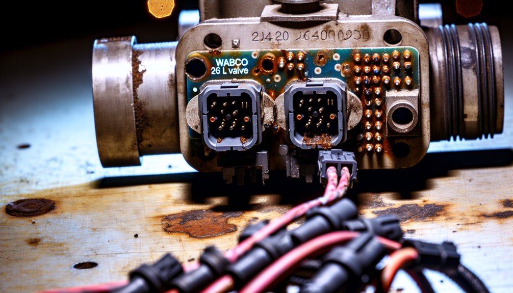
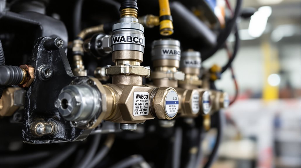
Key Valve Train Parts
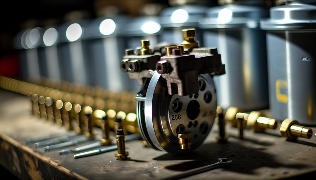
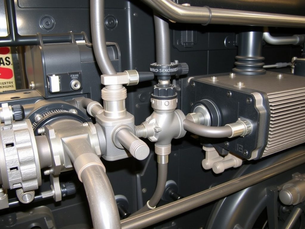
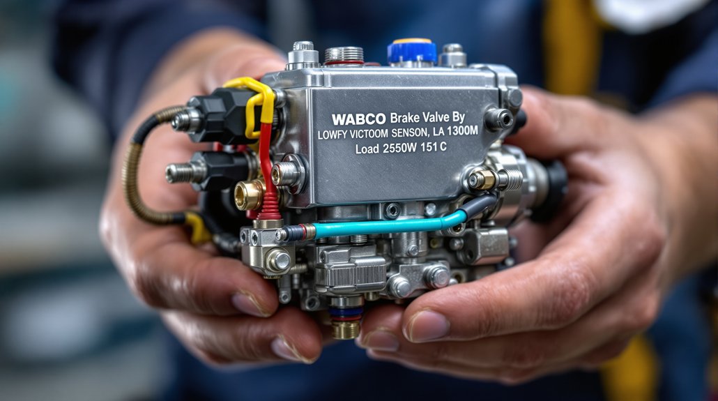
Mapping the diesel valve train before calibration prevents misidentification errors that cascade into incorrect adjustments across the entire braking and pressure control system of a locomotive. You’ll encounter service valves, emergency valves, and control chambers working as an integrated unit—each requiring individual identification before you touch an adjustment point.
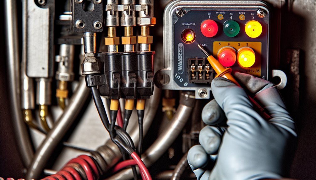
Confirm port designations first. Supply ports (11/12), delivery ports (21–24), and control ports (41/42) each carry distinct functional roles within relay circuits connecting ECU outputs to axle-specific brake cylinders in locomotive braking assemblies. Misreading one port misaligns your entire calibration sequence.
Next, locate diaphragm assemblies governing load-sensing functions across pressure differential chambers within the locomotive valve train. These respond to pressure changes, so positional errors during calibration produce compounding inaccuracies. Cross-reference component part numbers against physical air-hose layouts and OEM connector coding before proceeding to any measurement or adjustment step.
Recognizing Wear Symptoms
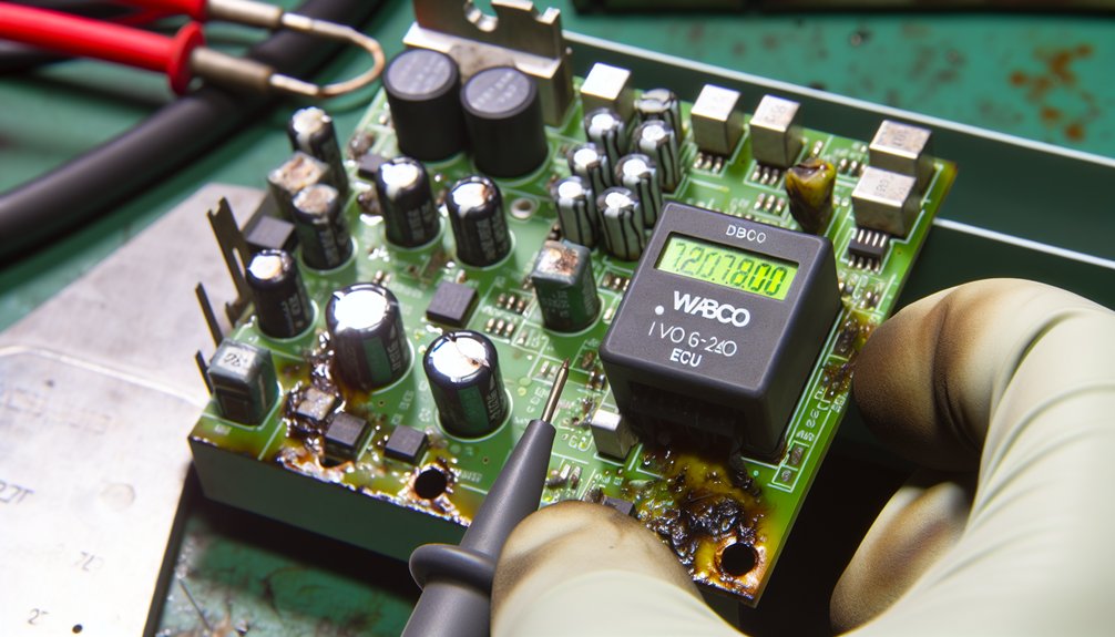
Worn valve train components in locomotive engines routinely announce their degradation before they fail completely, and you’ll catch these signals faster when you know what to listen and look for. Acoustic diagnostics reveal diaphragm degradation through distinct pressure pops, hissing during brake activation, and grinding from chamber assemblies. Dashboard warning indicators confirm what your ears detect—pressure imbalances signal compromised seals before catastrophic rupture occurs.
Watch for these critical indicators:
- Pressure loss: 60–70 PSI drops within minutes of locomotive engine shutdown signal failing diaphragms
- Delayed brake response: Sluggish pedal engagement means worn diaphragms can’t generate sufficient pressure quickly enough to meet the demands of locomotive braking systems
- Compressor strain: Excessive heat and vibration indicate air escaping through deteriorated seals within the locomotive’s braking assembly
Address these symptoms immediately—continued operation of a locomotive with these warning signs risks complete braking system failure, posing serious safety hazards across the rail network.
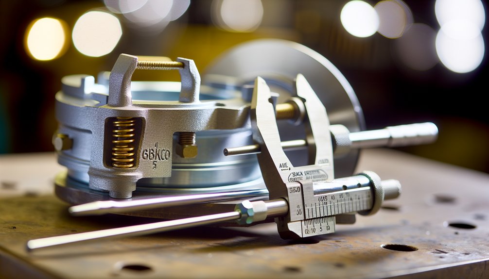
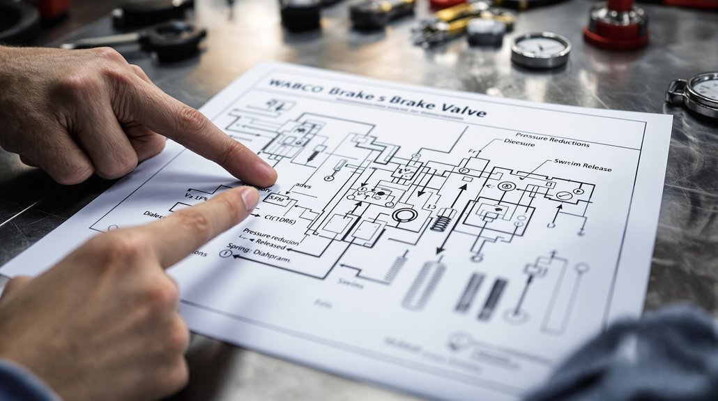
Pull the Correct WABCO Cold and Hot Clearance Specs
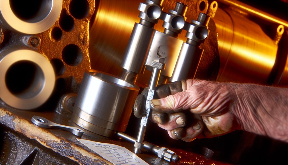
Before you begin any valve adjustment on a WABCO system, you’ll need to pull the correct cold and hot clearance specs for your specific locomotive engine. These spec tolerances aren’t interchangeable, so precision matters from the start.
For cold clearance, set your inlet valve to 0.38 ± 0.08 mm (0.015 ± 0.003 inch) and your exhaust valve to 0.81 ± 0.08 mm (0.032 ± 0.003 inch). Take these measurements only when the locomotive engine is fully stopped, placing your feeler gauge between the rocker arm and valve bridge with valves completely closed.
Hot clearance specs account for thermal expansion across the locomotive engine’s operational temperature range. As the engine heats up, metal components expand, shifting your clearance values. You’ll need to document both cold and hot specs before proceeding, since extended operation cycles establish stable hot clearance equilibrium and directly impact your final adjustment accuracy. After completing all valve adjustments, always remove the timing bolt from the flywheel and reinstall the timing cover before returning the locomotive to service.
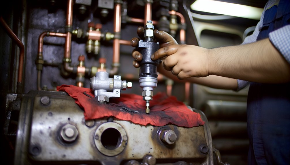
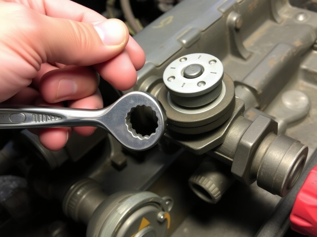
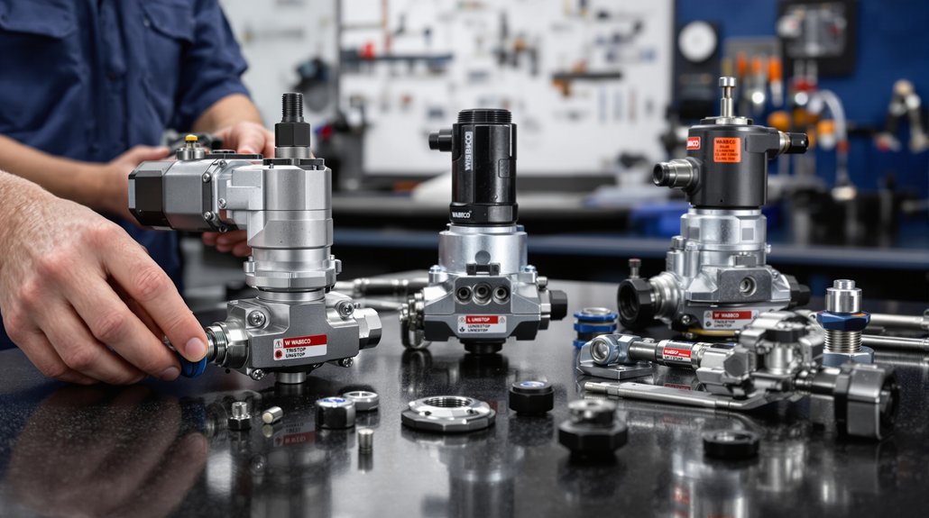
Set Valve Lash Accurately on Wabco Mechanical Lifters
Setting valve lash accurately on WABCO mechanical lifters starts with positioning each lifter on the cam base circle—the heel of the camshaft—before you take any clearance measurement. Rotate the engine by hand until the lifter rests fully on the cam base circle, confirming it’s off the opening and closing ramps. Misplacement here produces incorrect lash that’ll fail under hot locomotive operating conditions.
Apply your feeler technique by sliding the correct gauge thickness between the rocker arm tip and valve stem tip:
- Heavy drag confirms proper clearance achievement
- Free sliding without binding verifies the lash stays within specification
- Recheck after lock-down to detect any thousandths-of-an-inch variation introduced by the locking mechanism
If post-lock verification shows clearance degradation, release and readjust immediately. This systematic approach prevents valve train noise and premature component wear throughout the locomotive engine’s service life. Flat tappet valvetrains require engine oil containing Zinc and Phosphate to prevent rapid cam lobe and lifter wear that can occur within minutes of initial operation.
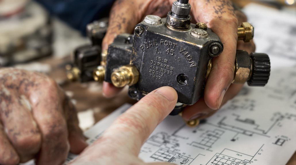
Use a Degree Wheel to Confirm WABCO Valve Timing Is Exact
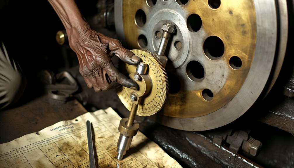
Confirming Wabco valve timing with a degree wheel in a locomotive engine begins at the crankshaft nose, where the wheel must be mounted securely and the pointer positioned directly above its surface without contact. Ensure wheel markings remain fully legible throughout the entire timing check procedure under locomotive operating conditions.
Secure the degree wheel firmly at the crankshaft nose, keeping the pointer clear and all markings legible throughout.
Next, align the degree wheel to TDC using manufacturer reference marks, then verify BDC positioning. Lead values must remain consistent at both dead center positions regardless of cutoff adjustments specific to locomotive steam distribution requirements.
Using degree wheel measurements, identify lobe centerline positions where maximum valve lift occurs within the locomotive engine assembly. Record duration measurements capturing total crankshaft degrees from valve opening through closing at specified lift thresholds. Calculate valve overlap by determining where intake and exhaust valves maintain simultaneous opening across the locomotive’s operating range.
Compare all recorded readings against WABCO camshaft specifications applicable to the locomotive engine configuration. Any deviations require eccentric crank repositioning to restore correct timing within the locomotive drivetrain. Document baseline measurements before adjustments and post-adjustment readings to confirm WABCO valve timing accuracy meets exact specifications, ensuring reliable locomotive engine performance and operational efficiency. When one piston reaches TDC, the opposite piston position on a two-cylinder locomotive will fall slightly to the BDC side of the halfway point due to connecting rod angularity.
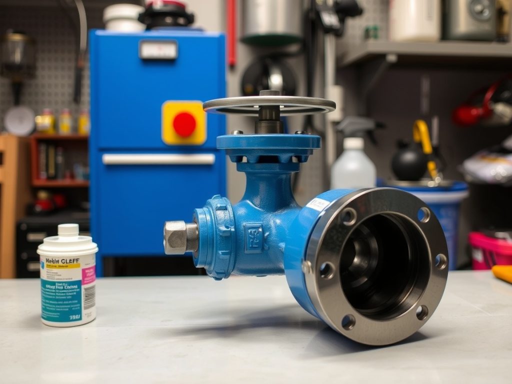
Lubricate WABCO Valve Gear Correctly After Every Adjustment
After every valve timing adjustment, you’ll need to select Rocol 1000 or a compatible NLGI 1-2 grade grease specifically rated for WABCO locomotive systems before applying anything to exposed components. Before you apply fresh lubricant, clean each joint surface, bushing seat, and bearing face thoroughly to remove metal particles, carbon deposits, and degraded grease that would otherwise accelerate abrasive wear. Contaminated surfaces compromise the integrity of any new lubricant film, so don’t skip the cleaning step regardless of how minor the adjustment was. After lubrication, confirm that adjustment nuts remain tight so that valve centering does not require repetition.
Selecting Proper Lubricant Grade
Selecting the right lubricant grade for WABCO valve gear in locomotive applications starts with understanding NLGI classification standards, where grades 1–2 represent the medium viscosity specifications best suited for valve mechanism applications. These grades balance flow characteristics with staying power across expansion links, radius rods, and combination lever joints. You’ll also need to verify package compatibility with your specific valve model and sealing system design.
Consider these critical selection factors:
- Cold flowability performance below 6°C guarantees consistent lubrication during cold weather locomotive operations and heat activation requirements
- Sealing capacity calculations based on bearing seat dimensions prevent injection port blockages from excessive grease application
- Material composition of valve components must align with your chosen grease formulation’s additive package
Improper grade selection accelerates seal deterioration and compromises valve operability testing outcomes in locomotive service conditions.
Cleaning Before Applying Grease
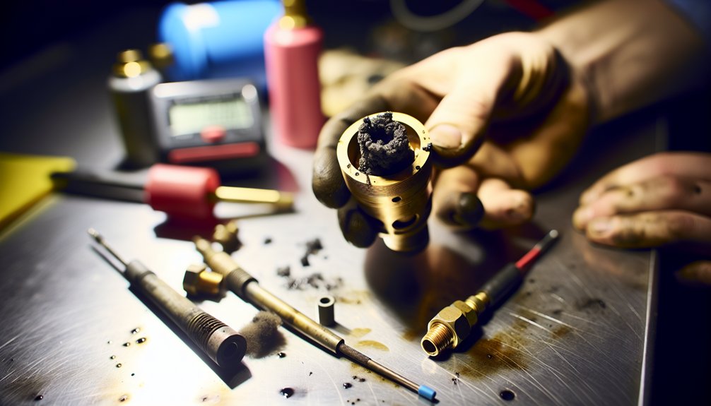
Once you’ve matched your lubricant grade to your locomotive valve gear specifications, the condition of the surfaces receiving that grease determines whether your selection pays off. Use compressed air to dislodge accumulated debris from expansion links and radius rod connections. Avoid wire brushes near critical valve surfaces and bearing areas since they’ll scratch precision components.
For steam-sensitive components on locomotive valve assemblies, control your cleaning temperatures carefully to prevent thermal shock to cast iron parts. After cleaning, use lint-free cloths to eliminate fiber contamination that causes valve sticking and adjustment drift in slide valve and piston valve configurations. Set heat guns to low temperatures to evaporate remaining moisture without warping valve gear linkages.
Document pre-cleaning wear patterns and corrosion spots before applying fresh lubricant, establishing baseline conditions for future locomotive maintenance comparisons. Increased wear in valve gear linkages produces later valve opening, so noting and recording these wear spots before lubrication helps identify components approaching the threshold where balanced port opening across forward and reverse running becomes compromised.
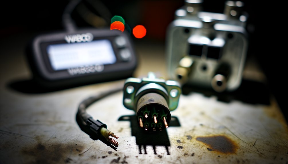
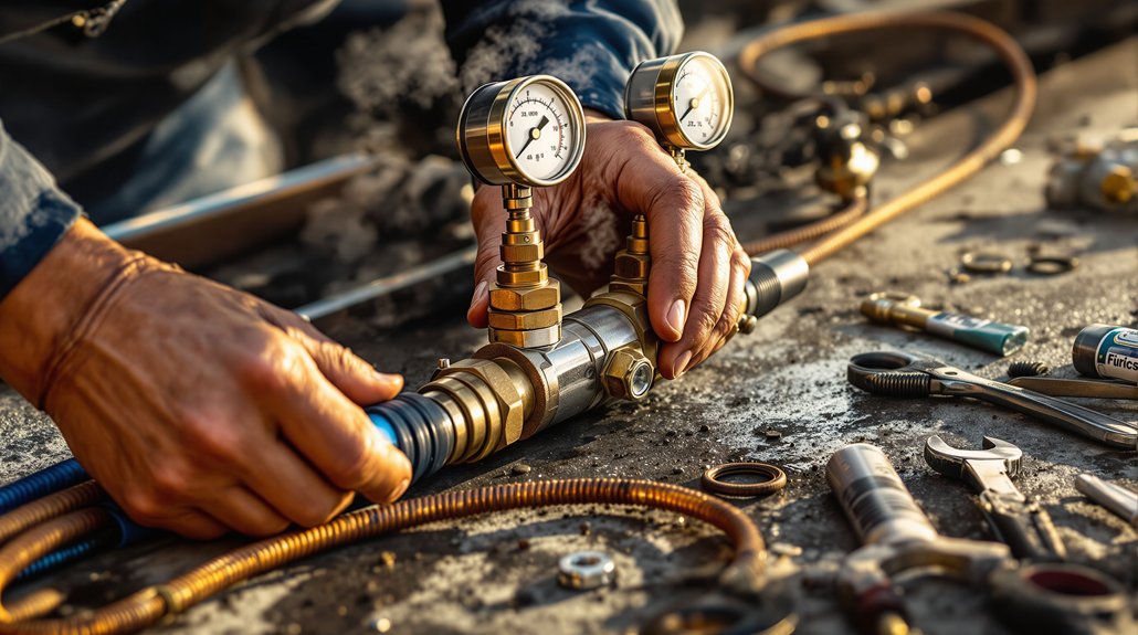
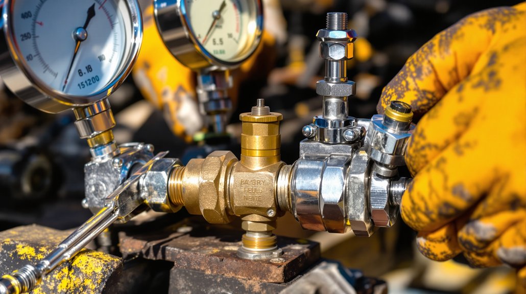
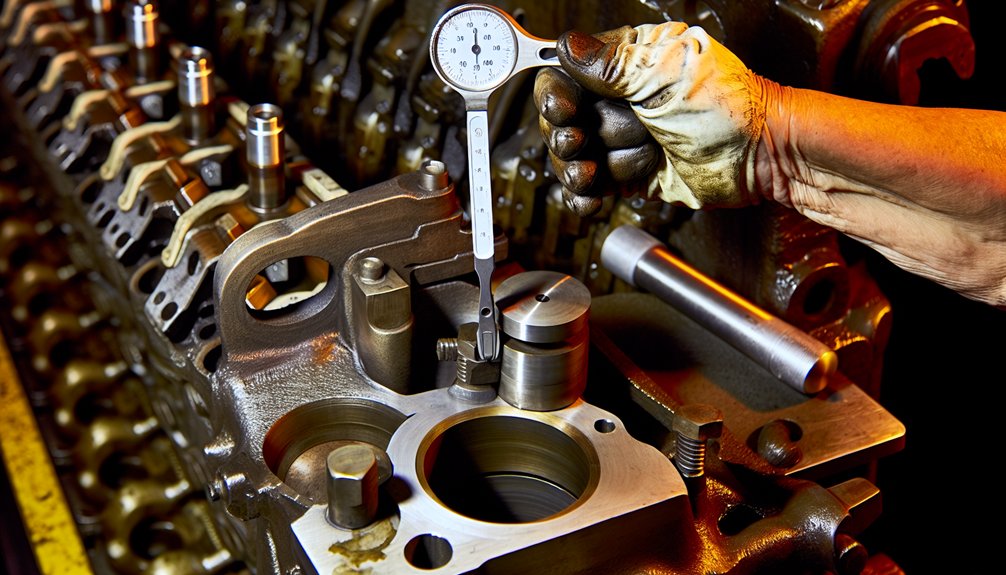
Run Compression and Leak-Down Tests to Confirm WABCO Valve Performance
Running compression and leak-down tests on your WABCO valve system requires methodical preparation before any disassembly begins. Shut down the locomotive engine, remove all necessary access covers, and rotate the crankshaft to top dead center. This position locks both intake and exhaust valves closed, establishing proper cylinder sealing for accurate pressure diagnostics across the locomotive’s braking and air systems.
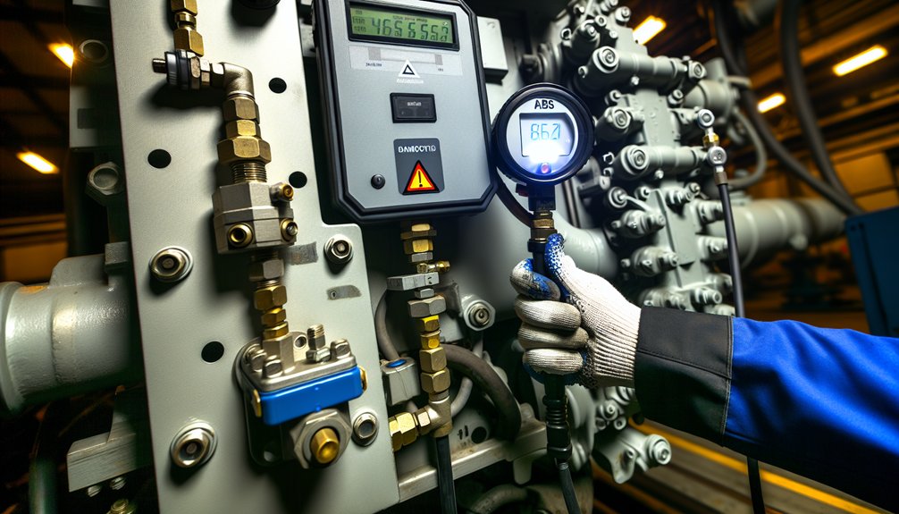
Connect your leak-down tester adapter, matching thread specifications to the designated test port precisely. Your industrial air compressor supplies consistent input pressure through the hose assembly during the diagnostic procedure. A leak percentage reading of 20% or more generally signals inadequate cylinder sealing and warrants further mechanical investigation.
Monitor these critical benchmarks during testing:
- Control pressure must reach 7 bar at cut-off for valid WABCO performance verification
- Brake pipe leakage must stay under 5 pounds per minute
- Main reservoir leaks cannot exceed 3 pounds per minute
Document every pressure reading and leak percentage throughout the locomotive air brake circuit. Pressure loss in a locomotive application indicates piston ring deterioration, compromised valve seats, or cylinder wall damage requiring immediate component inspection and service. Given the safety-critical nature of locomotive braking systems, any readings outside acceptable thresholds demand prompt corrective action before the unit returns to active rail service.
Keep a WABCO Valve Calibration Log That Actually Gets Used
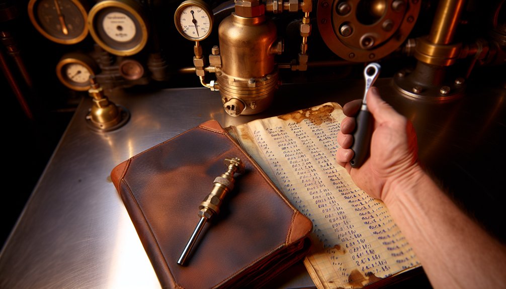
Pressure readings and leak percentages documented during WABCO valve testing serve their full diagnostic value only when systematically recorded and consistently referenced across locomotive service intervals. Standardize your forms to capture compressor model, serial number, and component identification for digital traceability throughout maintenance cycles specific to locomotive applications.
Pressure readings only deliver diagnostic value when systematically recorded and consistently referenced across locomotive service intervals.
Log pressure readings at specific engine speeds, documenting control pressure at 7 bar cut-off specifications relevant to locomotive braking and air supply systems. Record ambient temperatures, particularly during operations below 6°C where heat activation protocols become critical to safe locomotive function. Include technician certification levels to maintain qualified personnel accountability across depot maintenance teams.
For maintenance integration, timestamp coupling wear measurements exceeding 7mm and document genuine WABCO part numbers for warranty tracking within locomotive overhaul schedules. Establish oil consumption baselines against 12 bar pressure line test results to detect deterioration trends before they compromise locomotive air system reliability.
User adoption depends on accessibility. Store records in a digital database enabling rapid retrieval of historical data for trend analysis across locomotive fleets. When technicians can quickly reference previous tightness tests, cut-off pressure benchmarks, and bearing clearance measurements from earlier service intervals, the calibration log becomes an active diagnostic instrument embedded in the locomotive maintenance workflow rather than archived paperwork gathering dust between scheduled inspections. Using WABCO TOOLBOX PLUS software, technicians can cycle individual valves or all valves in sequence to verify correct installation and wiring during scheduled locomotive valve assessments.
Frequently Asked Questions
How Often Should WABCO Valve Calibration Be Performed Between Major Overhauls?
Like clockwork ticking in a complex locomotive system, you’ll need to perform WABCO valve calibration at every 368-day interval between major overhauls. You must conduct scheduled inspections within these cycles, documenting all pressure tests and component verifications specific to locomotive braking systems. Don’t overlook seasonal adjustments, as locomotive operating conditions and environmental factors change throughout the year. You’re required to verify proper charging within 15 psi of operating pressure and maintain brake pipe leakage under 5 lbs/min during each cycle to ensure the continued safe and efficient performance of your locomotive’s braking infrastructure.
Can WABCO Valve Calibration Be Performed Safely by a Single Technician Alone?
While solo safety is possible, you shouldn’t attempt WABCO valve calibration entirely alone on locomotive braking systems. You’ll need remote monitoring capabilities or a second technician to observe pressure readings at multiple test points simultaneously. Critical pressure differentials between the brake pipe and reservoir systems in locomotive applications require concurrent observation. If you must work alone, verify that remote monitoring equipment is fully active and that qualified WABCO technical support remains available throughout your calibration procedure.
What Is the Typical Cost of Professional WABCO Valve Calibration Service?
Typical pricing for professional WABCO valve calibration in locomotive applications ranges from $500 to $2,500, depending on service tiers and system complexity. For a regional rail operator facing an emergency recalibration, expedited same-day service can run $1,500–$3,000. Diagnostic fees before work begins typically fall between $150–$400, plus $85–$150 per hour in labor costs. Preventive maintenance contracts for locomotive braking and pneumatic systems can reduce overall costs by 15–30% compared to individual service rates.
Are WABCO Valve Calibration Procedures Different for Older Versus Newer Locomotive Models?
Yes, WABCO valve calibration procedures differ markedly between older locomotive models and newer locomotive models. With older locomotives, technicians rely on mechanical tools such as degree wheels, dead-center indicators, and manual pressure gauges to verify pneumatic timing across braking and control systems. With newer locomotive models, the process shifts toward ECU diagnostic interfaces, multimeters, and manufacturer-specific software to calibrate solenoid controls and sensor feedback loops with greater precision. It is critical to match your procedures and equipment precisely to your locomotive’s generation, as applying the wrong calibration method can compromise braking performance, air distribution accuracy, and overall operational safety on the rail line.
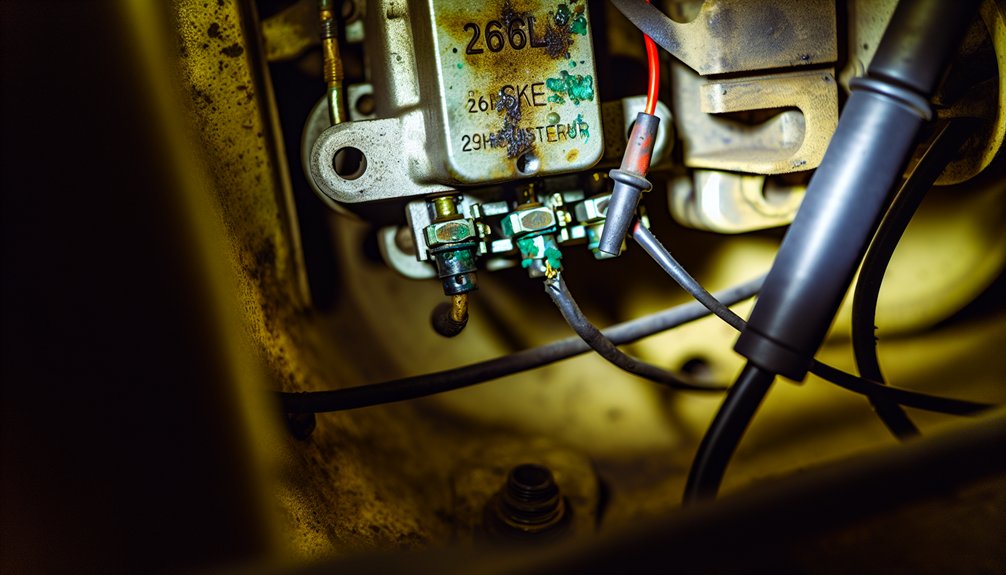
Which WABCO Locomotive Models Require the Most Frequent Valve Calibration Intervals?
Frequent maintenance models requiring your closest attention include pre-2000 WABCO locomotive assemblies (every 120 days), high-frequency duty cycle units in yard switching operations (every 120-150 days), and load-sensing diaphragm systems used in locomotive brake applications (every 180-240 days). If you’re managing high-usage locomotive fleets operating beyond 500,000 hours, monthly calibration checks become essential. Standard 26L locomotive models require calibration every 368 days, making aging locomotive equipment and yard-service units your most demanding calibration priorities.