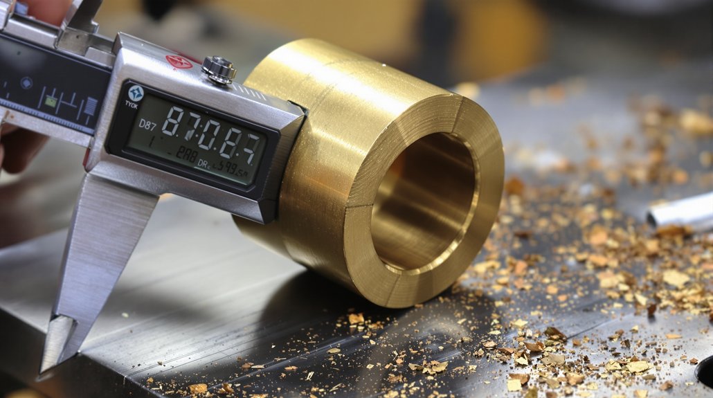
When your EMD generator coupling bushings are failing, you’ll notice rhythmic knocking, elevated drivetrain vibration, and erratic voltage output. Before purchasing a replacement kit, verify the bushing bore diameter, outer diameter, and elastomer durometer rating against your specific locomotive’s OEM specs. During installation, use a soft mandrel to press the bushing evenly and check seating depth with a dial indicator. Keep exploring to sharpen your bushing selection and installation process.
Key Takeaways
Verify bushing bore diameter, outer diameter, and length match OEM specifications for your specific EMD locomotive model before purchasing.
Match the bushing kit’s dynamic load capacity to your generator’s continuous torque output to prevent premature fatigue failure.
Use soft mandrels to evenly distribute pressing force and apply light assembly lubricant to the outer diameter during installation.
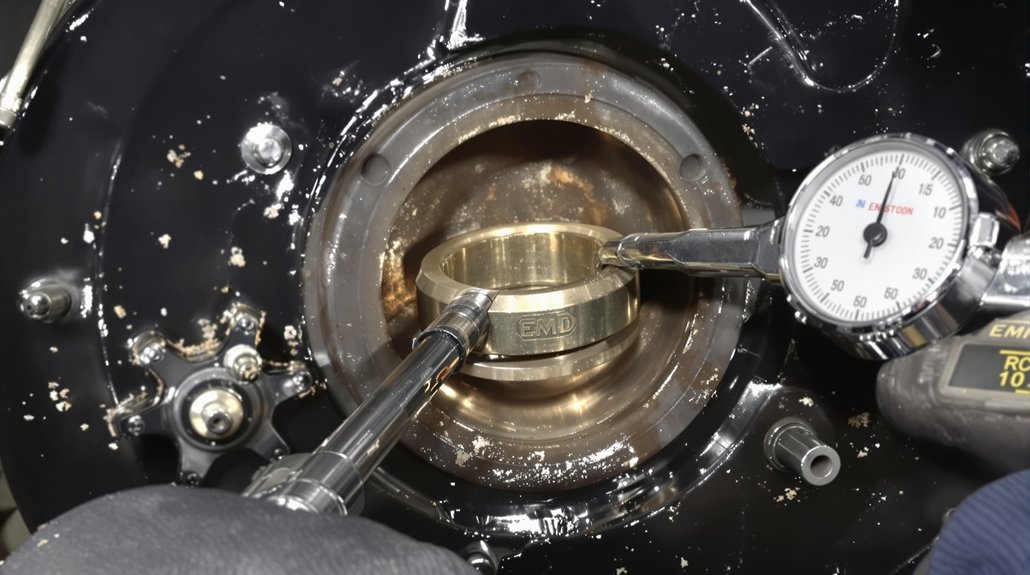
Check seating depth with a dial indicator after installation to confirm proper alignment between the bushing bore and coupling housing.
Select kits rated for your duty cycle, as mismatched load ratings between light switching and heavy mainline service accelerate wear.
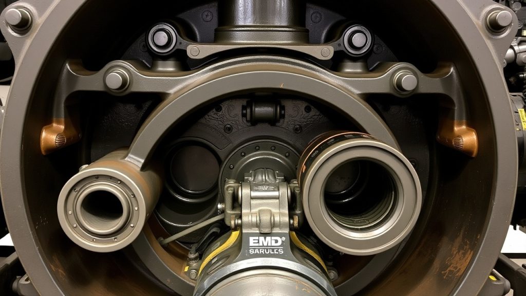
How to Tell When Your EMD Generator Bushings Have Failed
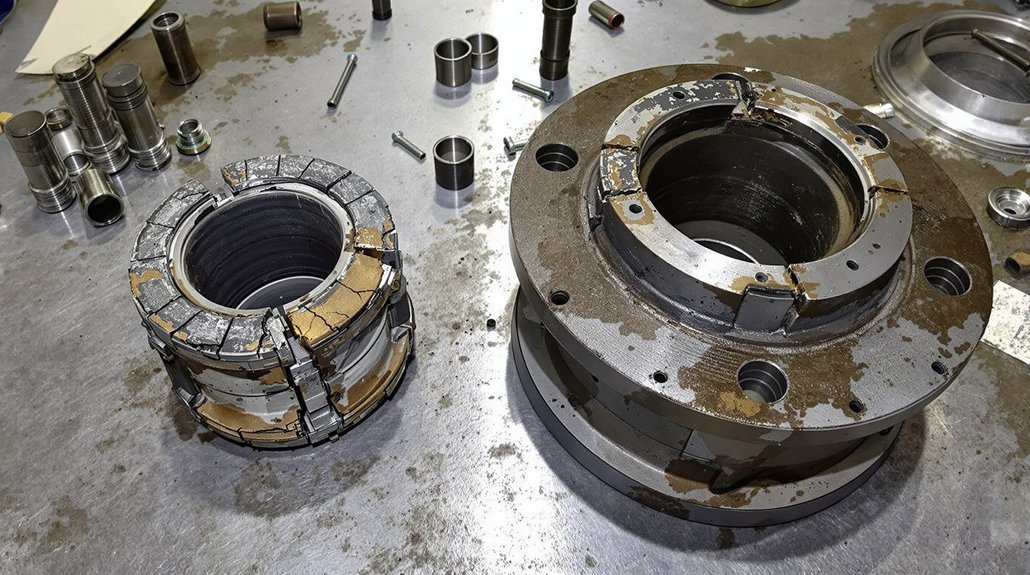
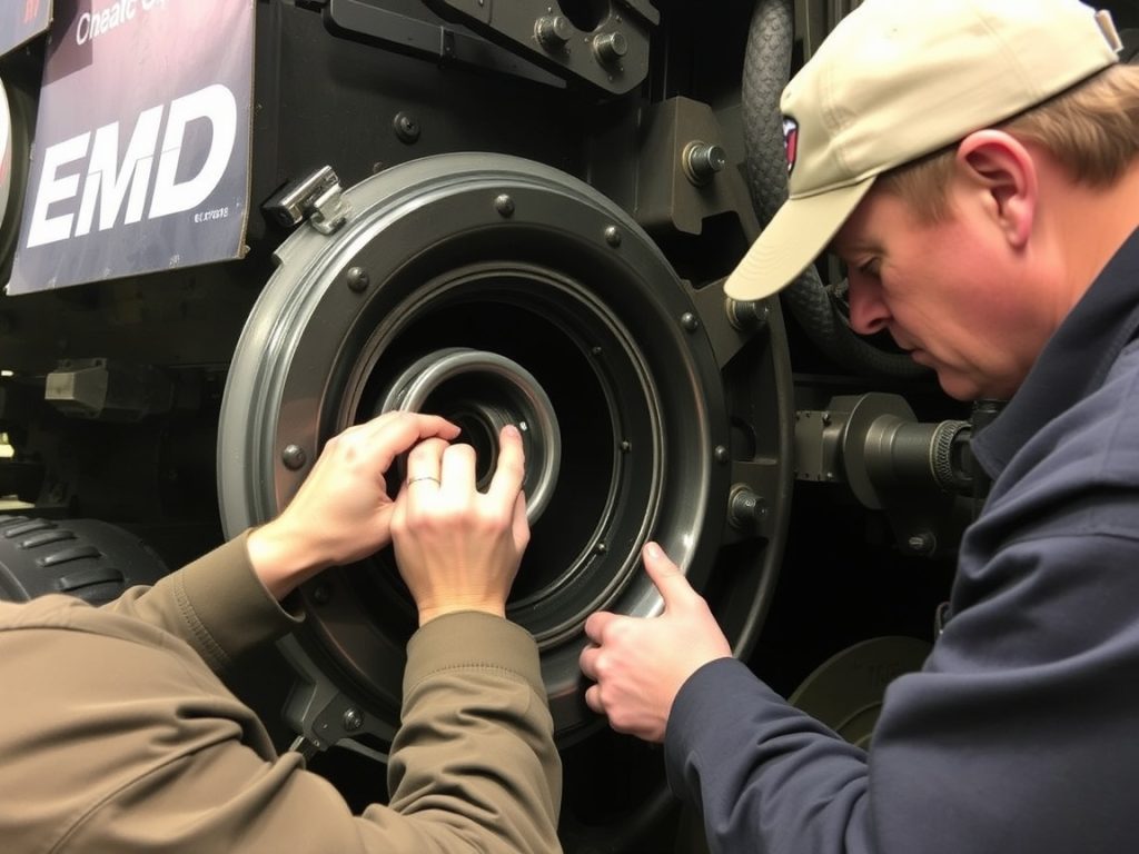
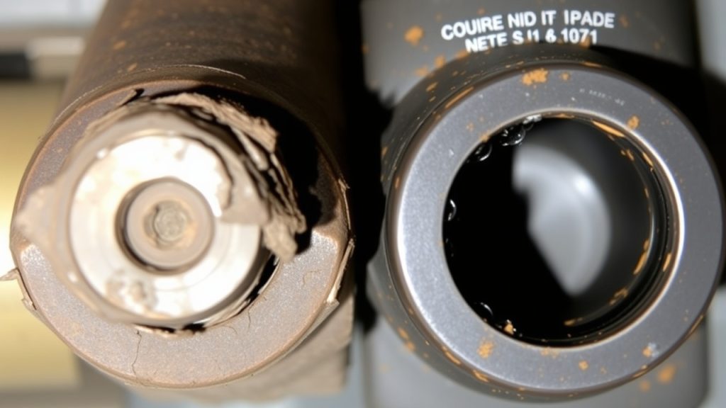
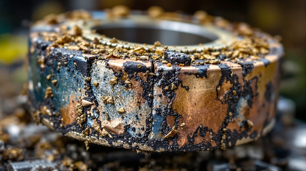
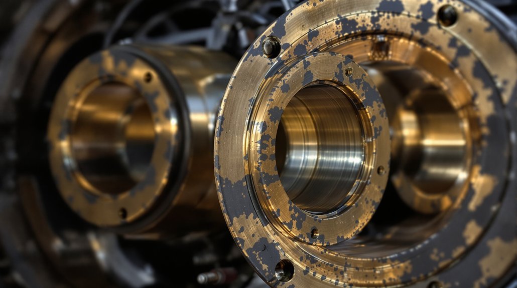
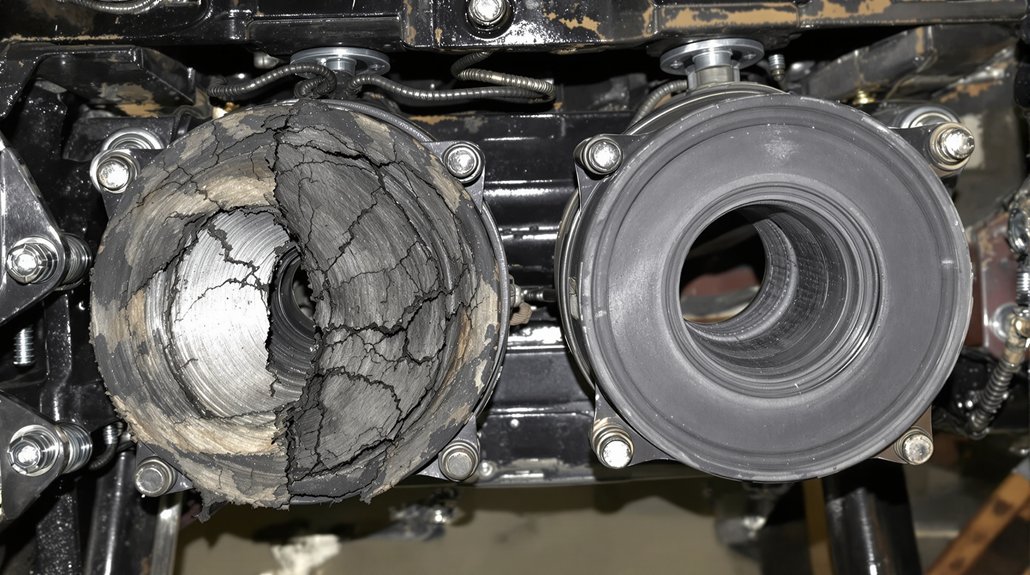
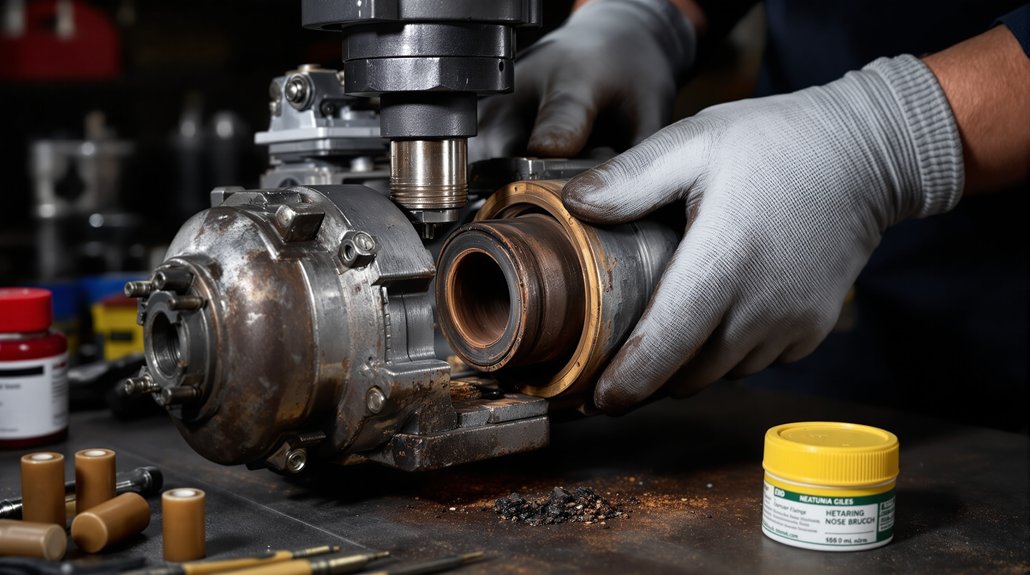
Worn or failed EMD generator coupling bushings typically show up through a distinct set of symptoms that you can identify through visual inspection, sound analysis, and performance monitoring. Start by checking for visual wear on the bushing surfaces — look for cracking, deformation, or material loss around the coupling interface. These indicators confirm degradation that’s already affecting mechanical integrity.
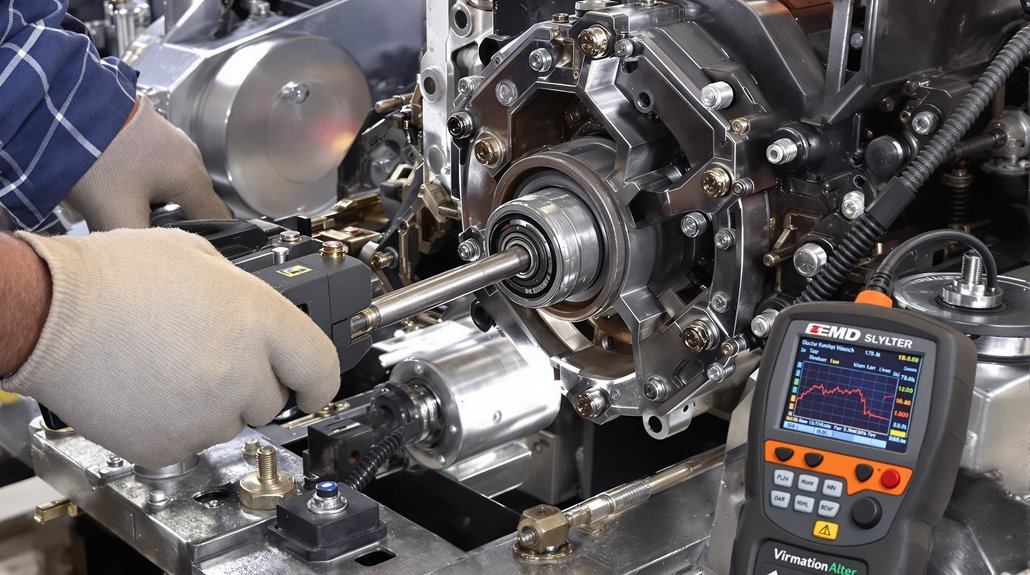
Next, monitor for noise increase during operation. A failing bushing transmits abnormal vibration through the drivetrain, producing rhythmic knocking or irregular thumping sounds that intensify under load. Don’t dismiss subtle acoustic changes; they’re early failure warnings you can’t afford to ignore.
You should also track generator output consistency. Coupling bushing failure introduces rotational instability, which disrupts power transfer and causes voltage fluctuation. If you’re seeing erratic electrical output alongside physical wear signs and elevated noise levels, replace the bushings immediately before secondary drivetrain damage occurs.
Choose EMD Generator Bushing Kits by Compatibility and Load Rating
Before selecting an EMD generator bushing kit, you’ll need to confirm two non-negotiable criteria: dimensional compatibility with your specific locomotive model and a load rating that matches your drivetrain’s torque demands.
Selecting an EMD generator bushing kit starts with two non-negotiables: dimensional compatibility and a load rating matched to your torque demands.
Cross-reference these parameters before purchasing:
Model compatibility: Verify bushing bore diameter, outer diameter, and length against your locomotive’s OEM specifications
Load rating: Match the bushing’s dynamic load capacity to your generator’s continuous torque output
Material grade: Confirm the elastomer durometer rating suits your operational temperature range
Interference fit tolerance: Validate the press-fit specification against your coupling hub’s machined bore
Service cycle alignment: Select kits rated for your locomotive’s duty cycle, whether light switching or heavy mainline operations
Mismatched load ratings accelerate fatigue failure, while incorrect model compatibility creates misalignment that transfers harmful stress to generator bearings. Always pull your locomotive’s maintenance manual and confirm specifications before finalizing your kit selection.
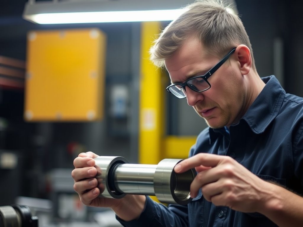
Install EMD Coupling Bushings Without Damaging the Generator
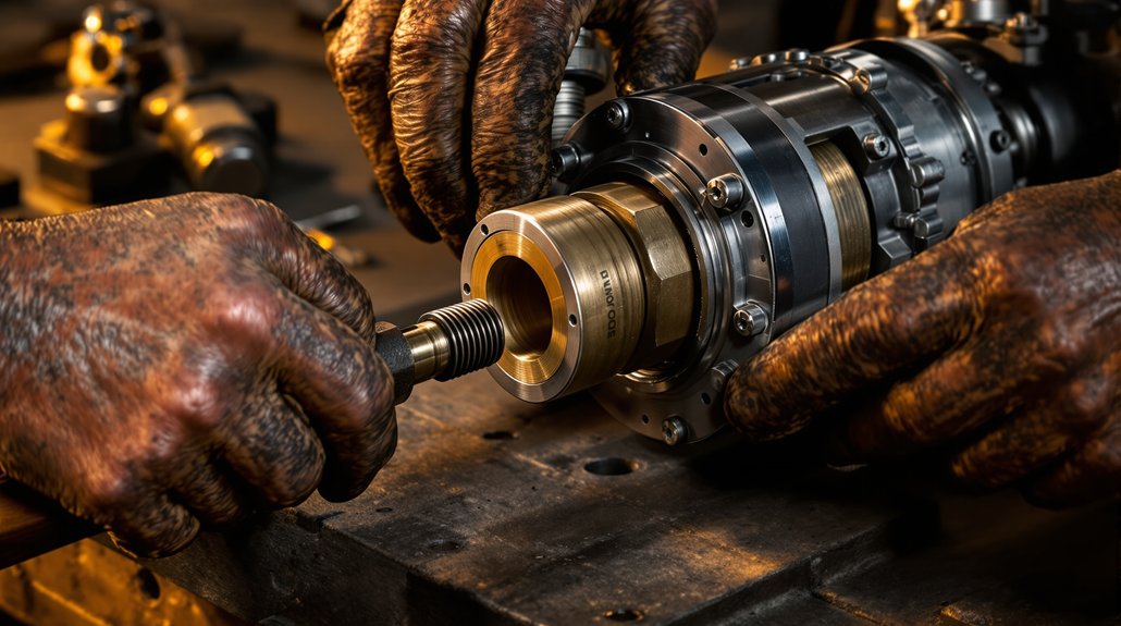
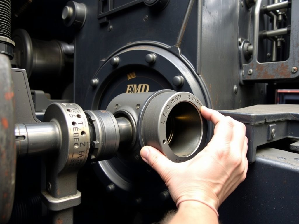
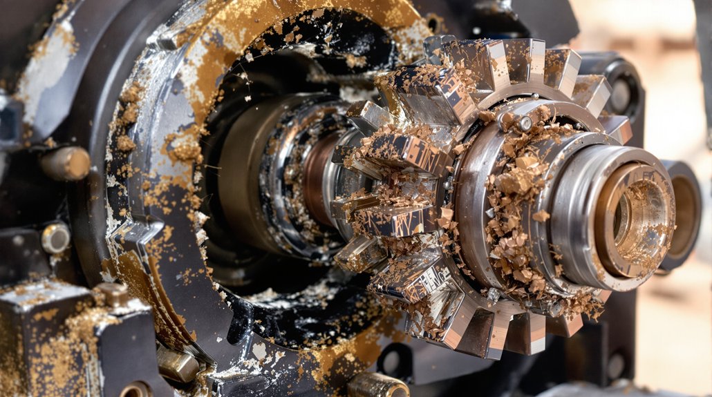
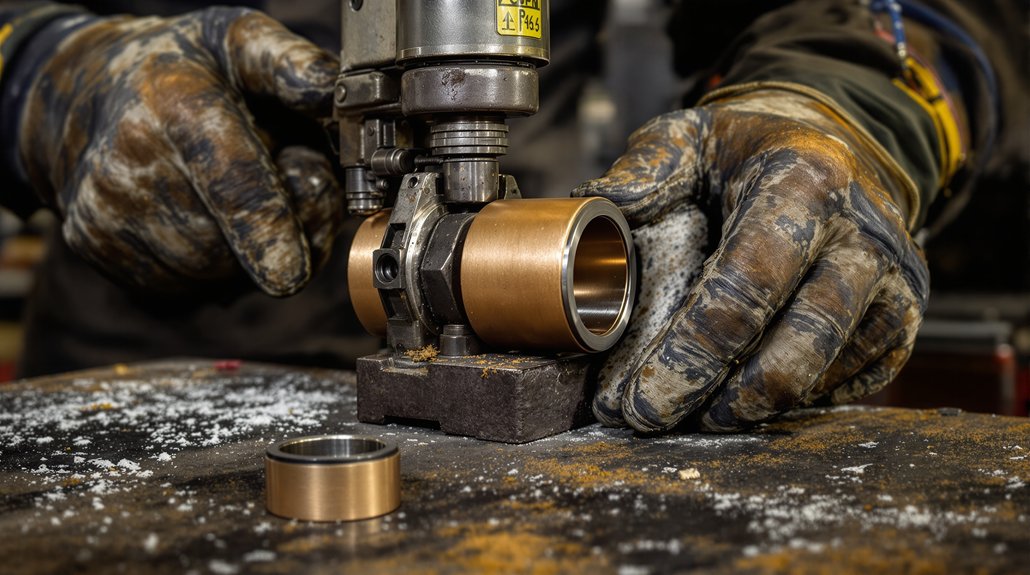
Correct installation technique protects both the bushing and generator from damage that’s difficult and expensive to reverse. Before pressing any bushing into position, verify proper alignment between the bushing bore and the generator coupling housing. Misalignment during installation creates uneven stress that cracks the housing or distorts the bushing wall.
Always use soft mandrels when pressing bushings into place. Steel-on-steel contact concentrates force unevenly and gouges seating surfaces, compromising the interference fit you need for reliable power transfer. Soft mandrels distribute pressing force evenly across the bushing flange, preventing deformation.
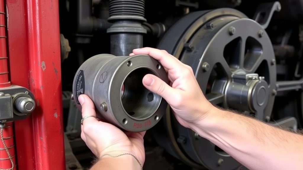
Apply a light film of assembly lubricant to the outer diameter before pressing. Check seating depth with a dial indicator after installation—an improperly seated bushing shifts under load and accelerates wear on both the coupling and generator shaft. Never use heat on the generator housing unless the manufacturer explicitly specifies it.
Frequently Asked Questions
How Long Do EMD Locomotive Generator Coupling Bushings Typically Last?
EMD locomotive generator coupling bushings typically last between 500,000 and 1,000,000 miles under normal operating conditions, though service intervals vary based on load cycles and maintenance practices. You’ll need to monitor replacement frequency closely, as heavy-haul applications accelerate wear markedly. You should inspect bushings during every major overhaul, typically every 18–24 months, and replace them when clearances exceed manufacturer tolerances to prevent generator misalignment.
What Materials Are EMD Generator Coupling Bushings Commonly Made From?
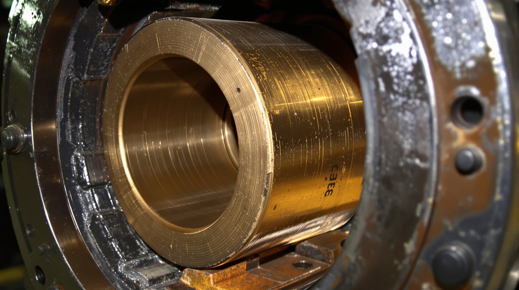
You’ll find EMD generator coupling bushings commonly manufactured from bronze alloys or composite polymers. Bronze alloys offer superior thermal conductivity and wear resistance under heavy mechanical loads, making them ideal for high-torque applications. Composite polymers, however, provide excellent vibration dampening and corrosion resistance in moisture-prone environments. When selecting your bushing material, you’ll need to evaluate your locomotive’s operational demands, load cycles, and environmental conditions to determine the most appropriate composition.
Can Worn Bushings Cause Fuel Efficiency Problems in EMD Locomotives?
Yes, worn bushings absolutely tank your fuel efficiency—it’s like running a steam-age machine in a modern fleet. When bushings degrade, you’ll experience misalignment between the engine and generator, forcing the prime mover to work harder. This inefficiency creates reduced power output, meaning your engine compensates by burning more fuel. Additionally, incomplete combustion cycles trigger increased emissions, compounding both your operational costs and environmental compliance concerns.
Are EMD Generator Bushing Kits Covered Under Any Warranty Programs?
It’s not a one-size-fits-all situation — warranty coverage varies by supplier. You’ll typically find that OEM-certified EMD generator bushing kits carry manufacturer-backed warranties, covering defects in materials and workmanship. Additionally, you can secure extended protection through service contracts offered by authorized distributors. Always review contract terms carefully, confirming coverage durations, exclusions, and replacement procedures before committing to guarantee your components remain operationally compliant and protected.
The High Cost of Downtime: Why EMD Engine Parts Matter
Every minute your EMD 645 or 710 engine sits idle translates directly into lost revenue, missed schedules, and mounting operational costs. Whether you’re managing a locomotive fleet or maintaining marine vessels, sourcing quality replacement parts quickly becomes your most critical challenge. The struggle intensifies when you need components that match OEM specifications while avoiding counterfeit parts that could catastrophically fail under load.
Common challenges maintenance professionals face include:
Unpredictable lead times causing extended downtime and schedule disruptions
Quality inconsistencies between suppliers leading to premature failures
Compatibility issues with aftermarket components
Excessive inventory costs from overstocking to avoid stockouts
Limited supplier transparency about parts authenticity and manufacturing standards
Technical documentation gaps making proper installation difficult
Rising costs from emergency sourcing and expedited shipping
Warranty considerations when mixing OEM and aftermarket components
Understanding EMD 645 and 710 Engine Architecture
The EMD 645 and 710 series engines represent decades of proven engineering excellence in locomotive and marine applications. The 645 series, introduced in 1965, revolutionized rail transportation with its robust two-stroke diesel design, while the 710 series followed in 1984 with improved efficiency and power output. Both engines share fundamental design principles but feature distinct specifications that demand precise component matching.
These powerplants operate under extreme conditions—constant vibration, thermal cycling, and sustained high-load operation—making component quality non-negotiable. Understanding the fundamental differences between these engines helps procurement specialists make informed decisions. The 645 features a displacement of 645 cubic inches per cylinder, while the 710 increased this to 710 cubic inches, requiring larger bore diameters and modified component geometries. This distinction becomes critical when sourcing EMD 645 parts or EMD 710 parts, as interchangeability remains limited despite visual similarities.
Critical Wear Components: What Fails First and Why
Certain components in EMD engines experience accelerated wear due to operational stresses. Cylinder liners face constant pressure from combustion forces and piston movement, gradually wearing beyond acceptable tolerances. This wear pattern manifests as increased oil consumption, reduced compression, and declining power output—symptoms every marine and locomotive engineer recognizes immediately.
Valve guides and valves themselves endure extreme temperatures and constant mechanical stress, making them among the most frequently replaced items. When exhaust valves lose their seating integrity, combustion gases escape, causing efficiency losses and potential head damage. Similarly, crankshaft bearings carry the entire engine’s rotational loads, operating in oil-film conditions that demand precise clearances. As these EMD crankshaft bearings wear, vibration increases, oil pressure drops, and catastrophic failure risk escalates. Recognizing these wear patterns allows maintenance teams to implement predictive replacement strategies rather than reactive emergency repairs.
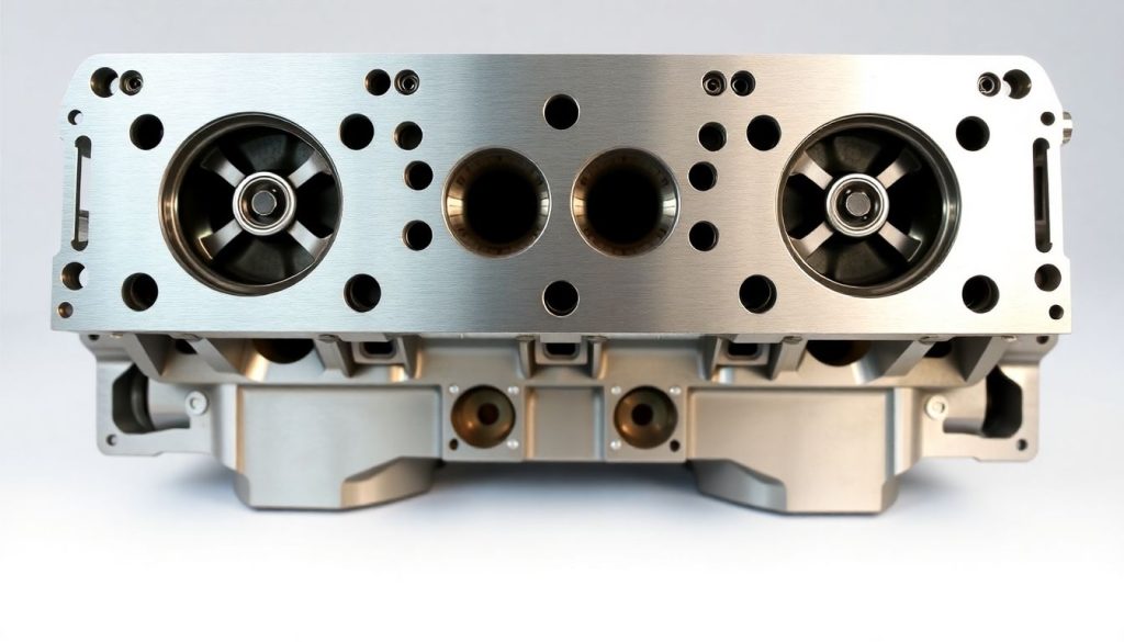
Cylinder Heads for EMD: The Foundation of Engine Performance
Cylinder heads represent one of the most complex and critical components in EMD 645 and 710 engines. These castings must withstand extreme thermal stress while maintaining precise valve seating, coolant passages, and combustion chamber geometry. When sourcing cylinder heads for EMD applications, specifications matter tremendously—material composition, heat treatment, and machining tolerances directly impact longevity and performance.
Quality cylinder heads feature proper metallurgy to resist thermal cracking, precisely machined valve seats that maintain compression over thousands of operating hours, and coolant passages designed for optimal heat dissipation. Inferior castings may initially appear acceptable but develop micro-cracks under thermal cycling, leading to coolant contamination of lubricating oil or loss of compression. When evaluating suppliers as an OEM locomotive parts supplier, verification of manufacturing processes and material certifications becomes essential. The best cylinder heads undergo magnetic particle inspection and pressure testing before delivery, ensuring they meet or exceed original specifications.
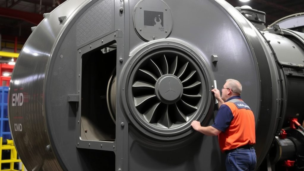
Turbocharger Systems: Maximizing Power and Efficiency
Turbochargers EMD 645 and 710 applications must deliver consistent boost pressure across varying load conditions and ambient temperatures. These precision instruments contain components spinning at extraordinary speeds—compressor wheels rotating above 100,000 RPM—requiring perfect balance and clearance control. When turbocharger performance degrades, engine response suffers, fuel consumption increases, and exhaust temperatures rise beyond acceptable limits.
Modern replacement turbochargers incorporate advanced materials and coatings that extend service life beyond original components. However, compatibility verification remains crucial—differences in housing dimensions, bearing systems, and actuator mechanisms between 645 and 710 applications prevent interchangeability. Successful turbocharger replacement requires matching compressor and turbine wheel specifications, verifying bearing clearances, and ensuring proper oil supply and return line configurations. Professional maintenance operations maintain detailed turbocharger performance logs, tracking boost pressure, exhaust temperature, and compressor efficiency to predict replacement timing and avoid unexpected failures during critical operations.
Valve Components: Precision Parts for Reliable Operation
The valve train in EMD engines operates with military precision, opening and closing valves thousands of times per minute while maintaining exact timing. EMD valve guides replacement becomes necessary when valve stem clearances exceed specifications, allowing excessive lateral movement that accelerates wear on valve stems and seats. This seemingly minor issue cascades into major problems—burned valves, loss of compression, and eventual head damage.
Premium valve guides feature bronze or specialized alloy construction with precise inside diameter tolerances and proper length dimensions. Installation requires careful attention to press-fit specifications and alignment with valve seats. Similarly, valve replacement demands consideration of material composition, stem diameter, face angle, and overall length. Marine applications particularly benefit from materials resistant to sulfur corrosion from heavy fuel oils, while locomotive applications prioritize resistance to thermal fatigue. When you buy EMD engine spares, verifying these specifications prevents costly rework and ensures long-term reliability.
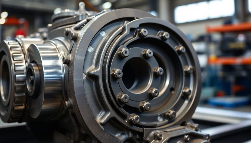
Bearing Systems: Supporting Rotating Assemblies
Crankshaft and connecting rod bearings in EMD engines operate under extreme loads while maintaining thin oil films that prevent metal-to-metal contact. These precision-manufactured components feature multiple layers—a steel backing for strength, a bronze or aluminum intermediate layer for load distribution, and a specialized overlay for conformability and seizure resistance. When bearings fail, consequences range from increased vibration to complete engine destruction.
EMD crankshaft bearings require exact thickness specifications to maintain proper clearances—too tight restricts oil flow and causes overheating, too loose allows excessive movement and triggers fatigue failures. Modern bearings often incorporate improved overlay materials that enhance resistance to contamination and extend service intervals. Procurement specialists must verify bearing dimensions, material specifications, and compatibility with specific engine serial number ranges, as EMD implemented running changes throughout production runs. Quality suppliers provide detailed cross-reference information and technical support to ensure locomotive parts compatibility across different engine variants and rebuild specifications.
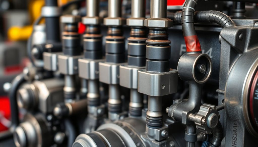
Fuel System Components: Ensuring Clean, Efficient Combustion
Fuel injectors and related components directly impact combustion efficiency, emissions, and power output. These precision instruments meter fuel delivery with extreme accuracy, atomizing fuel for optimal mixing with compressed air. Over time, injector nozzles wear, spray patterns degrade, and fuel delivery becomes inconsistent across cylinders, resulting in rough operation, black smoke, and reduced efficiency.
Replacement fuel system components must replicate original spray patterns, delivery pressures, and flow rates. Quality injectors undergo flow bench testing to verify performance before shipment. Additionally, fuel pumps, filters, and lines require attention during maintenance intervals. Marine applications face particular challenges from fuel quality variations and contamination, making robust filtration and regular component inspection critical. Understanding these systems helps maintenance teams schedule preventive replacements rather than reacting to failures that could sideline equipment during peak operational periods.
Cooling System Components: Managing Thermal Loads
Effective cooling system operation prevents thermal damage while maintaining optimal operating temperatures. Water pumps, thermostats, and oil coolers work together managing heat loads generated by combustion and friction. When cooling system components degrade, engine temperatures climb, leading to accelerated wear, potential head warping, and even catastrophic failure if operators don’t catch problems quickly.
Oil coolers deserve special attention because they prevent lubricating oil from breaking down under thermal stress. These heat exchangers feature internal tube bundles and baffles that maximize heat transfer efficiency. When tubes develop leaks, coolant contaminates lubricating oil—a condition requiring immediate attention to prevent bearing damage. Replacement coolers must match original heat transfer capacity and pressure drop characteristics. Similarly, water pumps require proper impeller design, seal integrity, and bearing support. Quality lubrication/oil coolers maintain precise temperature control across varying load conditions, extending oil change intervals and protecting internal components.
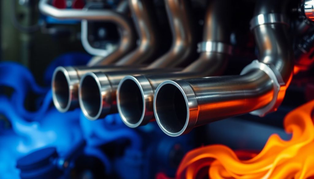
Exhaust System Components: Handling High-Temperature Gases
Exhaust manifolds, gaskets, and related components endure extreme thermal stress and corrosive exhaust gases. These components must resist thermal expansion while maintaining gas-tight seals that prevent exhaust leaks. When exhaust system integrity fails, consequences include reduced power, increased backpressure, and potential safety hazards from hot gas leaks.
Quality exhaust manifolds feature proper material selection and reinforcement designs that resist cracking under thermal cycling. Gaskets require specialized materials that maintain sealing ability across temperature extremes—from cold startup to full-load operation. Marine applications particularly demand corrosion resistance from sulfur compounds in exhaust gases. When selecting exhaust components, verification of material specifications and dimensional accuracy ensures long-term reliability. Professional operations maintain exhaust system inspection schedules, checking for cracks, warping, and gasket integrity before small issues become major failures.
Strategic Sourcing: Finding Reliable Parts Suppliers
Identifying trustworthy suppliers requires evaluation beyond price considerations. Quality suppliers demonstrate deep technical knowledge, maintain comprehensive inventory, and provide detailed documentation. They understand locomotive parts compatibility across different engine variants and offer technical support for complex installations. Fast delivery locomotive spares capabilities separate exceptional suppliers from mediocre ones—emergency situations demand responsive partners who maintain adequate stock levels.
Mikura International has established itself as a leading OEM locomotive parts supplier by maintaining extensive inventory of critical components and providing technical expertise that helps customers make informed decisions. When evaluating any supplier, verify their quality control processes, request material certifications, and assess their technical support capabilities. The best partnerships develop through consistent performance—reliable quality, accurate documentation, and responsive communication. Rather than sourcing from multiple vendors, consolidating purchases with proven suppliers streamlines procurement, reduces inventory complexity, and ensures consistent quality standards.
Counterfeit and substandard parts pose serious risks in locomotive and marine applications. These components may appear identical to genuine parts but fail prematurely due to inferior materials, improper heat treatment, or dimensional inaccuracies. Implementing robust quality verification processes protects against these risks while ensuring operational reliability.
Request material certifications, dimensional inspection reports, and manufacturing process documentation from suppliers. Quality components arrive with proper packaging, clear part number identification, and technical documentation. Visual inspection reveals quality—precision machining, proper surface finishes, and appropriate markings distinguish genuine components from counterfeits. When you buy EMD engine spares, insisting on documentation and verification protects your investment and prevents costly failures. Established suppliers understand these requirements and willingly provide comprehensive documentation supporting component authenticity and quality standards.
Inventory Management: Balancing Availability and Cost
Effective spare parts inventory management balances the cost of carrying inventory against downtime risks from stockouts. Critical components like cylinder heads for EMD applications, turbochargers, and bearing sets deserve priority stocking due to their long lead times and operational importance. Less critical items with shorter lead times can operate under just-in-time procurement strategies.
Computerized inventory systems track consumption patterns, predict replacement timing, and trigger reorder points automatically. Smart maintenance operations analyze historical failure data, identifying components requiring proactive replacement before failures occur. This predictive approach reduces emergency sourcing costs while minimizing downtime. Partnering with suppliers offering fast delivery locomotive spares capabilities provides additional flexibility, allowing reduced on-site inventory while maintaining quick response to unexpected failures. Regular inventory audits verify physical counts match system records, preventing surprises when critical components are needed urgently.
Conclusion: Building Reliable Supply Chains
Success in locomotive and marine engine maintenance depends on reliable access to quality spare parts. Understanding component specifications, identifying trustworthy suppliers, and implementing strategic inventory practices creates operational resilience. The EMD 645 and 710 engines deliver decades of reliable service when supported by proper maintenance and quality replacement components.
Mikura International stands ready to support your operational needs with comprehensive inventory, technical expertise, and commitment to quality. By focusing on OEM-specification components, maintaining extensive stock, and providing responsive customer service, we help maintenance professionals minimize downtime and maximize equipment reliability. The investment in quality parts and reliable supply partnerships pays dividends through reduced failures, extended component life, and improved operational efficiency.
The EMD 645 is a series of diesel engines that has powered railway locomotives and marine applications for decades. Understanding the engine parts, especially when sourcing aftermarket components from reputable manufacturers, is crucial for maintaining optimal performance and longevity. Let’s delve into the world of EMD 645 locomotive engine parts.
Overview of EMD 645 Locomotive Engine Parts
Introduction to EMD Locomotive Engines
Electro-Motive Diesel (EMD), a division of Progress Rail, is renowned for its powerful and reliable locomotive engines. The EMD 645 engine, a product of the electro-motive division, is a prime example of their engineering prowess, serving as a workhorse in railway locomotives and marine vessels. The EMD engines set the standard for power in the locomotive industry.
Importance of Quality Engine Parts
The quality of engine parts directly impacts the performance and lifespan of the EMD 645 locomotive engine. Using certified, high-quality aftermarket parts, like precision-engineered bushings from top manufacturers, ensures that the engine operates efficiently and reliably. Mikura International is the best supplier that offers high-quality locomotive parts from reputable manufacturers and helps avoid costly breakdowns while maintaining optimal power output. Choosing the right locomotive parts from trusted brands will increase the lifespan of your locomotive.
Key Features of the EMD 645 Engine
The EMD 645 is a two-stroke diesel engine known for its robust design and ease of maintenance. Available in various configurations, including turbo and non-turbo versions, the 645 engine offers a versatile power solution for different applications. When seeking EMD 645 engine parts, it’s important to consider the specific features of your engine to ensure compatibility. Mikura International provides a wide range of EMD 645 engine parts, including those from the electro-motive division.
The EMD 645 is a series of diesel engines that has powered railway locomotives and marine applications for decades. Understanding the engine parts, especially when sourcing aftermarket components, is crucial for maintaining optimal performance and longevity. Let’s delve into the world of EMD 645 locomotive engine parts.
Overview of EMD 645 Locomotive Engine Parts
Introduction to EMD Locomotive Engines
Electro-Motive Diesel (EMD), a division of Progress Rail, is renowned for its powerful and reliable locomotive engines. The EMD 645 engine is a prime example of their engineering prowess, serving as a workhorse in railway locomotives and marine vessels. The EMD engines set the standard for power in the locomotive industry.
Importance of Quality Engine Parts
The quality of engine parts directly impacts the performance and lifespan of the EMD 645 locomotive engine. Using certified, high-quality aftermarket parts, like precision-engineered bushings, ensures that the engine operates efficiently and reliably. Mikura International is the best supplier that offers high-quality locomotive parts and helps avoid costly breakdowns and maintain optimal power output. Choosing the right locomotive parts will increase the lifespan of your locomotive.
Key Features of the EMD 645 Engine
The EMD 645 is a two-stroke diesel engine known for its robust design and ease of maintenance. Available in various configurations, including turbo and non-turbo versions, the 645 engine offers a versatile power solution for different applications. When seeking EMD 645 engine parts, it’s important to consider the specific features of your engine to ensure compatibility. Mikura International provides a wide range of EMD 645 engine parts.
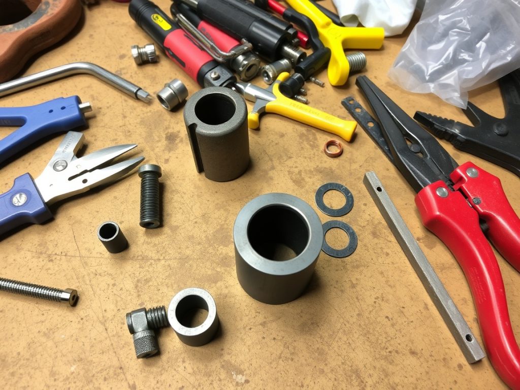
Understanding Bushings in Locomotive Engines
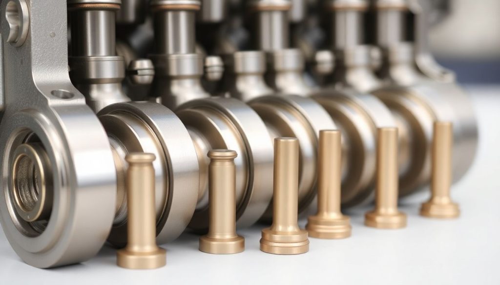
What are Bushings?
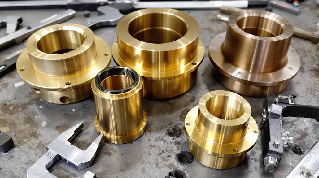
Bushings are crucial engine parts in Electro-Motive locomotive engines, serving as interface components that reduce friction and wear between moving surfaces. These cylindrical or flanged parts, often made of bronze or other durable materials, are integral to the smooth operation of various EMD locomotive systems, like the EMD 645, where they support rotating shafts and absorb vibrations. Bushings can extend the life of the product, so choose wisely.
Role of Bushings in Engine Performance
The role of bushings is vital for maintaining the performance and reliability of EMD locomotive engines. By minimizing friction and wear, bushings enable smoother movement of engine parts, ensuring efficient power transmission and reducing the risk of mechanical failure. Proper bushing maintenance contributes to optimal performance, extending the service life of the entire locomotive engine, including the EMD 710 engines. Mikura International offers a range of EMD bushings.
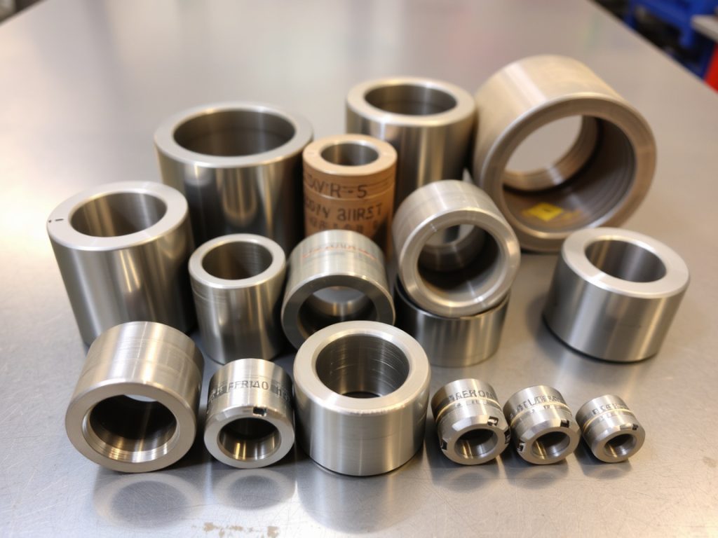
Types of Bushings for EMD 645
For the EMD 645 locomotive engine, different types of bushings are used depending on the application. These may include crankshaft bushings, connecting rod bushings, and piston pin bushings. It’s essential to select the correct bushing type from a reliable manufacturer to ensure proper fit and function and improve the quality of the locomotive. Bushings are parts in stock at Mikura International.
Aftermarket Parts for EMD Locomotive Engines
Benefits of Choosing Aftermarket Parts
Choosing aftermarket parts for EMD locomotive engines can offer several benefits. Aftermarket locomotive parts often provide a cost-effective alternative to OEM parts while maintaining comparable quality and performance. Additionally, aftermarket suppliers may offer a wider range of options and improved availability, ensuring that locomotive owners can quickly source the parts they need for repairs and maintenance. Mikura International is the best aftermarket supplier.
Top Aftermarket Suppliers
When sourcing aftermarket EMD locomotive parts, it’s important to consider reputable manufacturers known for their quality and reliability. Some top aftermarket suppliers include companies specializing in EMD 645 and EMD 710 engines and components. These suppliers offer a comprehensive range of engine parts, including bushings, pistons, and cylinder heads, ensuring that locomotive owners can find the parts they need for their specific engine models. Mikura International offers only certified parts.
Mikura International: Your Key Supplier
Mikura International stands out as your key supplier for aftermarket EMD locomotive parts. With a focus on quality, reliability, and customer satisfaction, Mikura International offers a comprehensive range of parts specifically designed for EMD 645 and EMD 710 engines. Whether you need bushings, bearings, or other essential engine components, Mikura International provides the products and service you can rely on to keep your EMD locomotive running smoothly. Mikura International provides fast shipping.
Exploring EMD Bearings and Their Significance
Types of EMD Bearings
EMD bearings are vital electro-motive components that ensure smooth and efficient locomotive engine operation, enhancing overall industrial performance. Different types of EMD bearings, manufactured by the electro-motive division, cater to specific needs, including roller bearings, ball bearings, and plain bearings. Each type of EMD bearing provides unique advantages in terms of load capacity, speed capability, and durability, ensuring optimal performance for EMD locomotive parts. Mikura International is the best place to get locomotive bearings from a trusted brand.
Impact of Bearings on Engine Longevity
The quality and maintenance of EMD bearings significantly impact the overall longevity of the locomotive engine. High-quality EMD bearings minimize friction and wear, reducing the risk of premature engine failure and extending its service life. Regular inspection and timely replacement of worn or damaged bearings are essential for maintaining optimal engine performance and preventing costly breakdowns. Mikura International offers high-quality products.
Choosing the Right Bearings for Your Locomotive
Selecting the right EMD bearings for your locomotive requires careful consideration of several factors, including the engine model, operating conditions, and load requirements. Consulting with experienced electro-motive professionals and referring to the electro-motive manufacturer’s specifications can help ensure you choose the appropriate bearings for your specific application. Mikura International provides the best EMD 645 locomotive parts with fast shipping.
Conclusion: Ensuring Reliability in Locomotive Operations
Summary of Key EMD Parts
In summary, maintaining the reliability of EMD locomotive operations depends on the quality and proper maintenance of key EMD parts. These parts include bushings, bearings, and other essential engine components. Opting for high-quality aftermarket components from trusted suppliers ensures optimal performance and longevity. Mikura International is your key supplier to provide you with the EMD 645 locomotive engine parts, enhancing your industrial operations.
Final Thoughts on Maintenance and Quality Parts
Prioritizing regular maintenance and using quality engine parts are crucial for ensuring the long-term reliability of EMD locomotives. By investing in certified, high-quality aftermarket parts and adhering to recommended maintenance schedules, locomotive operators can minimize downtime, reduce operating costs, and maximize the lifespan of their valuable assets. Choose Mikura International to get the best EMD locomotive parts at competitive prices.
Q: What are the key components of the EMD 645 locomotive engine?
A: The key components of the EMD 645 locomotive engine include the cylinder heads, pistons, crankshaft, turbocharger, fuel injectors, and various gaskets and seals. Each of these parts plays a crucial role in the engine’s performance and efficiency.
Q: Where can I find aftermarket EMD locomotive parts?
A: Aftermarket EMD locomotive parts can be found through specialized suppliers like Mikura International. They offer competitive pricing and a wide selection of parts for maintenance and repair.
Q: What is the function of a bushing in EMD 645 locomotive engines?
A: A bushing in EMD 645 locomotive engines serves as a protective sleeve that reduces friction and wear between moving parts, such as the crankshaft and connecting rods. It ensures smooth operation and longevity of the engine components.
Q: Are there any specific maintenance tips for EMD locomotive parts?
A: Yes, regular maintenance tips for EMD locomotive parts include routine inspections for wear and tear, timely oil changes, monitoring coolant levels, and ensuring that the turbocharger is functioning optimally. Keeping the engine clean also helps prevent premature wear.
Q: How can I identify genuine EMD 645 parts from aftermarket options?
A: To identify genuine EMD 645 parts, look for serial numbers, manufacturer logos, and quality markings. Purchasing from reputable dealers or manufacturers, such as Mikura International, can also help ensure you are getting authentic parts.
Q: What is the role of the turbo in the EMD 645 locomotive engine?
A: The turbo in the EMD 645 locomotive engine increases the engine’s efficiency by forcing more air into the combustion chamber, which allows for a more complete fuel burn. This results in improved power output and fuel economy.
Q: Can I replace EMD locomotive parts with generic alternatives?
A: While it is possible to replace EMD locomotive parts with generic alternatives, it is not always recommended. Using OEM parts ensures compatibility and reliability, whereas generic parts may not meet the same quality standards and could lead to performance issues.
Q: What types of bushing are available for EMD locomotive engines?
A: There are several types of bushings available for EMD locomotive engines, including plain bushings, flanged bushings, and thrust washers. Each type serves a specific purpose and should be chosen based on the application within the engine.
The EMD 710 engine is a powerful and dependable diesel engine used in a multitude of locomotive and marine applications. EMD®, or Electro-Motive Diesel, is a leading manufacturer known for its high-quality products and innovative designs, often setting the standard in the locomotive industry. This article provides a comprehensive overview of EMD 710 engine bearings, critical components that ensure the smooth and efficient operation of these engines.
Overview of EMD Locomotive Components
EMD locomotive parts encompass a vast range of components, forming complex systems integral to the locomotive’s function. These parts include everything from the engine itself to the generator, alternator, and even the turbochargers. The 710 engine is just one model in EMD’s lineup, preceded by the 567 and 645 and followed by later generations.
Introduction to EMD and Its Importance in Locomotives
EMD stands as a cornerstone in the rail equipment and locomotive industry. EMD locomotives have long been the workhorse of railways across the globe, often compared with ALCO models for their reliability. Their diesel engine designs, particularly the 710 engines, provide significant power for moving heavy loads. The EMD locomotive is an icon, integrating innovation and standard configurations to meet the demanding needs of the railway, mining, and industrial markets.
Understanding EMD Bearings and Their Functions
EMD bearings are crucial components within the engine, specifically designed to handle immense loads and torque. These bearings support rotating parts, minimizing friction and wear, and are essential for maintaining the engine’s performance and longevity. An EMD bearing is a vital locomotive part that ensures the dependable operation of the entire unit.
Key Components of EMD Locomotive Parts
Beyond the engine itself, EMD locomotive parts include essential components like valves, turbo units, alternators, and electric systems, all of which require rigorous testing to ensure reliability. These components work in concert to deliver power. The interaction of these locomotive parts influences the efficiency and reliability of the entire system. Replacement part options are available in both OEM quality and aftermarket.
Types of EMD Bearings
Main Bearings for EMD 710 Engines
The main bearings within EMD 710 engines are critical engine parts, as they support the crankshaft, which is the core of the engine, handling the substantial torque generated during the diesel combustion process. These EMD bearings are designed to withstand heavy loads and ensure the smooth rotation of the crankshaft, helping maintain the power output of the engine. Maintenance and timely replacement of these bearings are vital to prevent engine failure. These are locomotive parts that must be in perfect working order.
Valve Bearings and Their Role in Engine Performance
Valve bearings, or valve train components, in EMD 710 engines play a vital role in ensuring proper valve operation. Valves control the intake of air and exhaust of gases, thus optimizing engine performance. These EMD bearings help in reducing friction and wear in the valve mechanism, improving the efficiency and longevity of the engine. The right valve bearings are a locomotive part that ensures the proper functioning of the diesel engine. They also provide optimal sealing and are an integral part of the overall diesel engine assembly.
Comparison of Aftermarket vs. OEM EMD Bearings
When it comes to EMD bearings, the market offers both OEM quality and aftermarket options. OEM EMD bearings are manufactured by EMD® or its certified suppliers, guaranteeing compatibility and performance. Aftermarket EMD bearings, on the other hand, are supplied by third-party manufacturers, which may not always meet the same testing standards as OEM parts. Aftermarket parts may offer cost savings but can vary in quality and durability. When choosing EMD locomotive parts, consider the application, budget, and the criticality of the component; in this case, the bearing, which should be in stock for timely replacement. Genuine OEM parts are always best.
Applications of EMD Locomotive Parts
Utilization in Diesel Electric Locomotives
EMD locomotive parts are extensively used in diesel electric locomotives across various railway systems. These EMD locomotive parts, including the EMD 710 engines, provide the essential power for hauling heavy loads over long distances. The reliability and performance of these components are critical for maintaining efficient railway operations. Because of the demands of the application, the railway is where these locomotives are the most effective.
Role in Marine Engine Applications
Beyond the railway, EMD 710 engines and their respective parts, including EMD bearings, also find applications in marine environments. These diesel engines are used to power ships and boats, providing reliable power for propulsion and other onboard systems. In marine applications, the durability and resistance to corrosion of the EMD parts are essential to withstand harsh conditions. Marine applications are the perfect example of a location where the EMD parts can be implemented.
Performance in Mining and Heavy-Duty Use
EMD locomotive parts, designed for robust performance, are also employed in mining and other heavy-duty industrial applications. EMD 710 engines are adapted to power heavy machinery, providing the necessary torque and reliability for demanding tasks. The mining industry relies on the dependable performance of EMD engines and their components, including standard configurations, to maintain productivity. The design of these engines and parts are compatible with the challenges that arise in the mining industry.
Maintenance and Repair of EMD Bearings
Signs of Wear and Replacement Indicators
Early detection of wear in EMD bearings is key for proactive maintenance. Several indicators can signal a potential issue. These include:
Unusual noises, increased vibrations, or elevated temperatures around the bearing housings.
Excessive play or looseness in the bearings.
Visual inspection might reveal cracks, pitting, or discoloration, all suggesting the need for bearing replacement to avoid major engine failure and ensure that spare parts are readily available. Ignoring these indicators can lead to catastrophic damage to the EMD 710 engines and other locomotive parts, highlighting the importance of regular testing and maintenance.
Best Practices for EMD Bearing Maintenance
Effective EMD bearing maintenance involves implementing a strict schedule of inspections and lubrication. Using the appropriate lubricants, as specified by EMD®, is essential for reducing friction and wear. Keeping the bearing clean and free from contaminants is also vital. Regular monitoring of bearing temperature and vibration levels can help identify potential issues early. Properly maintained EMD bearings contribute to the longevity and reliable performance of EMD 710 engines. The OEM recommends using a quality lubricant to ensure maximum life of the EMD bearings. A genuine component is best to keep the EMD engine running smoothly, ensuring it meets the required standards for performance.
Repair Techniques for EMD Locomotive Components
When EMD locomotive components, including bearings, require repair, specific techniques must be employed. Minor repairs might involve cleaning, polishing, or re-lubricating the bearing to maintain standard performance levels. However, severely damaged bearings must be replaced. Proper installation techniques, including correct torque settings and alignment, are critical to ensure optimal performance and prevent premature failure of components in the configuration.. Specialized tools and trained technicians are often required for complex repairs of EMD 710 engines and related locomotive parts.
Suppliers and Availability of EMD Parts
Identifying Reliable Suppliers for EMD Bearings
Securing EMD bearings from reliable suppliers is paramount for ensuring quality and dependability. It’s important to look for specific characteristics in your suppliers, such as:
Proven track record of providing OEM quality parts.
A warranty on their products and excellent customer service.
It is also important to verify that the EMD 710 engines’ parts from the supplier can handle the torque that the locomotive may output, as some may not be rated for industrial use.
Trusted suppliers like Mikura International are preferred over many local vendors.
Overview of Supply Chain for EMD Locomotive Parts
The supply chain for EMD locomotive parts involves a network of manufacturers, distributors, and service providers. EMD® itself manufactures many critical components, while other parts are sourced from certified suppliers. Distributors play a key role in making these parts available to railway operators and maintenance facilities. Understanding the supply chain helps in identifying potential bottlenecks and ensuring timely availability of replacement parts. The quality of the parts supplied will keep the engine running.
Future Trends in EMD Component Supply
Future trends in EMD component supply are likely to focus on improved efficiency, sustainability, and technology, with an emphasis on stock management of critical parts. There is a growing emphasis on remanufacturing and recycling of EMD parts to reduce waste and environmental impact. Advanced materials and manufacturing techniques are being used to produce more durable and efficient components, setting a new standard in the industry. Digital technologies, such as predictive maintenance and online parts catalogs, are also transforming the EMD parts supply chain by optimizing spare parts management. A dependable supply of EMD 710 engines’ parts will allow the user to keep the equipment in operation.
Q: What types of engine parts are included in the EMD 710 engine bearings product line?
A: The EMD 710 engine bearings product line encompasses a comprehensive range of components that are crucial for the optimal performance of EMD® engines. This includes not only main bearings, which are essential for supporting the crankshaft and ensuring smooth operation, but also connecting rod bearings that play a vital role in enabling the connection between the crankshaft and the engine’s pistons.
Additionally, turbocharger bearings are included in this product line, designed specifically to withstand the high temperatures and pressures associated with turbocharged engine applications. Together, these components are engineered to meet the rigorous demands of EMD locomotives, ensuring reliability and efficiency in various operational conditions.
Q: Are EMD 710 engine bearings compatible with GE generator systems?
A: Yes, EMD 710 engine bearings are compatible with certain GE generator systems, provided they meet the specifications for the engine assembly. This compatibility is crucial for ensuring optimal performance and longevity of the coupling bushings in EMD locomotives’ main generator systems.
Proper alignment and adherence to the specified tolerances are essential to prevent premature wear and maintain efficient operation. When integrating EMD 710 engine bearings into GE generator systems, it is important to consult detailed engineering documentation to ensure that all components work seamlessly together, thereby enhancing the overall reliability and functionality of the locomotive’s power generation capabilities.
Q: What is the power output of the EMD 710 engine compared to the EMD 645 and 567 engines?
A: The EMD 710 engine is renowned for its superior power output compared to its predecessors, the EMD 645 and 567 engines. This enhanced performance makes the EMD 710 the preferred choice for various applications that demand more robust and reliable operation. Whether in freight locomotives or other heavy-duty machinery, the increased efficiency and power of the EMD 710 engine ensure that it meets the rigorous demands of modern transportation and industrial needs.
Q: Where can I find replacement bearings for the EMD 710 engine assembly?
A: Replacement bearings for the EMD 710 engine assembly are available through authorized EMD® distributors and various online retailers specializing in locomotive and marine parts.
Q: Do EMD 710 engine bearings come with a warranty?
A: Yes, most EMD 710 engine bearings come with a manufacturer’s warranty, which covers defects in materials and workmanship under normal operating conditions.
Q: What maintenance is required for the EMD 710 engine bearings and other engine parts?
A: Regular maintenance for EMD 710 engine bearings includes routine inspections, proper lubrication, and ensuring that the engine operates within the recommended temperature and pressure ranges.
Q: Can I use EMD 710 engine bearings in marine applications?
A: Yes, EMD 710 engine bearings are suitable for marine applications, particularly in vessels that require high-performance engine components for reliability and efficiency.
Q: What are the key features of EMD 710 engine bearings that enhance performance?
A: Key features of EMD 710 engine bearings include advanced materials for durability, precision manufacturing for optimal fit, and designs that reduce friction and wear, enhancing overall engine performance.
Q: Are there any specific tools required for the installation of EMD 710 engine bearings?
A: Yes, proper installation of EMD 710 engine bearings may require specific tools such as torque wrenches, bearing pullers, and alignment tools to ensure accurate assembly and operation.
You’ll detect worn traction motor bushings through circumferential scoring marks, axial grooves, and surface pitting on visual inspection. Listen for squealing, grinding, or rhythmic tapping during operation. Monitor for vibration signatures at 80–120 Hz, temperature elevations exceeding 160–180°F at contact points, and voltage ripple above 5%. Measure radial play beyond 0.015 inches or axial movement exceeding 0.010 inches against manufacturer specifications. You’ll observe reduced torque output, current fluctuations approaching 1,200 amperes, and thermal gradients surpassing 15°C between bearing ends—each indicating progressive deterioration that compromises interconnected components throughout your traction system.
Key Takeaways
Circumferential scoring marks, axial grooves, surface pitting, cracking, and compression flattening indicate physical deterioration from excessive movement and stress cycles.
Squealing, grinding, rhythmic tapping, and crackling noises signal metal-to-metal contact and irregular component movement from worn bushings.
Vibration signatures at 80–120 Hz during loaded operations with amplitude increases beyond baseline ~0.3 in/s indicate bushing wear.
Bearing surface temperatures exceeding 95°C and temperature gradients greater than 15°C between bearing ends reveal friction from inadequate clearances.
Shaft misalignment from worn bushings causes eccentric loading, gear tooth imbalance, commutator degradation, and accelerated component deterioration.
Visual Indicators of Bushing Deterioration
When inspecting traction motor bushings during maintenance intervals, you’ll encounter distinct wear patterns that reveal the underlying failure mechanisms. Circumferential scoring marks indicate rotational movement between the bushing and housing, while axial grooves signal excessive longitudinal displacement. Surface pitting demonstrates fatigue damage from repeated stress cycles, and visible cracking on the outer diameter suggests imminent material failure.
You’ll notice surface texture changes where the smooth factory finish becomes roughened through abrasive wear. Visual corrosion appears as water stains or rust products from seal failures and moisture ingress. Discoloration from the original material color indicates thermal degradation, with blue or purple heat tints confirming excessive operating temperatures.
Material delamination manifests as separation of bushing layers or surface flaking. Compression flattening occurs at load points, while bulging exceeds original dimensional specifications. Metal particles embedded in the surface and fretting damage marked by oxidized particles provide definitive evidence of advanced deterioration requiring immediate replacement. Inspection positions should include both drive end and non-drive end locations to ensure comprehensive bushing assessment.
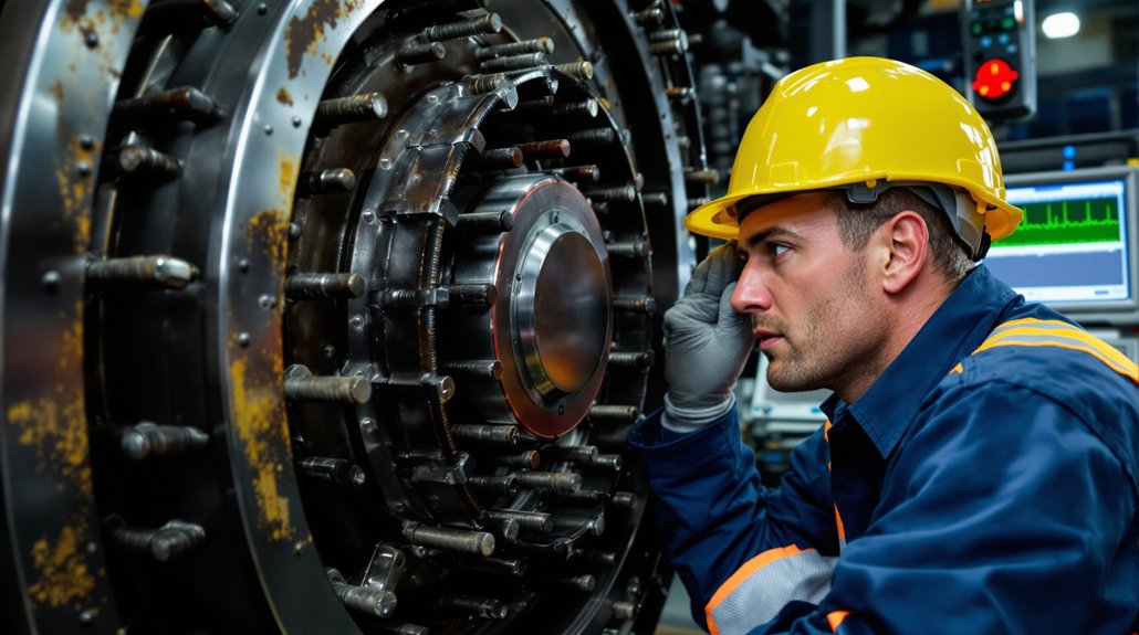
Auditory Warning Signs During Motor Operation
During locomotive traction motor operation, you’ll detect specific acoustic signatures that precede catastrophic bushing failure. Squealing sounds indicate metal-to-metal contact as clearances exceed specifications, while grinding noises signal excessive shaft movement causing irregular component contact. You’ll notice rhythmic tapping from loose bushings permitting shaft oscillation and high-pitched whining from increased friction under load conditions.
Crackling or popping noises reveal electrical arcing caused by misaligned components due to shaft displacement. Buzzing intensifies when connections destabilize from vibration, and sharp snapping occurs during irregular brush contact patterns. Low-frequency rumbling increases with shaft eccentricity, while harmonic resonance develops from loose component frequencies interacting with rotation speeds.
Operator feedback proves critical when identifying alternating pitch variations indicating speed irregularities and surging sounds from binding misaligned components. Acoustic diagnostics enable early detection of pulsating patterns from eccentric shaft rotation and cyclic groaning from inconsistent load paths through deteriorated bushings. Systematic troubleshooting of abnormal sounds involves listening for sounds and correlating them with specific motor operating conditions to pinpoint failing bushings.
Performance Degradation and Efficiency Loss
As bushing wear progresses beyond acceptable tolerances, you’ll measure quantifiable performance losses through vibration amplitude increases and thermal efficiency reductions. RMS signal envelope measurements across 0-200Hz, 0-1kHz, and 0-5kHz frequency bands reveal deteriorating conditions, with 8,096 data points documenting decline patterns. You’ll observe reduced torque output as misaligned bushings cause pitting and scoring on pinion gear teeth, preventing proper meshing.
Energy leakage occurs through increased friction and heat generation from inadequate lubrication, forcing cooling systems to work harder while efficiency drops. Voltage ripple exceeding 5% indicates bearing-related electrical issues, with current fluctuations up to 1200A affecting motor performance. Temperature monitoring reveals overheating patterns from excessive bushing friction, while electrical erosion damages components and reduces overall efficiency. Analyzing these wear patterns against benchmarks enables early detection of bushing degradation before severe damage compromises traction motor reliability. Carpet level envelope spectrum analysis detects degradation even in high-noise environments, enabling you to identify performance decline before catastrophic failure occurs.
Electrical System Irregularities
You’ll detect electrical system irregularities through measurable increases in circuit resistance as worn bushings create poor contact surfaces and contaminated connections. Your monitoring systems will record current asymmetry between traction motors, with faulty units showing markedly lower armature current readings that trigger repeated fault conditions. Voltage anomalies manifest through multimeter testing, revealing interruptions in electrical flow pathways and resistance level deviations that exceed manufacturer specifications. Worn bushings can lead to blown fuses as degraded electrical connections create resistance spikes that exceed circuit protection thresholds.
Increased Resistance and Faults
When traction motor bushings deteriorate, they trigger a cascade of electrical resistance issues that compromise locomotive performance and safety. You’ll observe increased resistance at failure points, particularly where corroded ferrules create high-resistance connections generating excessive heat. Mechanical damage compromises conductors internally, reducing copper cross-section and elevating current density. This deterioration produces arcing hotspots that progressively melt insulation and create ground fault conditions.
Resistance Indicator
Critical Threshold
Voltage ripple levels
>5% abnormal
Current approach to rating
1200A maximum
Combined system losses
16-17% typical
Operating voltage range
600-750V normal
Monitor temperature anomalies, measure resistance across suspected connections, and track efficiency degradation patterns. These measurements reveal developing faults before catastrophic failures occur, enabling preventive maintenance interventions. Loose clamps allow cables to experience excessive cable motion that breaks strands inside the conductor over time.
Current and Voltage Anomalies
Traction motor bushings in deteriorated condition produce measurable electrical anomalies that manifest as voltage instabilities and current imbalances throughout the propulsion system. You’ll observe voltage transients outside the standard 600-750 V operating range, indicating compromised electrical pathways. Current flow deviations from the nominal 1200 A threshold signal degraded connection integrity within motor assemblies. Phase imbalance between motor circuits reveals internal component deterioration requiring immediate attention.
Voltage ripple exceeding 5% produces harmonic distortion that accelerates motor damage. Your monitoring systems will detect ground-fault conditions as worn bushings create unintended electrical paths to chassis ground. Precision instrumentation identifies these anomalies through continuous voltage and current tracking, enabling data-driven maintenance decisions. Connection resistance increases progressively as bushing materials degrade, compromising proper grounding and electrical distribution. Real-time monitoring systems enable immediate corrective actions when electrical irregularities are detected.
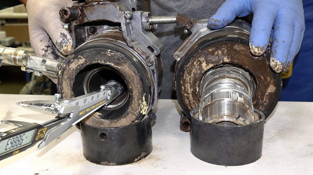
Measurement Deviations During Routine Maintenance
During routine maintenance intervals, you’ll measure bushing clearances against manufacturer specifications, typically finding tolerances exceeded when radial play surpasses 0.015 inches or axial movement exceeds 0.010 inches. Your handheld vibration monitoring systems will detect amplitude increases beyond baseline readings of 0.3 inches per second, correlating directly with bearing surface degradation. You’ll observe temperature elevations exceeding normal operating ranges of 160-180°F at bushing contact points, indicating friction from inadequate clearance maintenance.
Bushing Clearance Tolerance Exceedance
As routine maintenance intervals approach, technicians must verify that bushing clearances remain within manufacturer-specified tolerance bands to prevent bearing assembly failures. You’ll need to evaluate four extreme tolerance combinations when measuring shaft-to-bushing interfaces, accounting for manufacturing variability that creates potential clearance-to-interference variations. Components designed for interference fits may develop clearances due to tolerance accumulation and shaft corrosion effects.
Your measurements should identify whether outer races maintain proper fits with bearing brackets, preventing rotational movement during operation. When clearance fits develop within tolerance ranges, you’ll observe bearing rotation in end frames and inner race creeping. These symptoms indicate insufficient interference maintenance. Calculate extreme dimensional combinations to reveal clearance development, ensuring continuous interference fits prevent slippage and heat generation from sliding friction. Dimensional tolerances are specified in units of micrometers, requiring precision measurement equipment to detect deviations that indicate progressive wear in locomotive traction motor assemblies.
Vibration and Temperature Analysis
Beyond dimensional inspection protocols, measurement deviations in vibration and temperature parameters provide quantitative indicators of bushing deterioration during scheduled maintenance intervals. You’ll observe elevated bearing body temperatures correlating directly with increased vibration impact levels when bushings exceed clearance tolerances. Acoustic monitoring detects surface waviness-induced abnormalities that accelerate fatigue progression in motor bearing races. During routine checks, you must account for operational frequency-dependent heating patterns, as DC-link voltage pulsation at 100 Hz generates thermal elevation in motor hangers.
Temperature readings vary markedly across different vibration conditions, providing diagnostic correlation between bearing failure advancement and amplitude variations. Lubrication effects further influence thermal measurements, requiring standardized assessment protocols that distinguish between normal operational heating and bushing wear-related temperature anomalies during maintenance documentation procedures. Measurement equipment calibration certificates must remain current and traceable to ensure accurate baseline comparisons during successive inspection intervals.
Impact on Adjacent Traction Motor Components
Worn traction motor bushings initiate a cascade of mechanical failures throughout the motor assembly, with armature shaft misalignment representing the most immediate consequence. This misalignment generates eccentric loading patterns that accelerate deterioration across interconnected components.
Deteriorating bushings trigger armature misalignment, creating eccentric loads that systematically compromise adjacent motor components through accelerated mechanical stress propagation.
Progressive Component Damage Sequence:
Bearing Contamination – Excessive bushing clearances allow metallic particles and moisture ingress into bearing assemblies, compromising lubrication integrity and reducing bearing service life by 40-60%.
Commutator Surface Degradation – Shaft misalignment causes uneven brush pressure distribution, creating localized heating zones and accelerated copper wear patterns.
Field Coil Insulation Stress – Increased vibration amplitudes from unstable rotor positioning generate repetitive mechanical stress on field winding insulation, risking thermal breakdown.
Gear Tooth Loading Imbalance – Axial and radial shaft displacement transfers abnormal forces to pinion-gear interfaces, inducing premature tooth pitting and spalling failures. Surface waviness on bearing races compounds these effects by introducing additional vibration frequencies that destabilize the entire traction power transmission system.
Monitor clearance specifications during scheduled inspections to prevent component degradation propagation.
Vibration and Alignment Issues
When traction motor bushings exceed their wear limits, characteristic vibration signatures emerge at frequencies between 80-120 Hz during loaded operations, with peak amplitudes occurring at approximately 100 Hz. You’ll observe shaft harmonics that deviate from baseline patterns as worn bushings allow excessive motor movement, disrupting optimal worm gear meshing geometry.
Misalignment develops when bushings can’t maintain mounting tolerances, creating uneven load distribution across support structures. Your vibration analysis will detect frequency bandwidth expansion and modal behavior shifts as bushing stiffness decreases, altering the assembly’s natural frequency characteristics. Monitoring vibration data trends over time enables detection of sudden changes that may indicate progressive bushing deterioration before complete failure occurs.
Vibration Indicator
Degradation Evidence
Amplitude increases
Exceeds normal operational baselines in specific frequency ranges
Harmonic content changes
Detectable shifts in shaft harmonics and resonance patterns
Alignment deviations
Motor positioning changes affecting geometric relationships
Resonance conditions intensify when meshing frequencies approach the system’s altered natural frequencies, while mechanical looseness generates broader frequency spectra that signal imminent component failure.
Temperature and Thermal Anomalies
Thermal anomalies in traction motor bushings manifest through measurable temperature deviations that exceed the standard 70°C-90°C operating range, signaling friction-induced wear and impending failure. You’ll detect these critical indicators through thermal mapping procedures that reveal localized hot spots at bearing interfaces where degraded bushings create excessive friction.
Critical thermal indicators include:
Bearing surface temperatures exceeding 95°C during normal load conditions, indicating insufficient clearance from bushing wear
Temperature gradients above 15°C between bearing ends, revealing uneven bushing deterioration patterns
Rapid temperature spikes during acceleration cycles that suggest metal-to-metal contact from bushing material loss
Persistent elevated readings despite coolant optimization adjustments, confirming mechanical degradation rather than thermal management issues
You must implement infrared scanning during maintenance intervals to identify developing problems. Thermal imaging technology enables non-contact measurement across motor assemblies, detecting anomalies before catastrophic failure occurs. Temperature monitoring provides quantifiable data for predictive maintenance decision-making.
Frequently Asked Questions
What Is the Typical Lifespan of Locomotive Traction Motor Bushings?
Your locomotive traction motor bushings typically last 10,000+ hours under normal operating conditions, though this varies based on maintenance practices and operational demands. You’ll need to monitor electrical insulation integrity and material hardness degradation throughout service life. Regular lubrication intervals every 92-184 days extend bushing longevity, while inadequate maintenance accelerates wear. You should replace bushings when experiencing unusual vibration, temperature increases, or visible shaft grooving, as these indicate compromised performance standards.
Can Worn Bushings Be Repaired or Must They Always Be Replaced?
When bushings wear beyond specification limits, you’ll face a critical junction. Your repair options include resurfacing bearing surfaces and reconditioning if damage remains within manufacturer tolerances. However, replacement criteria dictate complete substitution when wear exceeds acceptable parameters or cracks appear. You can’t restore severely deteriorated bushings to original specifications—they’ll compromise motor performance and reliability. Cost analysis between repair procedures and genuine replacement parts from authorized suppliers determines your best maintenance approach.
How Much Does Replacement of Traction Motor Bushings Typically Cost?
You’ll find traction motor bushing replacement costs vary markedly based on locomotive type and repair facility. Labor costs typically range from $500-2,000 per motor, depending on accessibility and whether you’re removing the entire motor for bench work. Parts sourcing affects pricing substantially—OEM bushings cost $50-300 each, while bronze or composite aftermarket options may reduce expenses. You’ll need to factor in potential armature machining if wear’s excessive.
What Preventive Maintenance Practices Extend Bushing Service Life Most Effectively?
You’ll extend bushing service life most effectively through regular lubrication using manufacturer-specified products applied at 184-day intervals. Implement vibration monitoring systems to detect early wear patterns before failure occurs. You should maintain strict cleanliness protocols, removing metallic debris and contaminants during scheduled inspections. Combine thermal imaging with ultrasonic testing to identify developing issues. This integrated approach can reduce maintenance costs by 15% while improving asset availability by 25%.
Are Certain Locomotive Models More Prone to Bushing Wear Than Others?
You’ll find older models with axle-hung designs demonstrate higher bushing wear rates due to direct exposure to track irregularities and unsprung mass dynamics. These configurations transmit full track forces through motor bushings, accelerating degradation. Nose-suspended motors experience 40-60% more bushing stress compared to frame-mounted designs. GE D77 and EMD D87 series motors, common in first-generation diesels, require more frequent bushing replacement than modern AC traction systems with improved isolation characteristics.
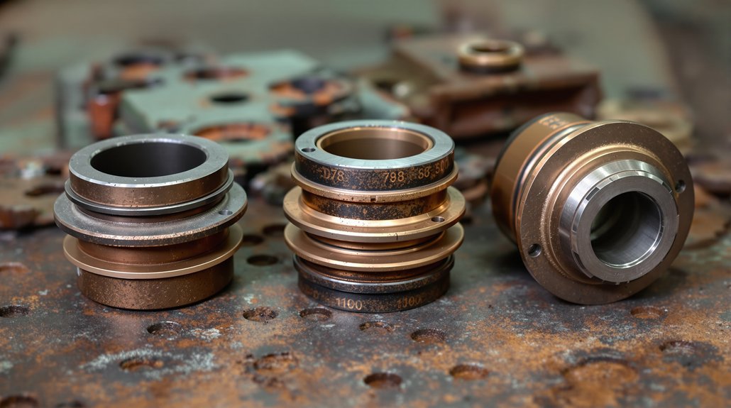
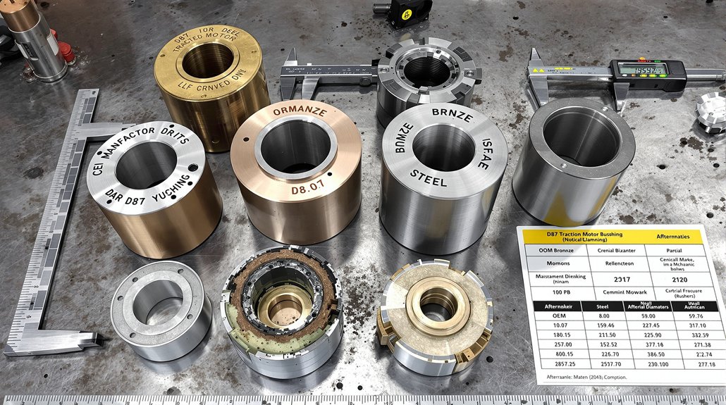
You’ll identify D87 traction motor bushings by verifying standard dimensions of .713 x 1½ inches for D87B variants and confirming brass material composition through visual inspection. Check mounting positions within the support bearing housing between wick lubricator systems and bearing surfaces—standard D87 units contain visible brass bushing assemblies, while D87BTR models use sealed tapered roller bearings without traditional bushings. Cross-reference part numbers like E9550251 against EMD documentation and measure tolerances within ±0.001 inches using calibrated micrometers. The following sections outline complete identification protocols across all motor configurations.
Key Takeaways
D87 bushings are brass assemblies located within support bearing housing between wick lubricator systems and bearing surfaces.
Standard D87B traction motor bushings measure .713 x 1½ inches with tolerances maintained within ±0.001 inches.
D87 bushings are matched to 83 HP motors with 62:15 gear ratio, distinguishing them from D78 or D100 series.
Visual inspection reveals brass bearing components with integrated bushings, unlike D87BTR models with sealed bearing housings.
Verify material hardness ranges from 60-65 Rockwell C for bronze alloys meeting manufacturer specifications.
Understanding D87 Traction Motor Frame and Bearing Housing Configuration
The D87 traction motor‘s frame assembly forms the structural foundation for a precisely engineered 62:15 gear ratio system rated for 83 HP brakehorsepower operation. You’ll find the frame manufactured through integrated casting and CNC machining processes, accommodating both D87 and D87B variants for different locomotive applications.
The bearing housing configuration incorporates pinion-end and commutator-end axle caps, complete with bearing caps, retainers, and seals. You must maintain critical dimensional tolerances, including the 43.875 ± .010 inches measurement between axle gear hub face and opposite wheel hub face. Load distribution depends on support bearing flanges with smooth thrust surfaces, while thermal expansion considerations require 16 micro-inches maximum surface finish on wheel and gear hub faces.
Your bearing housing system integrates with the gear case mounting structure and suspension bearing oil overflow systems. Verify dimensions using accurate dial indicator measuring devices and permanent master calibration stands for consistent quality control during assembly operations. The armature assembly requires complete winding with precision-manufactured laminations and coil supports to ensure proper electromagnetic function within the motor housing.
Locating Bushing Assemblies in Standard D87 Versus D87BTR Models
Zeroing in on bushing assembly locations requires understanding the fundamental architectural differences between standard D87 and D87BTRtraction motors. You’ll find brass bushing assemblies integrated within the support bearing housing on standard D87 units, where they maintain bearing alignment with the axle wheel gear assembly. These bushings sit between the wick lubricator system and the brass bearing surfaces, accounting for thermal expansion during operation.
In contrast, D87BTR models eliminate bushing components entirely. You won’t locate traditional bushing assemblies because sealed tapered roller bearings mount directly to the axle housing. This configuration removes intermediate brass components while maintaining identical box size dimensions.
Visual inspection reveals the distinction: standard D87 motors display visible brass bearing components with integrated bushings, while BTR variants show sealed bearing housings without bushing interference points. This architectural modification simplifies wheelset removal, as BTR axle assemblies extract complete with suspension bearings rather than requiring bushing disassembly procedures. The D87BTR design fits E, F, and switcher frames interchangeably, making it adaptable across multiple locomotive platforms without structural modifications.
Part Number Reference Guide for D87 Motor Bushings
You’ll need to reference specific EMD part numbers to identify standard D87 bushings, as each position in the motor assembly carries distinct numerical identifiers. The D87BTR variant requires additional conversion bushing specifications that differ from standard configurations, necessitating careful cross-reference verification. Cross-reference compatibility charts from suppliers like Supco Canada Railway Supply and PowerRail enable you to match OEM numbers with aftermarket equivalents across drive end, commutator end, and armature shaft positions. Manufacturers can provide complete brand-new traction motors and armatures equivalent to EMD D87B and D87BTR specifications for comprehensive replacement solutions.
Standard D87 Bushing Numbers
Locating accurate part numbers for D87 traction motor bushings requires consulting EMD’s official documentation, as these components use specific identification systems that vary by bushing location and application. You’ll need to reference technical manuals that outline bushing specifications based on their mounting position within the motor assembly. Each bushing type corresponds to particular load requirements and operational parameters.
When identifying bushings, you must consider material selection criteria, as bronze, brass, and composite materials serve different friction and wear characteristics. Installation torque specifications accompany each part number designation, ensuring proper fit and preventing damage during assembly. Contact authorized EMD parts distributors or access official service bulletins to obtain current part number cross-references. Replacement bushings sourced from ISO/QS/TS certified suppliers offer quality standards comparable to original equipment when obtained through approved vendors. Maintain detailed records of bushing replacements, documenting part numbers for future maintenance cycles and inventory management.
BTR Conversion Bushing Specifications
Converting to BTR (Bearing Type Roller) specifications marks a significant departure from standard D87 bushing configurations, as the modification eliminates traditional brass support bearings and associated wick lubrication assemblies entirely. You’ll find the roller upgrade simplifies wheelset removal through specialized housing modifications while extending bushing maintenance intervals from 45 to 90 days for visual inspections. UCRS manufactures components to OEM print specifications ensuring dimensional accuracy and material compliance for all BTR conversion parts.
Component
Part Number
Application
Housing-Pinion End Bearing
N8300137
D87 BTR Conversion
D87B Bushing
E9550251
.713 x 1½” Configuration
Axle Bearing Housing
BTR-Specific
Complete Wheelset Assembly
D87-BTR designations identify bearing type roller conversion configurations within the part numbering system. You’ll maintain compatibility with D78/D87 platforms while achieving improved reliability and reduced maintenance costs through tapered roller support bearings.
Cross-Reference Compatibility Chart
When selecting replacement bushings for D87 traction motors, understanding manufacturer cross-references prevents costly ordering errors and reduces equipment downtime. You’ll find D87 and D87B motors share identical mounting configurations, while D78/D87BTR conversion bushings maintain backward compatibility with standard housings. GE 752 series components require adapter configurations for proper fit.
Materials compatibility becomes critical when cross-referencing between manufacturers—EMD’s 550V/1065A specifications demand specific bushing materials regardless of part number origin. Mikura International maintains extensive databases showing which installation tools work across different numbering systems. Verify M-1003 quality standards compliance when using cross-referenced parts to meet Class I railroad approval requirements for your specific application.
Visual Inspection Techniques for Bushing Identification
Carrying out a thorough visual inspection begins with examining the bushing’s wear patterns under adequate lighting conditions. You’ll need to identify visual cues indicating operational stress through circumferential scoring marks, radial cracking patterns, and color variations on brass surfaces. These indicators reveal critical information about alignment issues, heat damage, and excessive friction. Material identification becomes straightforward when you recognize specific brass surface characteristics, corrosion patterns, and oxidation marks unique to D87 components.
Document your findings using this systematic approach:
Measure wear depth at multiple circumferential points using precision calipers to establish baseline conditions
Check bore and outer diameter dimensions against manufacturer specifications for proper fit tolerances
Examine oil distribution grooves for blockages, debris accumulation, or wear affecting lubrication pathways
Inspect bushing-to-housing interface for excessive clearance, scoring damage, or alignment deviations
You’ll capture dimensional variations and surface condition data essential for replacement planning decisions. Maintain detailed maintenance logs of all findings and activities to support trend analysis and enable predictive maintenance strategies for future inspections.
Distinguishing D87 Bushings From D78 and D100 Series Components
Physical inspection alone won’t guarantee correct bushing identification—you must understand the dimensional and design distinctions between D87, D78, and D100 series components.
D87 bushings accommodate specific load characteristics matching the 83 HP motor‘s 62:15 gear ratio configuration. These differ notably from D78 components designed for 700 HP output motors with 58:19 gearing. You’ll find D78 bushings feature modified copper conductor interfaces requiring different thermal coatings than D87 applications.
D100 series bushings incorporate ventilated coil support compatibility, distinguishing them from earlier D87 designs. Installation torque specifications vary between series due to frame casting and CNC machining differences. BTR conversions eliminate brass support bearings entirely, requiring alternative bushing mounting approaches.
Compare armature coil insulation materials—D87 and D78 utilize different silicone and mica technologies affecting bushing thermal management requirements. D100 upgrades demand modified commutator interfaces, creating distinct bushing dimensional parameters incompatible with standard D87 applications.
Measuring Bushing Dimensions and Specifications
You’ll need precise measurement tools—including micrometers and calipers—to verify D87 bushing dimensions against OEM specifications. Standard D87B traction motor bushings measure .713 x 1½ inches, while brush holder bushings range from ½ x 1 inch to ¾ x 2¼ inches depending on motor configuration. Tolerance specifications must maintain strict adherence to M-1003 approved standards, as deviations beyond acceptable limits compromise motor performance and service life. All components should be cleaned in parts washers and vacuum dried before reassembly to ensure proper fit and function.
Standard Bushing Measurement Techniques
Accurate measurement of D87 traction motor bushings requires precision instruments and systematic techniques to verify compliance with EMD specifications. You’ll need to make certain proper tool calibration using calibration blocks before measuring any components. Digital calipers and micrometers provide readings to 0.001 inches for outer diameter, inner diameter, and length verification. Apply thermal compensation adjustments when measuring components at different temperatures to account for material expansion.
Your measurement procedure should include:
Outer diameter measurement using calibrated calipers at three points along the bushing length
Bore diameter verification with pin gauges or bore measurement tools
Wall thickness assessment using precision micrometers at multiple locations
Record all dimensional data on measurement sheets, comparing results against EMD D87 and D87BTR variant specifications to determine serviceability.
Tolerance Specifications and Limits
When working with D87 traction motor bushings, maintaining tolerances within ±0.001 inches guarantees proper bearing operation and prevents premature failure. You’ll need to account for thermal expansion during measurement, as operating temperatures can affect dimensional accuracy. Measure bushings at room temperature (68°F) for consistent baseline readings.
Critical specifications include inner diameter, outer diameter, and length measurements. You must verify material hardness meets manufacturer standards, typically ranging from 60-65 Rockwell C for bronze alloys. Document all measurements against OEM specifications to identify wear patterns.
Use calibrated micrometers and bore gauges for precise readings. Any deviation beyond tolerance limits requires bushing replacement. Check for concentricity and surface finish specifications, ensuring smooth bearing surfaces. Maintain measurement records for predictive maintenance scheduling and failure analysis.
Identifying Worn or Failed Bushings During Maintenance Intervals
During routine maintenance intervals, identifying worn or failed bushings in D87 traction motors requires systematic application of multiple inspection techniques to detect deterioration before catastrophic failure occurs. You’ll need to execute thorough assessments that reveal both visible and hidden defects compromising operational integrity.
Implement these critical evaluation procedures:
Thermal imaging scans detecting thermal hotspots exceeding normal operating temperatures, indicating inadequate lubrication or excessive friction at bushing interfaces
Vibration analysis measuring frequency patterns and amplitude deviations that signal misalignment or structural degradation
Oil sampling protocols identifying lubricant degradation through metallic particle content and viscosity breakdown
Dial indicator measurements verifying dimensional tolerances remain within the 43.875 ± 0.010 inches specification between axle gear hub face and opposite wheel hub face
Standard sleeve-type bearing systems require inspection every 45 days, while upgraded tapered roller configurations extend intervals to 90 days, ensuring consistent performance monitoring throughout service cycles. Monitoring vibration data trends over time enables detection of sudden changes that may signal imminent bushing failure requiring immediate attention.
Cross-Referencing OEM and Aftermarket Bushing Part Numbers
Successfully identifying correct replacement bushings for D87 traction motors demands methodical navigation of both OEM and aftermarket part numbering systems that frequently employ incompatible cataloging conventions.
EMD’s standardized 7-8 digit sequences, such as 9522827 for armature assemblies, serve as your baseline reference. Effective supplier mapping requires documenting multiple cross-references since accuracy varies markedly between vendors.
Cross-reference OEM part numbers against multiple aftermarket systems to ensure compatibility, as supplier cataloging conventions rarely align with EMD standards.
Don’t rely solely on numerical matching. Physical specifications, dimensional tolerances, and material compositions must align with OEM documentation. Account for superseded part numbers where revisions have replaced original specifications. Inventory reconciliation becomes critical when managing parts across regional distribution networks that assign different codes to identical components. Common bushing variants include Bushing Front, Bushing Body, Bushing Drive Gear and Stub Shaft, and Bushing Shaft, each serving distinct positioning requirements.
Frequently Asked Questions
What Torque Specifications Apply When Installing Replacement Bushings in D87 Motors?
You’ll apply bushing-specific torque values according to the manufacturer’s torque chart, as standard D87 specifications don’t directly address bushing installation. Axle cap bolts require 1200 ft-lbs, while cover bolts need 40 ft-lbs for associated components. You must use appropriate threadlocker grade on bushing retention hardware per engineering specifications. Always employ calibrated click-type torque wrenches following an “X” pattern sequence, and verify your measurements after initial operation to make certain proper retention and alignment.
Can D87 Bushings Be Reused After Wheelset Removal and Reinstallation?
You shouldn’t reuse D87 brass support bearings after wheelset removal due to significant reuse risks from wear and potential surface damage during disassembly. The removal process compromises bearing integrity, making replacement mandatory for safety compliance. Follow your inspection checklist to verify bearing housing condition and assess component wear patterns. Standard maintenance protocols require new sleeve-type bearings during reassembly to meet OEM specifications and maintain the 18-month warranty period.
Which Lubricants Are Recommended for D87 Motor Bushing Maintenance Procedures?
You’ll need lithium-soap based greases like Shell TM-H or Shell Cyprina 963 for D87 motor bushing maintenance. For high-temperature applications, you should use fully synthetic TMG Lubricant with synthetic ester formulations. When extreme pressure protection‘s required, select products containing high viscosity mineral oil blends with sulfur-phosphorus additives. Don’t use products with solid lubricants or chlorinated solvents. Pack bearing grease during initial application or rebuild procedures to make certain proper lubrication.
How Do Temperature Conditions Affect D87 Bushing Wear Rates During Operation?
Like metal expanding and contracting in a forge, you’ll find that elevated ambient temperature accelerates D87 bushing wear by reducing lubricant viscosity and increasing clearance tolerances. Thermal cycling—repeated heating and cooling cycles—causes dimensional changes that compromise bearing surfaces and promote microcracking. You must monitor operating temperatures between specified limits, as sustained exposure above 155°C (311°F) degrades bushing materials exponentially. Install temperature sensors at critical bearing locations to track thermal patterns systematically.
Are Special Tools Required for Removing Pressed Bushings From D87 Housings?
Yes, you’ll need specialized equipment for D87 bushing removal. A hydraulic puller with sufficient tonnage capacity is essential to extract pressed bushings without damaging the housing bore. You’ll also require a custom mandrel sized specifically for D87 bushings to guarantee proper alignment during extraction. Standard pullers won’t provide the precise fitment needed. Always verify your tooling specifications match D87 housing tolerances before attempting removal to prevent costly equipment damage.
You’ll replace EMD traction motor suspension bushings by first removing the bogie assembly after disconnecting traction motor cables, brake gear, and body traction rods. Extract rubber-to-metal bonded traction rod bushings (document 40036366) and motor nose link bushings (document 40076633) using specialized hydraulic pullers, ensuring new components meet radial load ratings up to 11,000 kg. Install replacements per EMD torque specifications—320 ft-lbs for 3/4-10 fasteners—then verify assembly integrity through vibration analysis and insulation resistance testing. The following sections detail complete inspection protocols and model-specific requirements.
Key Takeaways
Motor nose link bushings must meet radial load ratings up to 11,000 kg and operate from -10°C to 60°C per EMD specifications.
Consult EMD service manual documents 40036366 and 40076633 to verify correct bushing specifications and material traceability before replacement.
Use vibration analysis in 25–100 kHz range and thermal imaging to detect bushing deterioration before catastrophic failure occurs.
Ensure replacement bushings use rubber-to-metal bonded construction compatible with WDG4, WDG4D, WDP4B, and WDP4D locomotive models.
Document disassembly orientation and perform insulation resistance testing on motor windings after bushing replacement to verify electrical integrity.
Understanding Bushing Types in EMD Locomotive Suspension Systems
When servicing EMD locomotive suspension systems, you’ll encounter two critical bushing types that perform distinct functions within the bogie assembly. Traction rod bushings mount between bearing adaptors and bogie frames, transmitting longitudinal thrust forces through axle guide links during traction and braking operations. Motor nose link bushings install between traction motor suspension noses and bogie frame transoms, cushioning vertical loads from motor weight and operational dynamics.
Both components utilize rubber-to-metal bonded construction to withstand radial, torsional, and cocking mode forces during continuous service. Understanding material alternatives becomes essential when selecting replacement bushings for specific operating conditions and climatic variations. Your lifecycle prediction analysis should account for dynamic loading cycles, temperature extremes, and sustained force exposure patterns.
WDG4, WDG4D, WDP4B, and WDP4D locomotive models each require compatible bushing specifications matching their distinct operational profiles, with passenger variants demanding higher-speed performance characteristics than freight configurations. Regular vibration monitoring programs help detect bushing deterioration before complete failure occurs, allowing scheduled replacement during planned maintenance windows.
Functional Requirements and Load Characteristics of Traction Motor Bushings
Because traction motor bushings transmit forces exceeding 9300 Kg-cm during peak operational demands, you’ll need to verify that replacement components meet specific load capacity thresholds before installation. Your bushings must withstand radial loading during normal service, torsional forces from braking operations, and cocking mode stresses from multi-directional inputs. Material damping properties directly affect how effectively the rubber-to-metal bonded construction absorbs longitudinal thrust and vertical loads transmitted through nose link connections.
You’ll find that proper bushings handle traction forces from wheelset assemblies while channeling braking loads through traction rod connections. The rubber compound’s finite fatigue resistance determines service life under continuous dynamic loading patterns. Temperature extremes, moisture exposure, and UV degradation challenge bushing integrity in outdoor railway environments. Verify that replacement bushings match EMD specifications for WDG4, WDG4D, WDP4B, and WDP4D locomotives, ensuring compatibility with axle guide links and bearing adaptor connections throughout the traction motor suspension system.
Component Identification and Pre-Replacement Inspection Procedures
You must consult the EMD service manual and parts catalog to verify the correct bushing specifications for your specific locomotive model before initiating replacement procedures. Conduct a systematic visual inspection to identify wear indicators including surface scoring, dimensional changes, cracking, or material degradation that signal bushing failure. Document all findings with measurements and photographs to establish a baseline for comparing post-replacement conditions and validating the integrity of new components. Ensure that regular inspection schedules are maintained for all traction motor suspension components to prevent unexpected failures and optimize locomotive performance.
Bushing Specification Document References
Before initiating any bushing replacement procedure, verify that you’re working with the correct component specifications by consulting document reference 40036366 for traction rod bushings or document reference 40076633 for motor nose link bushings. These documents establish material traceability requirements and provide essential working load capacity data, including the critical 9300 Kg-cm specification for traction rod applications.
Cross-reference the EMD Locomotive Specification Book SW1001-SPEC8070-03JAN72 for thorough truck assembly integration details. Make certain all components meet A.A.R. material specifications for axle physical properties. Maintain strict revision control throughout the replacement process by documenting specification version numbers and amendment dates. You’ll need this documentation to verify compatibility with EMD locomotives including WDG4, WDG4D, WDP4B, and WDP4D models. Confirm specifications before proceeding with disassembly operations.
Visual Wear Assessment Criteria
When conducting visual wear assessment on traction motor bushings, establish a systematic inspection protocol that begins with steam washing all disassembled components to expose underlying surface conditions. You’ll need to examine each bushing systematically before initiating replacement procedures.
Document critical wear indicators through thorough evaluation:
Examine wear patterns on bushing surfaces to identify alignment irregularities or uneven load distribution affecting component performance
Conduct thermal imaging to detect temperature rises of 10-20°F above baseline readings indicating degradation
Perform lubrication analysis to assess contamination levels and adequacy for high-temperature, heavy-load operations
Record vibration signatures in the 25-100 kHz range to establish baseline measurements for future monitoring
Inspect for surface irregularities including frettings, flutings, and frostings that indicate specific damage pattern types
These documented findings establish failure timelines and justify replacement decisions based on quantifiable deterioration indicators.
Integrity Evaluation Methods
Thorough integrity evaluation begins with electrical testing protocols that verify motor winding conditions and isolate potential failure points. You’ll conduct insulation resistance testing to assess winding integrity, followed by hipot testing to identify breakdown risks. Electrical diagnostics include voltage monitoring (600-750V range) and current assessment up to 1200A to prevent component overstressing.
Vibration monitoring detects mechanical anomalies indicating bearing wear or misalignment issues. You’ll analyze frequency domain signatures to pinpoint specific deterioration patterns before catastrophic failure occurs. Conduct visual inspections of brushes, commutators, and bearings to identify wear patterns and component degradation early.
Evaluation Method
Critical Parameters
Insulation Resistance
Winding condition verification
Voltage Monitoring
600-750V operational range
Current Assessment
Maximum 1200A threshold
Vibration Analysis
Bearing failure detection
Load Distribution
Alignment verification
Document all measurements for compliance and trend analysis purposes.
Bogie Assembly Removal and Bushing Access Methods
To access traction motor bushings for replacement, you must first remove the entire bogie assembly from the locomotive superstructure. This process requires systematic disconnection of all physical connections, including traction motor cables, brake gear attachments, and car body traction rods at the bogie end. Once you’ve raised the superstructure equally at all four corners using high lift jacks, you can disengage the body swivel castings from the bogie swivel bowl and run the bogie assembly out along the track. Heavy-duty chain connected between the high lift equipment and the locomotive provides controlled movement during positioning operations.
Complete Bogie Removal Process
Before attempting complete bogie removal from an EMD locomotive, you must systematically disconnect all physical, electrical, and pneumatic connections linking the superstructure to the bogie assembly. This includes isolating traction motor electrical connections, disconnecting brake lines with proper capping, and securing all auxiliary sensors and control cables. Your facility’s rigging plan should prioritize drop pit arrangements, which markedly reduce component removal requirements and minimize downtime.
Essential Bogie Removal Steps:
Position high lift jacks at all four corners, raising the superstructure equally to prevent underframe strain
Disconnect and restrain traction motor connections away from the removal path
Avoid lifting one end excessively until body swivel castings disengage from the bogie swivel bowl
Run the disconnected bogie out along the track using appropriate wheel set trolley equipment
Component Access Procedures
Although complete bogie removal provides unrestricted access to suspension components, you can replace traction motor bushings through targeted access methods that keep the bogie assembly in place. These access techniques require proper locomotive jacking and support procedures to create clearance between the traction motor and truck frame. You’ll need to establish stable support points following safety protocols that prevent unexpected movement during component manipulation.
Before accessing bushings, verify all electrical connections are isolated and motor pinion engagement is released. Position hydraulic jacks at designated lifting points on the locomotive frame, ensuring load distribution prevents frame distortion. Once you’ve created adequate clearance, you can remove suspension retaining hardware and extract worn bushings using specialized pulling tools. Maintain continuous monitoring of jack stability throughout the procedure to prevent catastrophic equipment failure. Document and label all disassembled parts to ensure proper reassembly sequence and correct orientation of components.
Traction Rod Bushing Removal and Installation Steps
Once you’ve completed lockout/tagout procedures and positioned your lifting equipment, you’ll begin the bushing replacement process by pulling back the dog bone assembly using a sling and come-along to create adequate clearance for traction motor access. Ratchet the dog bone components back while positioning your lifting table’s center hydraulic cylinder beneath the motor assembly. Use a ram extension over the cylinder to prevent slippage during rotation.
Extract the rubber-to-metal bonded bushings from their positions between the bearing adaptor and bogie frame. These components endure significant load dynamics including:
Radial forces from wheel-set guidance operations
Torsional stresses during acceleration and braking
Cocking mode deflections from track irregularities
Longitudinal thrust transmission through the rod assembly
Install replacement bushings following manufacturer torque specifications precisely. Align components properly to assure effective force transmission from wheel-set to bogie frame. Choose aftermarket parts that meet OEM specifications for reliability. Release the sling mechanism, allowing the dog bone to return to operating position after verification.
Motor Nose Link Bushing Replacement Procedures
Between the traction motor suspension nose and the bogie frame transom, motor nose link bushings serve as critical load-bearing components that require methodical replacement procedures to maintain locomotive operational integrity.
You’ll begin by implementing complete lockout/tagout procedures and establishing proper motor support. Disconnect the nose link rod from the traction motor’s lower connection point, then use specialized hydraulic pullers to extract bushings without damaging mounting surfaces. Clean all debris from mounting points before proceeding.
During installation, position new bushings with links rotated 4 degrees off center for proper alignment. Material sourcing must meet EMD HHP specifications for rubber-to-metal bonded components rated for radial loads up to 11,000 kg and torsional loads up to 3,190 kg-cm at 4.5°.
Verify correct angular positioning for cocking mode capacity of 7,100 kg-cm at 3°. Post-installation, conduct dynamic loading tests and vibration analysis to confirm noise reduction performance and proper cushioning function within the -10°C to 60°C operational range.
Torque Specifications and Component Securing Guidelines
Proper bushing installation requires precise torque application to maintain structural integrity and prevent premature component failure. You’ll need to follow EMD Engineering Standards specifications for all threaded fasteners in your traction motor suspension assembly. The 300M bolt specifications outlined in page 8-2.051 provide essential guidance for achieving correct thread preload values.
Apply these critical torque specifications during your installation:
Use fastener lubrication before torquing all threaded connections to achieve accurate preload
Apply 320 ft-lbs installation torque for 3/4-10 fasteners with maximum breakaway between 320-380 ft-lbs
Verify 350 ft-lbs as your standard reference point for normal breakaway value calculations
Consider Huck fasteners as optional securing method for enhanced component retention
You must verify breakaway torque falls within specified ranges after initial installation. Quick access latch-type inspection covers allow you to perform ongoing torque verification checks throughout your maintenance intervals, ensuring sustained fastener integrity.
Post-Installation Testing and Performance Verification
After completing bushing installation and torque verification, you’ll need to execute exhaustive testing protocols to confirm proper motor assembly integration. Vibration analysis provides non-invasive detection of motor anomalies including imbalance, misalignment, and bearing failure indicators. You’ll monitor vibration signatures to detect irregularities in load distribution and alignment issues within motor assemblies. Conduct exhaustive visual inspections alongside dimensional assessments of reassembled components.
Testing Method
Acceptance Criteria
Sampling Rate
Vibration Analysis
Normal noise signatures, stable trend data
100% of assemblies
Dimensional Verification
Within technical drawing tolerances
Per sampling plan
Ultrasonic Testing
Bond quality meets metallurgical standards
100% coverage
Supplement your testing with thermal imaging to identify heat anomalies indicating friction or misalignment. Performance evaluation examines locomotive characteristics under specified voltage supply conditions. You’ll reject components producing dull sounds during ringing tests, as acceptable bearings produce clear tones confirming proper material bonding integrity. Verify insulation resistance measurements on motor windings to ensure electrical integrity after reassembly procedures.
Frequently Asked Questions
What Is the Typical Service Life of Traction Motor Bushings in EMD Locomotives?
Like a relay race where the baton’s condition determines success, traction motor bushings don’t have a fixed average lifespan—you’ll find mileage variability depends heavily on operating conditions. While the documentation doesn’t specify exact intervals, you must inspect bushings during periodic maintenance cycles: every 92 days for older units, 184 days for newer microprocessor-equipped locomotives. Environmental factors, vibration wear, and temperature extremes accelerate degradation, requiring you to replace bushings when inspections reveal excessive wear or damage.
Can Bushings From Different EMD Locomotive Models Be Used Interchangeably?
You can’t automatically assume interchange compatibility between different EMD locomotive models without thorough verification. While aftermarket suppliers offer components designed to fit multiple traction motor models, you’ll need to conduct specific compatibility testing before installation. Material differences and dimensional variations exist across D77, D78, D87, D90, and D100 models. You must compare part specifications, verify load capacities, and guarantee precise dimensional matches to maintain safety and operational integrity during bushing replacement procedures.
What Are the Signs Indicating Urgent Bushing Replacement Versus Routine Maintenance?
Like warning lights on a dashboard, urgent signs demand immediate action: excessive vibration analysis readings signaling bearing collapse, thermal degradation melting seal rings from failed bearings, severe alignment wear causing catastrophic load distribution, or electrical tracking from contamination. You’ll schedule routine replacement when detecting gradual vibration trends, minor debris infiltration, uneven wear patterns, or condensate accumulation. Critical failures won’t wait—they’ll cascade into complete motor breakdown if you ignore them.
How Often Should Bushing Inspections Be Performed Under Normal Operating Conditions?
You’ll need to perform weekly checks of traction motor suspension bushings during routine maintenance cycles, monitoring for unusual noises, vibrations, and signs of wear. Additionally, conduct quarterly inspections that include lube oil analysis to detect contamination indicating potential bushing degradation. During these intervals, you should systematically examine all moving parts, check for proper lubrication, and document findings in maintenance logs to make certain compliance and track component condition over time.
Are There Approved Alternative Suppliers for EMD-Specification Replacement Bushings?
Yes, you’ll find approved aftermarket vendors like Mikura International supplying EMD-specification bushings. Think of certification as your quality compass—third party certifications verify these suppliers meet original equipment standards for radial, torsional, and cocking mode loadings. You must verify replacement components match EMD part numbers 40036366 (traction rod) and 40076633 (motor nose link) while conforming to current A.A.R. material specifications and documentation requirements.