
You’ll maintain EMD locomotive gear drives through daily pre-operation inspections of housing integrity, drive assemblies, and seal conditions, plus mandatory 184-day thorough examinations. Monitor oil pressure ranges of 8-12 psi at idle and 25-29 psi at full speed using proper lubrication schedules. Replace turbocharger oil filters every 1,400 hours and perform monthly cleaning of lube oil strainers. Check component alignment, bearing preload specifications, and temperature differentials regularly. These systematic protocols will reveal advanced troubleshooting techniques and emergency response procedures.
Key Takeaways
- Conduct daily visual inspections of gear drive assemblies for wear patterns, scoring, or metal fatigue signs.
- Perform systematic gear drive examinations every 184 days, listening for unusual noises and monitoring vibrations.
- Maintain proper lubrication by checking oil levels and quality per manufacturer specifications during inspections.
- Monitor temperature differentials between gear drive components to identify potential performance issues early.
- Document all gear drive maintenance findings in logs to ensure regulatory compliance and guide future maintenance.
Daily Pre-Operation Inspection Protocols for Gear Housing Systems
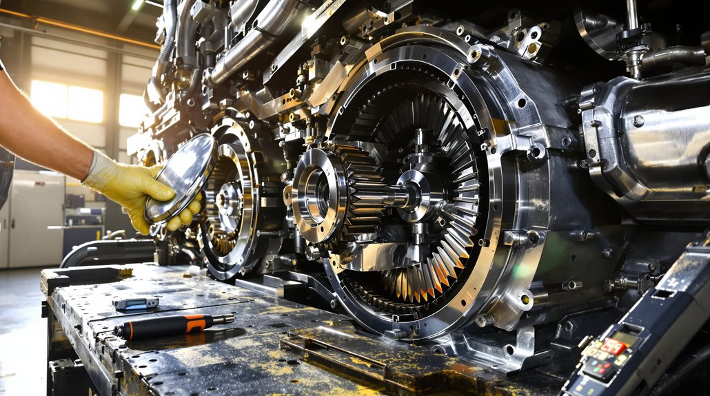
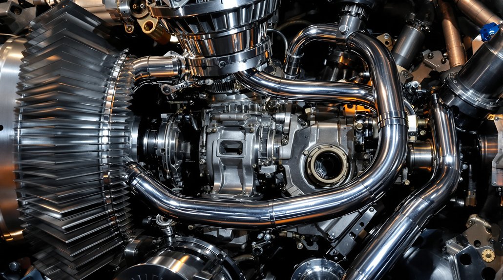
Starting off your daily routine with a systematic gear housing inspection sets the foundation for reliable locomotive operations and prevents costly mechanical failures. Begin with a thorough visual inspection of the exterior housing, checking for cracks, structural damage, and mounting bolt integrity. Examine drive gear assemblies for wear patterns, scoring, or metal fatigue that could indicate impending failure.
Conduct thorough seal testing around gasket interfaces and connection points, monitoring for oil leaks or fluid accumulation beneath assemblies. Check drain plugs, fill ports, and cooling line connections for proper sealing specifications. Verify mechanical clearances between rotating components and housing walls, ensuring proper alignment of drive assemblies within operational parameters. Inspect locomotive trucks, wheels, gear cases, and drive gears for cracks or physical defects, as these components experience significant stress during brake shoe operations and require careful monitoring for structural integrity.
Don’t overlook safety equipment verification—confirm protective guards are secure, walkways are clear, and emergency shutdown systems function properly. Document all findings in standardized maintenance records, noting deviations from normal parameters and any required corrective actions for regulatory compliance.
Lubrication System Management and Filter Maintenance Schedules
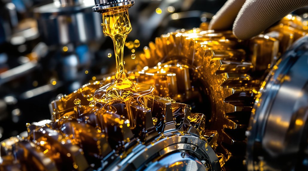
You’ll need to establish a systematic approach to lubrication system management that coordinates filter replacement intervals with oil pressure monitoring requirements. Your maintenance schedule must align filter changes at 1400-hour intervals with thorough crankcase system inspections to prevent contamination buildup and guarantee peak gear drive performance. Monitor oil pressure control valve operation during each service cycle, as inadequate pressure at idling speeds below 200 RPM can compromise bearing lubrication in drilled rod systems. Document all maintenance activities in a comprehensive maintenance log to ensure compliance with manufacturer specifications and establish a reliable service history for future troubleshooting needs.
Filter Replacement Intervals
Proper filter replacement intervals directly impact your EMD locomotive’s operational reliability and component longevity. You’ll need differential monitoring systems installed to qualify for extended two-year intervals on main, auxiliary turbocharger, and fuel filters. Without this monitoring, you must maintain annual replacement schedules to prevent system failures.
Critical Filter Replacement Schedule:
- Turbocharger oil filters – Replace every 1,400 hours using original equipment specifications to protect high-speed bearings
- Engine-mounted fuel filters – Monthly replacement with elements meeting original equipment standards
- Rack-mounted fuel filters – Monthly changes using pleated cotton-paper elements only
- Lube oil strainers – Clean monthly with mandatory oil refill before operation
You can extend intervals by 25% when technical specifications permit, but always prioritize original equipment filter specifications for peak filtration effectiveness. Following manufacturer guidelines prevents emergency repairs, which cost 3-4.7 times more than scheduled maintenance and helps maintain continuous operational efficiency.
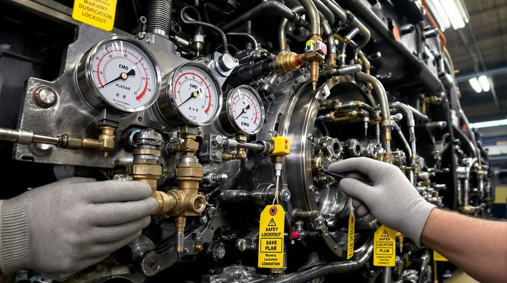
Oil Pressure Monitoring
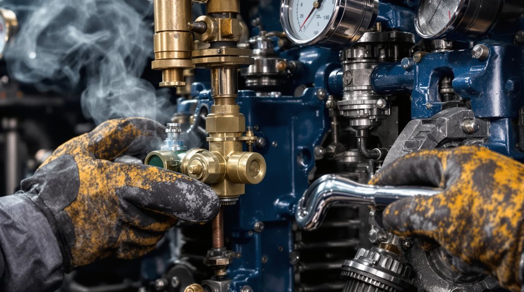
Continuous oil pressure monitoring serves as your locomotive’s primary defense against catastrophic engine failure, requiring vigilant attention to operating parameters that range from 8-12 psi during idle to 25-29 psi at full speed. EMDEC sensors detect pressure directly at manifold passages, ensuring optimal placement for accurate readings throughout the lubrication system.
Your governor-integrated shutdown systems establish critical alarm thresholds with 1-2 second delay periods, preventing false shutdowns while protecting bearings. When pressure drops below minimum thresholds, automatic protection systems engage immediately. You’ll notice the governor’s push button extending 3/8 inch with visible red warning bands when safety systems activate.
Monitor your gear-type oil pumps working with crankcase-mounted pressure control valves to maintain adequate pressure across all operating speeds, ensuring proper lubrication reaches crankshaft passages and turbocharger systems. Filter elements should be changed when pressure exceeds 25 PSI at rated RPM to prevent bypass conditions and maintain optimal oil flow.
Crankcase System Maintenance
Effective pressure monitoring systems depend on clean oil circulating through properly maintained crankcase components, making systematic lubrication system management your next priority for locomotive reliability. Your maintenance approach must integrate crankcase ventilation system care with thorough filter replacement schedules to prevent catastrophic engine failure.
Execute these critical maintenance procedures during scheduled intervals:
- Complete oil drainage – Remove bottom pipe plug and drain cooling water simultaneously before disassembly operations
- Solvent flushing – Clean crankcase interior with petroleum solvent, then wipe with lint-free towels
- Filter system service – Replace air filters, breather components, and inspect pressure relief valve operation
- Component inspection – Perform magnetic-particle testing on cleaned parts, avoiding wire brushing on pistons and crankshafts
Schedule thorough crankcase maintenance during major overhaul cycles based on operating hours rather than calendar time.
Traction Motor Gearing Component Service Procedures
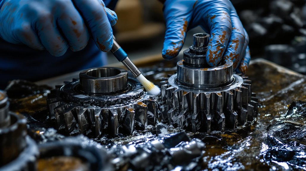
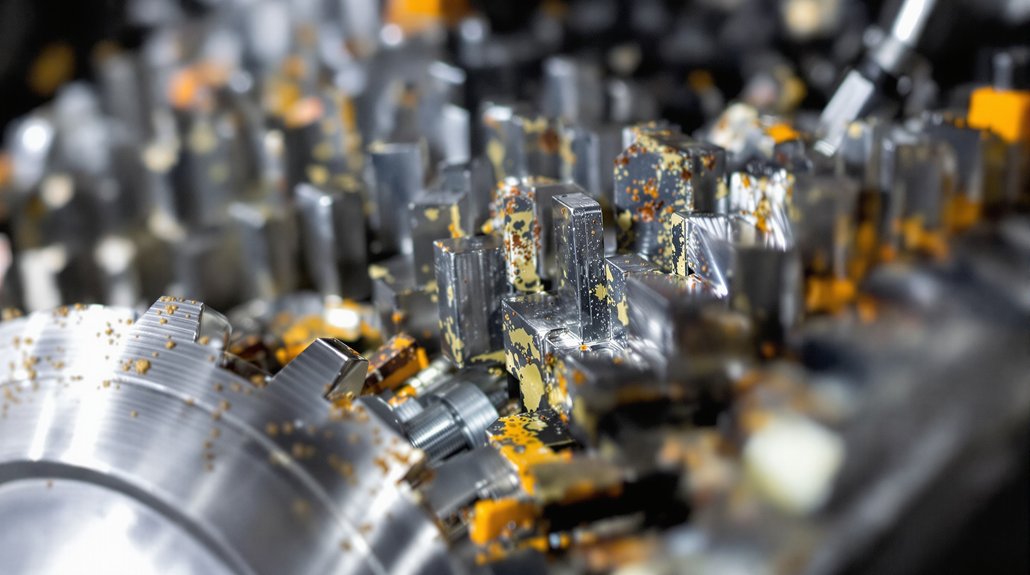
Breaking down traction motor gearing component service requires systematic attention to inspection, lubrication, alignment, and preventive maintenance protocols. You’ll need to examine pinion and gear components closely, detecting abnormal wear patterns that indicate replacement needs. Conduct thorough visual inspections of gear teeth for pitting, cracking, or excessive wear while performing noise diagnosis to identify misalignment issues.
During disassembly procedures, check bearing preload specifications and verify shaft balancing meets manufacturer standards. Use high-grade lubricants specifically designed for high-load gear systems, applying proper gear oil for newer traction motor combinations. Monitor temperature conditions regularly as part of your all-encompassing protection strategy.
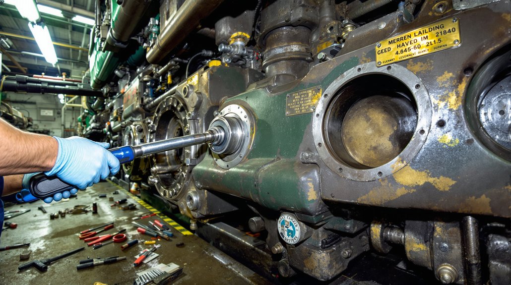
Follow precise alignment procedures using calibrated torque wrenches, adhering meticulously to manufacturer specifications. Re-check torque values after initial operation periods to confirm proper tightening. Implement 184-day inspection schedules for locomotives with microprocessor controls, conducting steam washing procedures and exhaustive testing to identify problems before component failure occurs. Utilize vibration monitoring systems to detect bearing irregularities and gear mesh problems that may not be visible during standard inspections.
Troubleshooting Low Oil Pressure and Safety System Responses
When your EMD locomotive’s oil pressure drops below safe operating levels, you’ll need to quickly identify the cause and respond to automatic safety system activations. The engine’s governor safety controls will immediately shut down operations once low pressure conditions are detected, requiring you to understand both the diagnostic process and proper reset procedures. Your ability to troubleshoot pressure loss sources and safely restart the system after emergency shutdowns directly impacts both locomotive availability and operational safety. Start by checking the crankcase oil level as insufficient oil below the pump supply tube will prevent proper circulation to critical engine components.
Low Pressure Detection
Although EMD locomotives incorporate multiple pressure monitoring systems, you’ll need to understand how these interconnected detection points work together to prevent catastrophic engine damage. Your governor safety controls continuously monitor lubricating oil pressure at 70 PSI during normal operation, triggering immediate shutdown when levels drop dangerously low. Detection occurs on both the pump’s suction side and within the main circulation system.
Critical monitoring includes:
- Filter pot pressure monitoring – provides independent detection separate from main engine readings
- Electronic sensor calibration – guarantees accurate pressure readings and electrical signal generation
- Visual and audible alarm testing – verifies yellow signal lights and alarm bells function properly
- Automatic filter bypass activation – engages when pressure differential exceeds 40 PSI across elements
Regular alarm testing prevents detection failures. Engine temperatures cause oil to thin and reduce pressure readings throughout the monitoring system.
Governor Safety Controls
Your locomotive’s governor safety controls act as the final barrier between low oil pressure detection and catastrophic engine failure. When the Woodward Governor‘s electro-hydraulic system detects low oil pressure or high vacuum on the lube oil pump’s suction side, it initiates redundant shutdowns through multiple safety mechanisms.
The governor’s push button extends 3/8″ and exposes a red band, while yellow “LOW OIL” and purple “NP” lights activate immediately. Electrical interlocks prevent restart until you press the reset button and move the isolation switch to “START” position. These dual reset actions stop alarm bells and extinguish alternator failure lights. You’ll find the control unit in your cab with the actuator mounted directly on the engine for immediate response. Regular troubleshooting of governor components helps identify potential issues before they trigger emergency shutdowns.
Emergency Shutdown Procedures
Should your locomotive experience an emergency shutdown, you’ll need to quickly assess whether the cause stems from low oil pressure or another safety system response. Emergency shutdowns bypass normal procedures and require systematic troubleshooting to prevent recurring failures.
Emergency Shutdown Response Protocol:
- Check alarm indicators – Yellow “Low Oil” lights and blue “Alternator Failure” signals indicate specific system failures requiring immediate attention
- Locate governor reset button – Look for the 3/8 inch extension with red band exposure indicating safety shutdown activation
- Complete reset sequence – Press governor reset button fully, then move isolation switch to “START” position to extinguish alarms
- Document incident details – Record shutdown cause, alarm patterns, and reset procedures for crew training and maintenance analysis
Wait forty seconds before restart attempts to allow system stabilization and cause determination.
Turbocharger Integration With Gear Drive Cooling Systems
Through careful integration of turbocharger and gear drive cooling systems, you’ll achieve peak thermal management that protects both critical engine components from heat-related failures. Proper aftercooler integration requires finned-tube designs that maximize surface area between compressed air and your cooling system. You’ll need copper and aluminum materials for optimal thermal conductivity in tubes and fins.
Configure multiple-pass systems so compressed air flows through the aftercooler several times, enhancing cooling efficiency. Install air-side and water-side separators to prevent moisture accumulation that damages turbocharger components.
Focus on coolant routing through gear-driven pumps that maintain consistent flow throughout the system. These positive displacement pumps handle high flow rates essential for turbocharger cooling under demanding conditions. You’ll want dual gear pump configurations to enhance pressure and flow capacity.
Maintain pressurized cooling systems for consistent circulation through both turbocharger and gear drive components, ensuring thorough thermal protection. Monitor heat transfer rate and airflow speed regularly to enable early detection of system problems before they affect locomotive performance.
Performance Monitoring Through Dynamic Brake Operations
When dynamic brake operations place extreme thermal and electrical loads on your locomotive’s gear drive system, thorough performance monitoring becomes essential for preventing catastrophic failures and optimizing braking efficiency. Real time diagnostics enable continuous assessment of critical parameters during high-stress braking cycles.
Real-time monitoring prevents catastrophic gear drive failures during high-stress dynamic braking operations through continuous assessment of critical locomotive parameters.
Your monitoring strategy should focus on these key areas:
- Traction Motor Current Analysis – Monitor individual motor currents through 4-20 ma sensor inputs to detect imbalances that stress gear components during dynamic braking
- Temperature Management – Track thermal conditions across gear housings using integrated sensor networks to prevent overheating damage
- Axle Specific Monitoring – Implement Individual Axle Control technology with dedicated inverters to assess rear axle loading more intensively than front axles
- Voltage Monitoring – Utilize analog inputs with 0.1V resolution across 0-80V ranges for precise electrical parameter tracking during brake engagement
Dynamic braking adjustments during these monitoring cycles help manage speed variations and enhance overall traction control under changing operational conditions.
Machine learning algorithms analyze historical performance data, enabling predictive maintenance scheduling that reduces operating costs while maximizing gear drive reliability.
700-Hour and 1400-Hour Maintenance Interval Requirements
Thorough gear drive maintenance extends beyond real-time monitoring into structured interval-based procedures that form the backbone of reliable locomotive operations. You’ll need to establish a disciplined inspection cadence that aligns with EMD’s proven maintenance intervals for optimal gear drive performance.
At regular inspection intervals, you must systematically examine gear drives for wear patterns, unusual noises, and vibrations that indicate potential failures. Your maintenance schedule should incorporate lubrication checks, guaranteeing proper oil levels and quality meet manufacturer specifications. Temperature differential monitoring between components provides critical performance data you can’t afford to overlook.
Component alignment verification becomes essential during these intervals, as misalignment causes accelerated wear and catastrophic failures. You’ll want to inspect drive system mechanical integrity, checking for loose bolts, damaged seals, and abnormal clearances. Document all findings meticulously, as these records guide future maintenance decisions and safeguard regulatory compliance while maximizing gear drive reliability.
Emergency Shutdown Procedures and Governor Control Systems
Although normal locomotive operations rely on predictable maintenance schedules, emergency situations demand immediate response protocols that can mean the difference between minor incidents and catastrophic failures. Your locomotive’s governor safety control mechanisms serve as the primary line of defense against engine damage during critical system failures.
Governor safety controls stand as your critical defense against catastrophic engine failures when emergency situations override standard maintenance protocols.
Emergency Response Protocol
- Governor Reset Verification – Check if the reset button extends 3/8 inch with red warning band exposed, indicating automatic shutdown activation
- Diagnostic Logging Window – Utilize the 40-second delay after restart to identify and document shutdown causes before normal operations resume
- Operator Ergonomics Assessment – Access emergency stop button on throttle handle for immediate shutdown without triggering governor systems
- Integrated Protection Response – Monitor yellow “Low Oil” and blue “Alternator Failure” signal lights while coordinating alarm bell shutoff through both governor reset and isolation switch repositioning
Understanding these emergency procedures guarantees you’ll respond effectively when protective systems activate during low oil pressure or water pump differential failures.
Frequently Asked Questions
What Gear Drive Components Require Replacement During Major Locomotive Overhauls?
You’ll replace 58 tooth gear assemblies and 19 tooth gears during major overhauls due to high stress loads. Inspect bearing assemblies for wear patterns and replace damaged components. Check tooth profiling on 22 tooth and 57 tooth gears for surface degradation. Replace armature assemblies and rewind kits completely. Don’t overlook pinion gear alignment specifications and bull gear surface hardening treatments for safety compliance.
How Do Environmental Conditions Affect Gear Housing Seal Longevity and Replacement Intervals?
Environmental conditions markedly accelerate seal degradation, requiring you to adjust replacement intervals based on climate impact. Extreme temperature fluctuations cause TPU seals to crack and lose flexibility, while chemical exposure from diesel fuel and ozone creates material breakdown. You’ll need shorter inspection cycles in harsh climates, monitoring for surface damage and proper seating to prevent pressurized oil leakage during operation.
What Torque Specifications Apply When Reassembling Gear Drive Housing Bolts and Fasteners?
You’ll apply specific torque values ranging from 90-335 ft-lbs depending on fastener size and application—gear box mounting bolts requiring the highest at 335 ft-lbs. Use proper torque calibration equipment to guarantee accuracy within ±3% tolerance. Maintain fastener traceability records for safety compliance. Follow sequential tightening patterns on housing joints, verify thread condition before assembly, and lubricate threads to prevent galling during installation procedures.
Can Gear Drive Oil Be Mixed Between Different EMD Locomotive Models?
Yes, you can mix gear drive oil between different EMD locomotive models due to standardized specifications. EMD’s oil compatibility guarantees lubricant mixing across 645 and 710 engines without performance issues. You’ll maintain consistent viscosity grades and base number requirements when mixing oils between models. However, you must verify both oils meet zinc-free and chlorine-free formulation requirements for proper component compatibility and operational safety.
What Warranty Coverage Exists for Gear Drive Failures in Rebuilt Locomotives?
EMD provides limited warranty coverage for gear drive failures in rebuilt locomotives, but you’ll face significant warranty exclusions if you’ve used non-authorized lubricants or components. Coverage typically doesn’t transfer between owners, creating transferability limits that affect resale value. You must maintain documented service intervals and use only EMD-approved parts to preserve protection. Third-party modifications void coverage entirely, leaving you responsible for costly gear drive repairs and potential cascading transmission failures.
You may also like to read: Service Manual EMD