
This comprehensive report examines the critical role of EMD parts 10634215 and 10634216 within the EMD 710 series locomotive engine system, specifically their function as hardware mounting components for dynamic brake resistor grids. These seemingly small part numbers represent essential infrastructure components that enable one of the most sophisticated electrical braking systems in modern railroad operations. The EMD 710 engine, which succeeded the earlier 645 series in 1985, represents a significant technological advancement in locomotive propulsion, incorporating turbocharged operation exclusively and electronically controlled unit injectors.
Within this advanced engine architecture, parts 10634215 and 10634216 serve as precision mounting hardware that maintains proper alignment and spacing of dynamic brake resistor elements, directly contributing to safe locomotive operation on grades and during emergency braking scenarios. Understanding these components requires examination of their specific design characteristics, their integration within the broader dynamic braking system, the EMD 710 engine platform itself, maintenance protocols, and comparative analysis with alternative systems used in competing locomotive platforms.
Understanding the EMD 710 Engine Architecture and Design Philosophy
The Evolution from EMD 645 to EMD 710
The EMD 710 represents a deliberate engineering evolution rather than a radical redesign of locomotive diesel propulsion technology. When the 645F series proved unreliable in early 1980s 50-series locomotives, EMD recognized the need for enhanced performance characteristics while maintaining compatibility with existing locomotive frames and mounting systems. The primary distinction between the 645 and 710 lies in stroke length, with the 710 incorporating a 1-inch (25 millimeter) longer stroke (11 inches or 279 millimeters) compared to the 645’s 10-inch (254-millimeter) stroke.
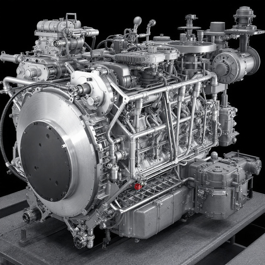
This design change, combined with the cylinder bore dimensions of 9 3/16 inches, produces the characteristic 710 cubic inches (11.6 liters) of displacement per cylinder that gives the engine family its designation. The engineering philosophy underlying this approach demonstrates how designers could achieve greater power output without substantially increasing external dimensions or weight, thereby gaining significant improvements in horsepower per unit volume and horsepower per unit weight relative to the earlier engine generation.
The EMD 710 engine architecture maintains the fundamental two-stroke, 45-degree V-configuration that characterized its predecessors. This configuration provides inherent balance characteristics and mechanical symmetry that simplify manufacturing while maintaining reliability during extended service life. The uniflow scavenging methodology with four poppet exhaust valves in the cylinder head represents the sophisticated gas exchange system required for two-stroke operation.
Two-stroke diesel engines compress air to extremely high pressures, then inject fuel directly into the combustion chamber, relying on spontaneous ignition rather than spark plugs as required in gasoline-fueled engines. The compression ratio of the EMD 710 operates at approximately 16 to 1, which falls within the typical diesel engine range of 14 to 1 up to as high as 25 to 1, enabling the superior fuel efficiency that characterizes diesel propulsion compared to alternative engine technologies.
Turbocharging as a Standard Feature
A fundamental distinguishing characteristic of the EMD 710 from both the 567 and 645 engine families concerns turbocharging requirements. While earlier generations could utilize either Roots blowers or turbochargers, the 710 engine is only offered with turbocharging, reflecting EMD’s commitment to maximizing efficiency and power output. This standardization represents a critical design decision that impacts every aspect of the engine’s thermal management, air intake, and exhaust systems. The turbocharger employed in the EMD 710 incorporates a gear-driven design that includes an overrunning clutch, allowing it to function as a centrifugal blower at low engine speeds when exhaust gas flow and temperature prove insufficient to drive the turbine independently.
The sophisticated turbocharger system operates through a well-coordinated sequence of mechanical and pneumatic functions. During engine starting, low-speed operation, and rapid acceleration phases, insufficient exhaust heat energy reaches the turbine to drive it at required speeds, necessitating mechanical assist through the gear train system connected to the engine’s crankshaft. This mechanical assistance occurs through a planetary gear drive system that channels energy from the crankshaft to the turbine wheel. As exhaust temperatures increase, the gas energy reaches approximately 1000 degrees Fahrenheit (538 degrees Celsius), providing sufficient driving force to operate the turbine independently. At this operating point, an overrunning clutch mechanically disengages the gear drive, allowing purely exhaust-driven turbocharger operation without mechanical connection to the engine gear train.
EMD emphasizes that this turbocharging architecture delivers significant performance and efficiency advantages compared to Roots-blown alternatives. The design enables “significantly” reduced fuel consumption and emissions, improved high-altitude performance, and reportedly up to 50 percent increase in maximum rated horsepower compared to Roots-blown engines of identical displacement. However, these advantages come with increased maintenance complexity and cost compared to simpler mechanical blower systems, requiring operators and maintenance personnel to understand sophisticated operational parameters and failure modes.
Power Output Evolution
The EMD 710 engine platform has undergone continuous refinement since its introduction in 1985, resulting in substantial power output increases reflecting engineering improvements and modern manufacturing capabilities. Early incarnations of the 710 series generated 3,800 horsepower (2,800 kilowatts) in the 1984 16-710G3A configuration. By 2012, the most advanced variant, the 16-710G3C-T2, achieved 4,500 horsepower (3,400 kilowatts), though most contemporary examples operate at approximately 4,300 horsepower (3,200 kilowatts). This progression represents approximately 13 percent power increase over the 28-year development period, achieved through incremental improvements in turbocharging efficiency, fuel injection precision, combustion chamber design, and electronic controls rather than displacement changes.
The variety of displacement configurations available within the 710 family accommodates diverse operational requirements across different locomotive classes. An 8-cylinder configuration generates approximately 2,150 horsepower, while 12-cylinder arrangements produce roughly 2,800 horsepower, 16-cylinder versions deliver approximately 3,600 horsepower, and 20-cylinder engines achieve approximately 4,300 horsepower. The physical dimensions scale proportionally with cylinder count, with 8-cylinder engines measuring 143 inches in length and weighing 24,912 pounds, while 20-cylinder engines extend to 253 inches and weigh 42,297 pounds. These specifications demonstrate how EMD designed the 710 family to accommodate a wide range of locomotive types, from yard switchers requiring moderate power to heavy-duty line-haul freight locomotives demanding maximum power output.
The Dynamic Braking System: Foundational Concepts and Operational Principles
Fundamental Principles of Regenerative and Dynamic Braking
Modern diesel-electric locomotives employ two distinct braking methodologies for controlling speed and stopping trains safely. Mechanical friction braking, the more traditional approach, converts kinetic energy into heat through brake shoe and wheel or disc contact, with heat dissipated to the atmosphere. This system, while effective, generates significant wear on mechanical components and requires periodic maintenance and replacement. Dynamic braking, by contrast, represents an electrical methodology that converts the locomotive’s kinetic energy into electrical current that is then dissipated as heat through resistive elements. This regenerative process eliminates mechanical wear on brake shoes and related components while providing additional speed control options particularly valuable on extended grades.
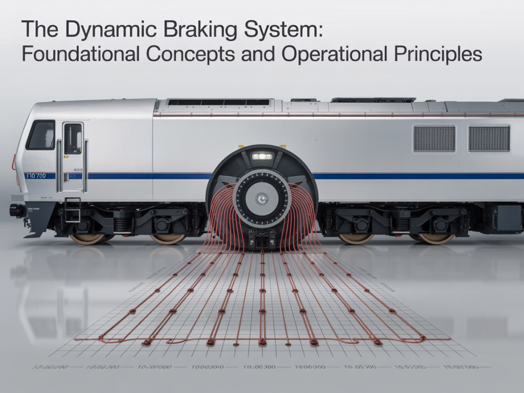
The operational principle underlying dynamic braking involves converting the traction motors from their normal role as electrical consumers into temporary electrical generators. When a locomotive operator engages the dynamic brake handle, the traction motors disconnect from the main alternator circuit and instead connect to the resistive grid network through the diesel engine’s remaining idle operation. As the locomotive’s wheels continue to rotate while the prime mover idles, the traction motors physically generate electrical current proportional to their rotational velocity.
This generated current flows through the dynamic brake resistor grids, where it encounters resistance measured in fractions of an ohm, producing Joule heating that dissipates the locomotive’s kinetic energy. The control systems carefully regulate the current flowing through these grids, typically limited to approximately 700 amperes in standard-capacity EMD dynamic braking configurations, preventing damage to resistive elements or electrical components through excessive current flow.
The advantages of dynamic braking extend far beyond simple speed control. This system enables smoother and more efficient operation, minimizing wear and tear on mechanical parts compared to friction-only braking. The efficiency and reliability of diesel-electric locomotives, which have effectively replaced older propulsion methods in freight and passenger service, rest substantially upon their sophisticated electrical transmission systems that include dynamic braking as an integral component. Particularly on long mountain grades where repeated heavy braking demands occur throughout a shift, dynamic braking capabilities significantly reduce locomotive maintenance costs and extend the service life of friction brake components.
Integration with Diesel-Electric Locomotive Architecture
The dynamic braking system cannot be understood in isolation from the broader diesel-electric locomotive architecture. In these sophisticated vehicles, the diesel engine does not directly drive the train’s wheels through mechanical gears and clutches as in traditional automobiles or older steam locomotives. Instead, the engine operates as a prime mover generating electricity that powers electric traction motors connected to the wheels. This electrical transmission system offers greater mechanical efficiency and flexibility compared to direct mechanical transmission alternatives. The diesel engine can operate at its most efficient speed point without regard to locomotive speed, as the electrical transmission system automatically compensates through generator voltage and current adjustments.
The process of power generation and transmission in diesel-electric locomotives follows a well-defined sequence. The diesel engine converts chemical energy from diesel fuel into mechanical energy through piston motion driven by controlled combustion. This mechanical energy drives an electrical generator or alternator, which converts mechanical rotation into electrical energy that can be transmitted through wires to distant traction motors. For efficient control, the electrical generator initially produces alternating current (AC) electricity that is then rectified into direct current (DC) before distribution to traction motors. The control systems manage the amount and timing of power delivered to traction motors based on operational demands, throttle position, and feedback from various locomotive sensors.
During dynamic braking operation, this entire process reverses in controlled fashion. The traction motors, now rotating due to locomotive momentum while the engine idles, generate electrical current that flows backward through the control systems into the resistor grids rather than forward to the power supply. This design ensures that regenerative energy cannot damage the alternator or other electrical components, providing inherent safety through the system architecture itself.
The locomotive’s speed and the mechanical gearing between wheels and traction motors determine the voltage generated, with typical maximum dynamic brake effectiveness occurring between 19 and 23 miles per hour depending on gear ratios. Below five miles per hour, dynamic braking becomes increasingly ineffective as the voltage generated drops below the threshold needed to produce meaningful braking force.
The Dynamic Brake Resistor Grid System: Architecture and Function
Structural Design and Physical Configuration
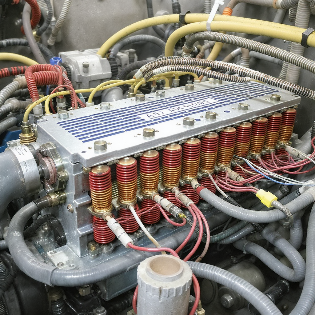
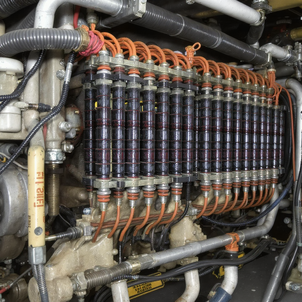
The dynamic brake resistor grids visible on modern locomotives represent sophisticated assemblies designed to repeatedly absorb high-energy electrical pulses while maintaining dimensional stability across extreme temperature variations. Grid resistors employ stainless steel resistance elements arranged in accordion-like folds that maximize surface area for efficient heat dissipation. These steel ribbons are held in position within a containment box through round steel studs welded to the outer and inner folds of the accordion configuration. The studs pass through ceramic supports that maintain proper spacing and prevent electrical shorting between adjacent resistance elements, a critical design feature preventing catastrophic failure.
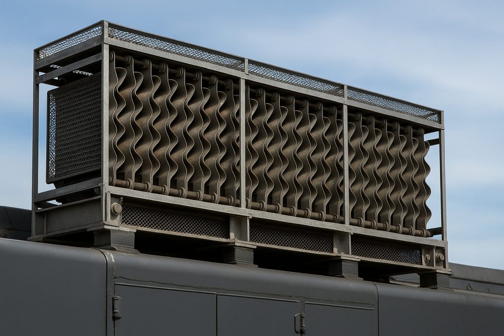
Ceramic supports occupy a particularly important position in the overall resistor grid design, as they must balance two seemingly contradictory requirements. The supports must remain sufficiently rigid to maintain precise spacing between resistance ribbons, preventing physical contact that would cause electrical short circuits and localized melting. Simultaneously, these supports cannot be rigidly fixed to the grid box, as they must allow thermal expansion of the resistance ribbons when resistor grids reach operating temperatures of several hundred degrees Fahrenheit. This engineering compromise, achieved through precision ceramic materials and careful mechanical design, represents one of the critical innovations distinguishing modern locomotive dynamic braking systems from earlier, simpler designs.
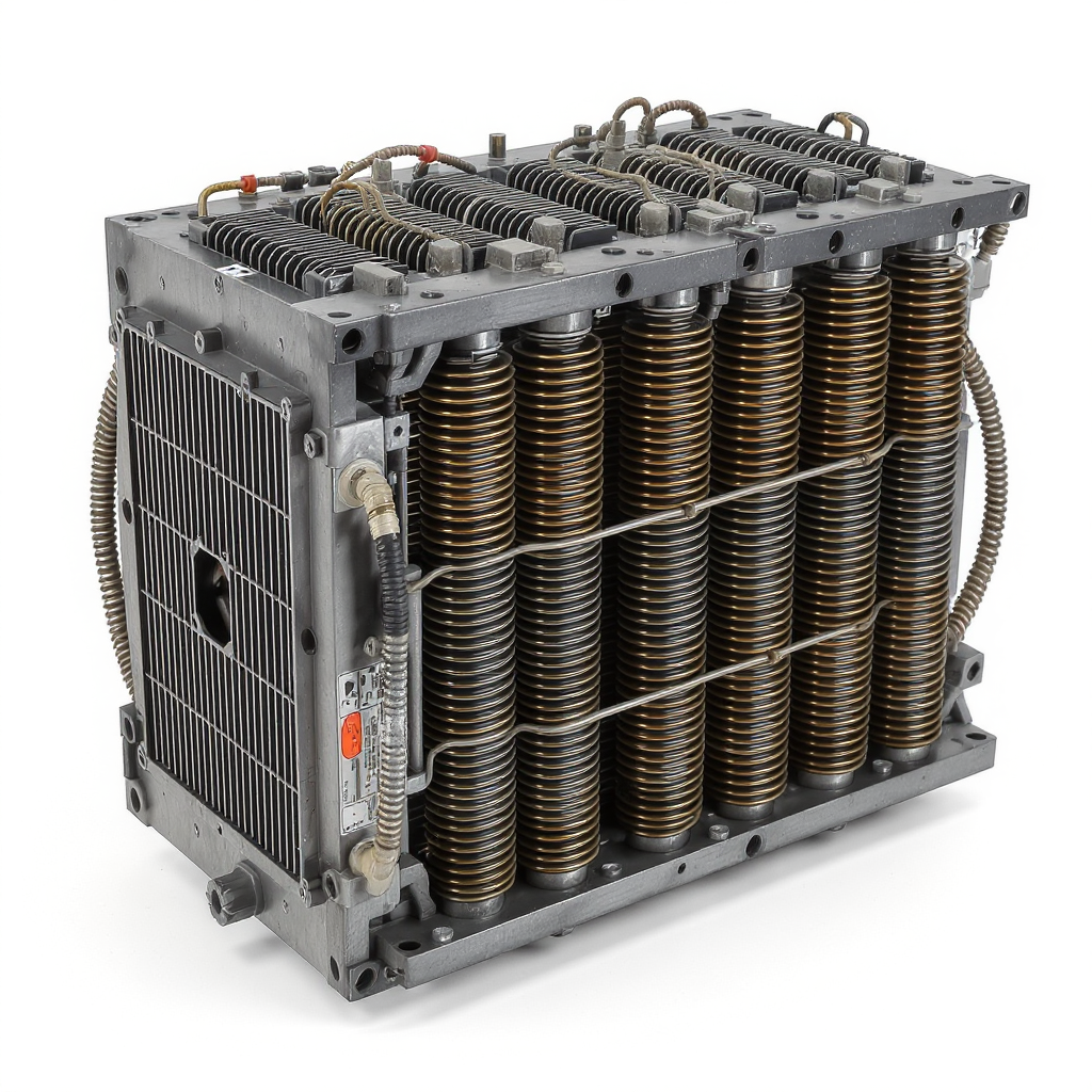
A complete dynamic brake grid assembly consists of several individual grid boxes mounted within a structural frame and interconnected through bus bars or cables that provide the total grid resistance required for proper circuit operation. On four-axle locomotives with a single truck, one grid box connects to the blower fan motor, while the remaining boxes operate as pure resistance elements.
Six-axle locomotives, more common in heavy-haul service, feature two grid boxes connected to fan motors, with additional boxes providing resistance-only function. Grid boxes not serving as fan boxes maintain standardized resistance values of 0.43 ohm in EMD standard-capacity dynamic braking systems. Those grid boxes incorporating blower fan motors incorporate higher resistance values that, combined with the blower motor in parallel, produce the same total resistance as the pure resistance boxes through careful electrical design.
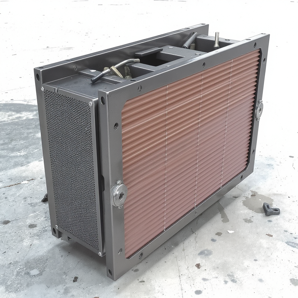
Thermal Management and Cooling Systems
The cooling system represents an absolutely critical component of dynamic braking system performance and reliability. During heavy braking events, resistor grids dissipate enormous amounts of thermal energy, with temperatures rising to several hundred degrees Fahrenheit within seconds. Without adequate cooling airflow, the resistor elements can overheat, leading to premature failure and potential damage to surrounding locomotive structures. Modern locomotives employ forced-air cooling through dedicated blower fans specifically designed to circulate ambient air across the resistor grid surfaces at high velocity.
The physical location of dynamic brake resistor grids has evolved substantially as locomotive designs have progressed, reflecting engineering lessons learned about thermal management. Early locomotives incorporated dynamic brake grids in prominent blisters mounted directly above the diesel engine, positioned immediately adjacent to hot exhaust manifolds and engine surfaces. This proximity to the engine heat source created problematic thermal conditions, with resistor grids absorbing unwanted heat from the engine through radiation and conduction, reducing overall cooling efficiency and potentially shortening component life. In response to these thermal management challenges, modern locomotive designs, including those featuring the EMD 710 engine, relocated dynamic brake grids to positions further from the prime mover.
On SD50, SD60, and SD70M-class locomotives, dynamic brake resistor grids are positioned immediately behind the cab and in front of the central air intake, completely separating them from the direct influence of engine heat. Modern SD70M-2 and SD70ACe locomotives push the grids even further to the rear of the long hood, positioning them behind the radiators where ambient air flows around and through the resistor elements with maximum efficiency.
This evolution demonstrates how ongoing operational experience and thermal analysis informed successive locomotive generations, continually improving component reliability and service life. The GP60, notably, represents the first, last, and only 710-powered EMD locomotive to retain the original above-engine blister location for dynamic brakes, likely reflecting the physical constraints of the smaller GP platform that limited design flexibility.
EMD Parts 10634215 and 10634216: Specific Function and Technical Specifications
Hardware Component Classification and Purpose
EMD parts 10634215 and 10634216 represent mounting hardware specifically designed for dynamic brake resistor grid assemblies, though detailed technical specifications for these exact part numbers appear limited in readily available public documentation. Drawing from available information about ALCO (American Locomotive Company) grid box configurations that utilize these same or similar part numbers, these components function as bracket geometry and fastener assemblies that secure resistor grid boxes within their mounting frames. The distinction between part number 10634215 and 10634216 involves bracket geometry and fastener stack heights, reflecting design variations that accommodate different locomotive platforms and mounting configurations.
Part number 10634216 suits locomotive frames with revised standoff spacing, representing a newer design iteration that reflects engineering improvements or manufacturing tolerance adjustments. Part number 10634215, conversely, fits earlier locomotive mounting configurations with shorter offsets, preserving compatibility with legacy locomotives while accommodating updated manufacturing specifications. This design approach, maintaining dual part numbers for related assemblies, reflects the railroad industry’s emphasis on backward compatibility while simultaneously enabling design improvements. Each hardware kit preserves proper airflow lanes and resistor alignment, critical factors that directly impact cooling efficiency and thermal performance.
The specific application of these parts within the EMD 710 system context requires understanding that they function as precision fastening hardware rather than electrical components themselves. While these parts do not directly conduct current or dissipate energy, their precise specification and correct installation directly determines whether the dynamic braking grid achieves optimal thermal management and electrical performance. Using incorrect or mismatched hardware could skew the dynamic braking grid orientation, raising temperatures at terminal joints and lugs, potentially compromising electrical connections and accelerating component degradation. Proper installation requires matching the specific part number 10634215 or 10634216 as originally specified for each locomotive model, ensuring that thermal expansion characteristics and mechanical alignment remain within design parameters.
Integration with Overall Dynamic Braking Architecture
The EMD 710 locomotive series incorporates dynamic braking systems that depend upon precise mechanical alignment and thermal management to function reliably. Within this context, the relatively small mounting hardware represented by parts 10634215 and 10634216 assumes critical importance. During dynamic braking operation, electrical current flowing through the resistor grids generates heat at rates proportional to the current squared, a relationship known as Joule heating. Standard-capacity EMD dynamic braking systems limit current to approximately 700 amperes, producing enormous thermal loads that must be distributed evenly across all resistance elements.
The mechanical fastening hardware represented by these part numbers maintains precise spacing between resistor ribbons and proper orientation within the grid box. This precision proves essential because uneven spacing would create localized regions of higher current density, producing concentrated heat generation that could exceed material temperature limits. The ceramic supports mentioned previously depend upon the fastening hardware to maintain correct positioning, a design interdependency that demonstrates how even small components contribute substantially to overall system function.
Temperature cycling during normal locomotive operation creates additional stresses on mounting hardware. When resistor grids heat to operating temperatures, the steel ribbon elements expand, creating internal stresses that the fastening hardware must accommodate while maintaining precise spacing. Upon cooling, the elements contract, requiring that fastening hardware maintain original spacing without allowing ribbon displacement or contact. Material selection for these components emphasizes high-temperature tolerance, with fasteners typically manufactured from stainless steel or other materials exhibiting minimal thermal expansion over wide temperature ranges. This careful material engineering ensures that fastening hardware maintains dimensional stability throughout the operating envelope.
Comparative Analysis: EMD Versus Competing Systems
The dynamic braking hardware specifications developed by EMD for the 710 engine platform differ substantially from those incorporated in competing locomotive lines manufactured by General Electric and others. The ALCO grid box, utilizing similar part number designations like 10634215 and 10634216, features different bracket geometries and mounting specifications reflecting ALCO’s unique locomotive frame designs and thermal management approaches. These differences are not merely cosmetic variations but represent fundamental engineering choices about how resistor grids integrate with their respective locomotive platforms.
Grid resistor technology itself exhibits substantial standardization across the locomotive industry, with stainless steel resistance elements providing reliable high-energy pulse absorption across diverse applications. Vishay Milwaukee Resistor manufactures grid resistors in standard configurations with resistance ranges from 0.25 ohm to 50 ohm, power ratings from 4,000 watts to 24,000 watts, and low inductance specifications from 10 microhenries to 40 microhenries. However, the mounting hardware and integration methodology vary substantially between manufacturers, reflecting different locomotive platform requirements and design philosophies. Railway braking resistors employed in high-speed train applications operate at substantially higher voltages (25 kilovolt in some international applications) compared to domestic North American locomotives, necessitating completely different hardware approaches and safety specifications.
Electronic Control Systems and Operational Integration in EMD 710 Locomotives
Engine Control Architecture and Electronic Governors
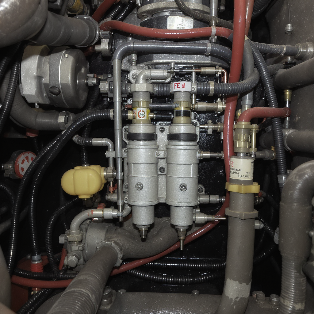
The EMD 710 engine platform represents a fundamental shift toward electronic control compared to earlier purely mechanical systems. Unlike the 645 and earlier 567 series, which employed mechanically-controlled unit injectors, the 710 incorporates electronically-controlled unit injectors (EUI) that enable sophisticated engine management impossible with mechanical systems. These electronically controlled fuel injectors maintain camshaft-driven pressurized fuel delivery but control the timing of injection operations through the engine control unit, achieving significant advantages in emissions performance, fuel economy, and operational flexibility.
The function of electronically-controlled unit injectors depends upon sophisticated electronic control systems that monitor engine speed, load, throttle position, and other operational parameters in real time. At the heart of each injector lies a built-in plunger pump that provides exceptionally high-pressure fuel delivery and atomization to the combustion cylinder.
A solenoid-operated spill valve controls fuel flow, normally remaining open to allow fuel recirculation to the supply line during the plunger descent phase. When the control unit energizes the solenoid, the spill valve closes, forcing pressurized fuel through the spray tip into the cylinder at precisely the moment required for optimal combustion. This electronic precision enables multiple injection events per combustion cycle, fine-tuned fuel delivery timing, and adaptive operation across diverse load and environmental conditions.
The EMD 710 engine employs various governor systems to maintain engine speed within safe operating parameters despite changing load conditions. Governors represent mechanical or electronic devices that control the amount of fuel injected into cylinders, maintaining engine speed within predetermined operating ranges. Early diesel engine governors operated purely mechanically through fly-weight mechanisms that responded to centrifugal force, but modern locomotives increasingly employ electronic governors that provide superior control, diagnostic capabilities, and fail-safe operation. When throttle demands increase, governors automatically increase fuel injection rates, causing engine speed to increase. When load decreases, governors reduce fuel injection, preventing dangerous overspeeding.
Dynamic Brake Control Interface with Engine Management Systems
The integration of dynamic braking systems with electronic engine management in EMD 710 locomotives represents one of the more sophisticated aspects of modern locomotive operation. When an operator engages the dynamic brake handle, the engine control system must immediately shift the traction motor circuits from normal power generation mode to regenerative braking mode while maintaining engine speed stability at idle operation. This transition requires coordinated action between multiple subsystems including the main alternator, traction motor contactors, dynamic brake resistor grid circuits, and engine speed governing systems.
The control systems continuously monitor electrical parameters including voltage, current, and temperature during dynamic braking operation to ensure safe, efficient energy dissipation. Should dynamic brake current exceed the designed maximum (typically 700 amperes in standard EMD configurations), the control system automatically reduces the braking intensity to prevent resistor grid damage. Some locomotives feature audible and visible warnings that alert operators when current approaches maximum safe levels. All locomotives equipped with dynamic braking incorporate grid blower failure detection systems that monitor fan motor operation and alert crews if cooling airflow drops below safe levels. These protective systems embody a design philosophy emphasizing fail-safe operation where component failures trigger graduated warnings rather than catastrophic system failures.
The EM2000 Control System and Modern Locomotive Electronics
Progress Rail documents that the EMD EM2000 Control System represents “the only microprocessor-based system in continuous use for over 16 years,” reflecting the long service life and reliability of this advanced platform. This control system coordinates all major locomotive functions including engine speed regulation, fuel injection timing, dynamic brake operation, electrical power distribution, and safety monitoring. The microprocessor-based approach enables sophisticated algorithms that would be impossible to achieve through mechanical or analog electronic means, including load-sharing between multiple generators in distributed power consists, regenerative energy capture during braking, and predictive fault detection.
Modern EMD 710 locomotives incorporating the EM2000 system represent the pinnacle of diesel-electric locomotive technology, with electronic controls managing literally thousands of operating parameters simultaneously. The system continuously adjusts engine fuel injection rates to match load demands with minimal lag, optimizes turbocharger boost pressure for maximum efficiency, coordinates traction motor torque distribution across multiple axles, and manages dynamic braking intensity based on load weight and speed. This level of control sophistication directly addresses the challenge of maintaining locomotive voltage and current within acceptable ranges throughout the entire operating speed envelope, a problem that plagued early diesel-electric designs and motivated the transition system innovation discussed in technical literature.
The “Weak Link” Philosophy and Dynamic Brake Grid Design Principles
Safety Through Controlled Component Failure
One of the most important design principles underlying dynamic brake resistor grids in EMD locomotives involves deliberately making them the “weak link” in the dynamic brake circuit. This seemingly counterintuitive approach actually represents sophisticated safety engineering. Dynamic brake grids are intentionally designed and specified to fail before faults in dynamic brake regulation or blower motor failures would result in serious damage to traction motors, switchgear, or locomotive electrical cabling. In essence, the grids function as the system “fuse,” sacrificing themselves to protect more expensive and critical components.
This design philosophy emerged from operational experience where inadequate current limiting protection allowed dynamic brake faults to damage traction motors or electrical cabling, often resulting in complete locomotive failure requiring expensive depot-level repairs. By making the resistor grids the failure point, designers ensured that even catastrophic dynamic brake failures would result in grid degradation requiring grid replacement rather than major component damage. Replacement of dynamic brake grids represents a routine maintenance operation costing thousands of dollars but requiring only a few hours of crew time. By contrast, traction motor damage could result in depot repairs costing tens of thousands of dollars and removing the locomotive from service for weeks or months.
The mechanical design of dynamic brake grid assemblies incorporates this weak-link principle through multiple features. The accordion-folded steel ribbon design provides relatively thin cross-sectional area in the current path, creating natural current concentration. The ceramic supports allow ribbon thermal expansion without rigid constraint, permitting protective movement rather than resisting forces. The electrical connection points, using bolted lugs and bus bars, represent potential failure modes that degrade more gracefully than would occur if current flowed through welded connections that might catastrophically tear. Every design aspect reflects the philosophical commitment to controlled, graceful degradation rather than sudden catastrophic failure.
Monitoring and Failure Detection Systems
Modern EMD 710 locomotives incorporate comprehensive failure detection systems specifically monitoring dynamic brake grid conditions and performance. All locomotives equipped with dynamic braking feature grid blower failure detection that continuously monitors fan motor operation during dynamic braking intervals. Should airflow drop below safe levels, warning systems alert the locomotive crew that cooling has become inadequate. Some modern locomotives employ temperature sensors embedded within the resistor grid assembly that provide real-time thermal monitoring. When grid temperature approaches preset limits, control systems automatically reduce dynamic brake current to prevent equipment damage.
Electrical monitoring systems continuously observe current flow through dynamic brake circuits, comparing actual current to values expected based on locomotive speed and gear ratios. Should current exceed expected maximum values, indicating possible short circuits or other faults, the control system progressively reduces dynamic brake intensity while alerting the crew to the fault condition. This graduated response approach prevents sudden, uncontrolled loss of braking capability that could create dangerous situations on steep grades while simultaneously limiting the damage scope. The operator can usually continue operating at reduced dynamic brake intensity while arranging to have the locomotive inspected and repaired at convenient maintenance facilities rather than immediately losing all braking capability.
Maintenance, Troubleshooting, and Service Protocols for Dynamic Brake Grids
Routine Inspection and Preventive Maintenance Requirements
Proper maintenance of dynamic brake resistor grids extends component life and maintains system reliability, requiring routine inspection, correct torqueing, and timely cleaning. Operators and maintenance personnel should visually inspect dynamic brake grids during regular maintenance intervals, examining for visible damage, loose connections, or excessive corrosion on mounting hardware and electrical terminals. Proper airflow remains absolutely critical, requiring that mounting hardware holds grids in correct position and that cooling vent passages remain clear of debris or obstructions. Dust accumulation on resistor surfaces reduces cooling efficiency, potentially degrading thermal performance and accelerating component aging.
The specific hardware components represented by parts 10634215 and 10634216 require verification that all bolts remain tight and lock wires remain in place, not loose or broken. Springs, where employed in the mounting hardware, must not show visible damage from impact or fatigue. If the dynamic brake system has experienced catastrophic failure, some railroads elect to replace the spring drive gear assembly during turbocharger overhaul, a precaution that eliminates potential future failures from gear wear or damage.
Torque specifications for dynamic brake grid mounting hardware must be carefully observed, as insufficient torque allows vibration-induced loosening while excessive torque can strip threads or deform ceramic supports. Maintenance documentation should precisely specify the correct torque values and fastener material specifications for each locomotive model.
Temperature Management and Operating Condition Monitoring
Operators must monitor dynamic brake system performance indicators during regular operation, noting any changes in fan noise or visual indicators suggesting cooling system problems. The locomotive’s gauge panel typically displays current flow through dynamic brake circuits, allowing crews to observe if current reaches abnormally high levels suggesting possible short circuits or improper system function. Maximum dynamic brake strength typically occurs at speeds between 19 and 23 miles per hour, depending on traction motor gear ratios, with effectiveness decreasing substantially at lower speeds. Experienced operators recognize these speed-dependent characteristics and plan braking strategies accordingly, maximizing dynamic braking effectiveness during the speed ranges where it operates most efficiently.
Proper airflow and tight connections remain vital to dynamic brake grid reliability, with overheating and cracked elements representing common failure modes. The mechanical structure must remain extremely resistant to vibrations inherent in freight train operations, with proper shock absorption and flexible mounting arrangements preventing mechanical damage from coupling shocks and track irregularities. The resistance material typically employs stainless steel providing least resistance change with temperature, ensuring that thermal stability of the resistance values allows predictable braking force across wide temperature ranges. Operating personnel should report any unusual conditions including excessive noise from the dynamic brake fan, visible cracks or damage to the grid enclosure, or sparking visible through fan openings suggesting internal arcing or short circuits.
Common Failure Modes and Troubleshooting Approaches
Operators commonly encounter dynamic brake resistor grid failures through several predictable failure mechanisms requiring systematic troubleshooting and repair approaches. Overheating represents perhaps the most common failure mode, typically resulting from inadequate cooling airflow caused by blower fan failure, blocked vent passages, or improper grid positioning. Cracked resistance elements develop when thermal stresses exceed material limits, typically following years of service with many heating and cooling cycles. Loose connections at terminal lugs cause excessive resistive heating at the connection point, potentially creating visible sparking or melting of lug material. These failure modes are generally progressive, developing gradually over time rather than occurring suddenly, allowing preventive maintenance to catch problems before complete failure occurs.
The modular design of dynamic brake grid assemblies facilitates maintenance and repair. Individual grid boxes can be removed and replaced without disturbing the entire system, allowing crews to isolate problems to specific modules. If one grid box develops internal short circuits, replacement of that module restores dynamic braking capability while allowing diagnostic evaluation of the failed component. This modularity reflects EMD’s commitment to minimizing locomotive downtime and enabling field-level repairs with readily available parts and basic tools. The electrical interconnections between grid boxes use bolted bus bars or cables rather than welded connections, permitting relatively simple component replacement without specialized equipment or extensive labor.
Electromagnetic and Electrical Specifications of Dynamic Brake Systems
Current and Voltage Relationships in Dynamic Braking Operation
The fundamental electrical relationships governing dynamic brake system performance depend upon Ohm’s Law and power calculations basic to electrical engineering. The relationship expressed as E = IR indicates that voltage drop across the resistor equals the product of current flowing through it multiplied by its resistance. For standard-capacity EMD dynamic brake systems with grid resistance approximately 0.43 ohm and maximum design current of approximately 700 amperes, the resistor dissipates electrical power according to the formula P = I²R, producing approximately 210 kilowatts of thermal power at maximum current. This substantial power generation occurs within a very small space, requiring sophisticated cooling systems and precise engineering to prevent localized overheating.
The multiple grid boxes connected in parallel within a complete dynamic brake assembly operate to distribute current across multiple resistive paths rather than forcing all current through a single element. A locomotive with six grid boxes, for instance, divides 700 amperes into approximately 117 amperes per box, distributing heat generation much more evenly than would occur in a single large resistor.
This parallel configuration approach enables the use of relatively modest component sizes while handling enormous total power, a design principle reflecting the practical constraints of fitting sophisticated cooling systems within existing locomotive carbodies. However, the parallel connection approach requires careful electrical balance to ensure current distributes evenly; if one grid box develops higher than expected resistance due to internal corrosion or loose connections, current will concentrate in lower-resistance paths, creating the overheating conditions discussed in failure analysis sections.
Resistor Grid Electrical Performance Specifications
The dynamic brake resistor grid specifications must be carefully verified when replacing failed components to ensure electrical and thermal equivalence with original equipment. Verification requires checking resistance values, power dissipation rating in watts or kilowatts, maximum continuous and peak current ratings, physical dimensions, terminal configuration, and cooling requirements. Resistance values must fall within tight tolerance bands as specified by EMD, typically within plus-or-minus five to seven percent of the nameplate value. Deviations from specification indicate possible internal corrosion, fatigue cracking of ribbon connections, or incomplete manufacturing, any of which could compromise dynamic braking performance.
The enclosure ratings must also match original specifications to ensure proper protection against environmental contamination and maintain adequate electrical isolation. Grid resistors employ resistance ranges from 0.25 ohm to 50 ohm depending on application, with power ratings spanning from 4,000 watts to 24,000 watts in industrial locomotive applications. Low inductance specifications typically range from 10 microhenries to 40 microhenries, reflecting the need to minimize reactive components in the circuit that could cause undesirable oscillations or voltage transients. The specific resistor grid employed in each locomotive model undergoes rigorous testing to verify performance across the full operating envelope, ensuring predictable braking characteristics across the complete range of speeds and load conditions.
Technological Advancements and Future Directions in Locomotive Propulsion
Hybrid and Alternative Propulsion Technologies
The railroad industry currently investigates alternative and hybrid propulsion technologies that could supplement or eventually replace traditional diesel-electric designs, with implications for how future locomotives might employ dynamic braking systems. Industry reports indicate that hybrid locomotive use can result in fuel savings of 30 to 50 percent compared to conventional diesel-electric operation, reflecting the substantial efficiency gains possible when regenerative braking captures energy that traditional systems dissipate as heat. Battery-electric and diesel-battery hybrid locomotives represent the primary focus of current development efforts, with several North American railroads operating pilot fleets of these advanced locomotives on select routes.
In hybrid locomotive configurations, dynamic braking grids would serve a modified role within the overall energy management strategy. Rather than dissipating braking energy entirely as heat as in conventional dynamic braking, hybrid systems could redirect captured regenerative energy into battery storage systems for later use. This approach multiplies the efficiency gains from regenerative braking by preserving energy that would otherwise be lost. However, this transition would require substantial redesign of dynamic brake control systems and electrical architecture, potentially modifying the role of components like parts 10634215 and 10634216 in future locomotive generations.
Emissions Reduction and Environmental Compliance
The EPA Locomotive Emissions Comparison Tool documents emissions performance for modern EMD 710-powered locomotives compared to alternative propulsion technologies, reflecting the ongoing evolution of environmental standards and technology. Modern diesel-electric locomotives powered by EMD 710 engines represent the cleanest conventional diesel-electric designs available, incorporating sophisticated emissions control systems and fuel injection optimization. However, even these advanced conventional locomotives generate more emissions per ton-mile of cargo than alternative technologies including electrified railroads and emerging hydrogen fuel cell designs.
The dynamic braking systems employed in diesel-electric locomotives contribute substantially to environmental performance by reducing wear on mechanical brake components and minimizing energy waste during braking operations. By converting kinetic energy into controlled heat dissipation within resistor grids rather than generating dust and pollutants through friction braking wear, dynamic braking represents an environmentally preferable technology compared to mechanical braking alone. Future emission reduction strategies will likely emphasize regenerative energy capture and storage, positioning dynamic braking as part of a comprehensive energy recovery system rather than a simple energy dissipation device.
Integration and Significance of EMD Components 10634215 and 10634216
The EMD parts 10634215 and 10634216, while appearing to represent small, relatively insignificant hardware components, actually occupy a critical position within the sophisticated electromagnetic and thermal management systems of modern EMD 710 locomotives. These mounting hardware assemblies maintain precise spacing and alignment of dynamic brake resistor grids that dissipate enormous amounts of electrical energy during normal braking operations, protecting the locomotive’s traction motors and electrical system from damage through the intentional weak-link design philosophy. The specific engineering embedded in these part numbers reflects decades of operational experience and continuous improvement in locomotive design, enabling reliable, efficient operation under the demanding conditions characteristic of heavy-haul freight service.
Understanding the function of parts 10634215 and 10634216 requires examination of multiple interconnected systems including the EMD 710 engine’s turbocharger architecture, electronic control systems, dynamic braking principles, resistor grid design, thermal management approaches, and failure detection methodologies. These components cannot be understood as standalone items but rather as integral elements within a highly integrated propulsion and braking system designed to safely and efficiently move heavy trains across North America. The evolution from mechanical fastening approaches to today’s sophisticated mounting hardware reflects the broader progression of locomotive technology from mechanical governors and mechanical governors to electronic engine management and computer-controlled operating systems.
The railroad industry continues to invest in technology improvements that build upon the proven EMD 710 platform while simultaneously exploring alternative propulsion technologies including hybrid-electric and battery-electric designs. Within this evolving technological context, the principles embodied in dynamic brake resistor grid design and the mounting hardware that maintains proper grid function remain relevant even as specific implementations evolve. Future locomotive generations may employ different specific resistor arrangements or thermal management approaches, but the fundamental principle of deliberately designing components to fail safely before more critical elements suffer damage will likely remain central to locomotive reliability and safety philosophy.
For locomotive operators, maintenance personnel, and railroad engineers responsible for fleet management, understanding the role and maintenance requirements of dynamic brake systems proves essential for safe, reliable locomotive operation. Proper attention to routine inspection, correct torque application, and timely replacement of worn components ensures that dynamic braking systems continue functioning as designed throughout the locomotive’s service life. The relatively modest investment in preventive maintenance of components like parts 10634215 and 10634216 pays substantial dividends in avoiding costly locomotive failures, minimizing service interruptions, and preserving the safe operation of heavy trains carrying cargo and passengers across North America’s railroad network.
References:
https://en.wikipedia.org/wiki/EMD_710