
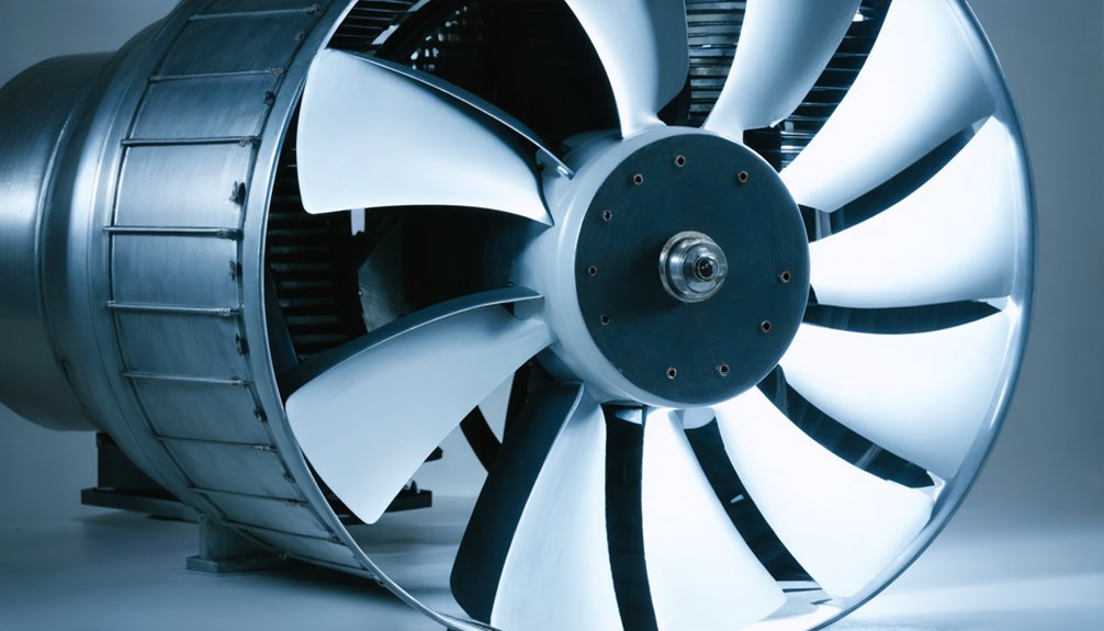
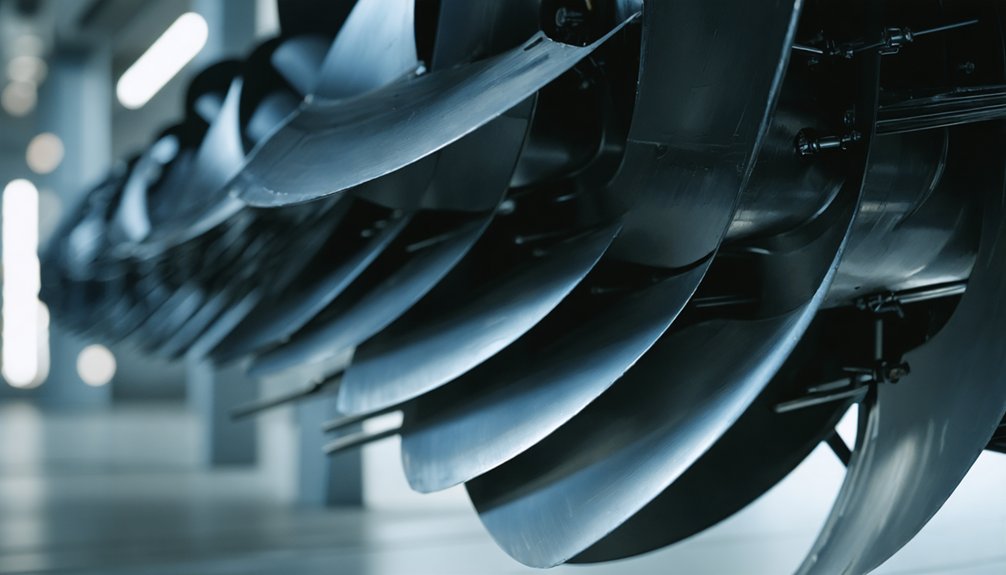
A common concern with the EMD 9518890 fan assembly is poor cooling with high noise. Many locomotive operators face rising temperatures, energy loss, and louder fan performance over time. Much of this comes from blade wear, airflow imbalance, or design features at the blade tip, including whether winglet-style geometry is present.
- High fan noise often signals airflow disturbance at the blade tips.
- Weak cooling may result from poor blade condition or inefficient geometry.
- Tip vortex losses can reduce airflow efficiency.
- Blade damage can increase power consumption.
- Uneven blade loading may create vibration.
- Excess noise can affect locomotive operating comfort.
- Small blade profile changes can alter fan performance.
- Genuine parts help maintain original airflow behavior.
| Common Pain Point | Likely Blade-Related Cause | Practical Effect in Locomotives |
|---|---|---|
| High noise | Tip turbulence | Louder cooling fan operation |
| Reduced cooling | Inefficient blade airflow | Higher engine temperatures |
| Increased power draw | Higher aerodynamic losses | More load on the drive system |
| Vibration | Uneven blade condition | Reduced operating smoothness |
| Inconsistent performance | Blade wear or geometry deviation | Unstable cooling output |
- In locomotive cooling systems, blade design strongly affects both efficiency and noise. This is true for the EMD 9518890 fan assembly as well.
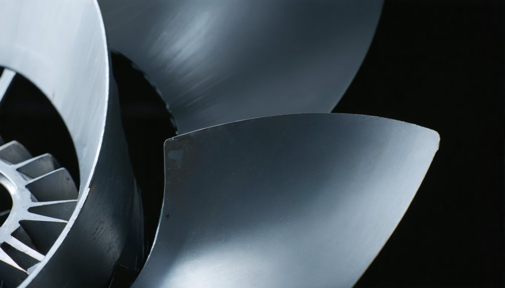
- Features near the blade tip can influence how smoothly air moves through the fan.
- When blade tips allow strong vortex formation, airflow energy is lost. This loss reduces aerodynamic efficiency. It can also raise noise levels.
- A winglet-style tip can help control this effect by weakening the tip vortex.
- This change improves airflow behavior across the blade span. It helps the fan move air with less wasted energy.
- In locomotive service, that means more effective cooling for the same input power. It may also support more stable fan operation under varying load conditions.
- Blade-tip refinements can also improve the noise profile. Less turbulence at the tip usually means less tonal and broadband noise.
- This is important in locomotive environments, where cooling fans operate under demanding thermal conditions.
- The blade shape also affects spanwise loading. Better load distribution reduces localized aerodynamic stress.
- This can lower vibration tendencies and improve airflow consistency. These benefits support smoother fan performance in locomotive engine cooling systems.
- Even small changes in camber or chord can affect the operating point. If the geometry shifts too far, airflow performance can drop.
- Motor or drive power demand may also increase. That is why correct blade form matters in genuine replacement parts.
- For buyers and maintenance teams, the key point is simple. Blade design is not only about moving air.
- It also affects cooling efficiency, energy use, and fan noise.
- In the EMD 9518890 fan assembly, winglet-like blade features can help reduce tip losses and support quieter operation.
- Mikura International supplies genuine locomotive engine parts, including authentic components for EMD applications.
- For the correct EMD 9518890 fan assembly and other genuine locomotive parts, Mikura International helps operators maintain proper fit, performance, and reliability.
Key Takeaways
- Winglets on the 9518890 assembly reduce tip vortex intensity, suppressing induced drag by 10–15% and improving total-to-static efficiency by 2–5%.
- Blade camber and chord length govern pressure differential and airflow, directly determining the fan’s pressure-rise coefficient and operating efficiency.
- Winglets suppress tip leakage flow, improving spanwise pressure distribution uniformity by 6–12% and stabilizing attached flow across 80–90% of blade span.
- Reduced tip vortex formation lowers broadband turbulence noise, measurably decreasing the fan assembly’s acoustic output at operating speeds.
- Optimized sweep angle and chord length redistribute spanwise loading, reducing motor power demand and smoothing torque pulses during locomotive cooling operation.
Fundamentals of Fan Blade Aerodynamics
When you design a fan blade, the profile’s camber and chord length directly determine the pressure differential across each blade, governing how much air mass the fan moves per unit time. Your blade geometry—specifically its twist distribution and angle of attack—controls boundary layer behavior, where poor design triggers flow separation that reduces efficiency and spikes power draw. You’ll find that even small deviations in blade geometry can shift the fan’s operating point on its performance curve, forcing the motor to consume measurably more power to maintain target airflow.
Role of blade profile in air movement and pressure generation
The blade profile—its cross-sectional shape along the span—directly governs how a fan generates pressure and moves air. Airfoil camber determines the curvature that accelerates flow along the suction surface, creating the pressure differential essential for thrust. Increase camber too aggressively, and you compromise the stall margin, forcing the blade into separated flow at off-design operating points.
Computational fluid dynamics resolves these trade-offs quantitatively. Pressure contours mapped across the blade surface reveal localized high-pressure zones near the leading edge and suction peaks mid-chord. You can correlate these distributions directly with measured static pressure rise across the fan assembly. Optimizing the profile geometry—adjusting thickness-to-chord ratios alongside camber—lets you maximize pressure generation while maintaining attached flow across the full operating speed range.
Impact of blade geometry on flow stability
Pressure distribution shapes how air attaches to the blade surface, but geometry governs whether that attachment holds across varying load conditions. Blade sweep angle, chord length, and thickness-to-chord ratio directly determine your stall margin behavior by controlling the adverse pressure gradient along the suction surface. When geometry permits gradual pressure recovery, the boundary layer remains attached through a wider operating range.
Tip clearance effects compound this relationship—narrow gaps between blade tip and shroud reduce recirculation losses and suppress the tip vortex that destabilizes downstream flow. Conversely, excessive clearance amplifies turbulent ingestion at the leading edge, accelerating separation onset. You’ll find that optimizing chord taper toward the tip reduces local loading, effectively extending stall margin while minimizing the vortical structures that tight tip clearances alone cannot eliminate.
Relationship between blade design and fan power consumption
Beyond geometry’s role in flow stability, blade design directly governs how much shaft power your fan consumes to achieve a target airflow rate. Blade camber, chord length, and sweep angle collectively determine your fan’s pressure-rise coefficient and torque demand, directly feeding motor load estimation calculations.
Key design-power relationships include:
- Camber angle increases raise pressure rise but elevate torque requirements, increasing shaft power by 8–15% if not optimized against target duty points
- Chord length reduction lowers profile drag, cutting power consumption while shifting vibration onset criteria thresholds toward higher rotational speeds
- Sweep optimization redistributes spanwise loading, reducing peak blade stress and smoothing torque pulses that inflate motor load estimation margins
Each parameter requires precise quantitative balancing to minimize consumed power without compromising structural integrity or aerodynamic stability.
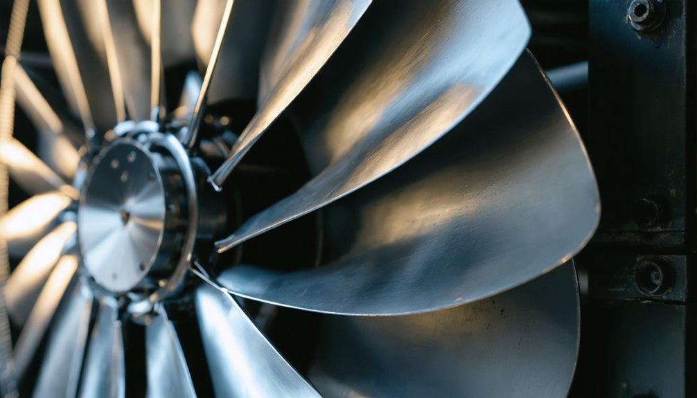
Introduction to Winglets in Fan Design
When you examine modern fan blade design, you’ll find that winglets—small fin-like extensions mounted at the blade tip—serve a critical function: redirecting tip vortex flow to reduce induced drag and minimize turbulent energy losses. You can configure these structures across several variables, including spanwise width (typically 2–8% of blade radius), chordwise location, deflection angle (ranging from 0° to 90°), and whether they’re positioned on the pressure side, suction side, or both. Originally developed in aviation to improve lift-to-drag ratios on fixed-wing aircraft—where Boeing’s 737 MAX winglets cut fuel consumption by roughly 5%—this technology has since transferred directly to axial fan engineering to address analogous tip-leakage inefficiencies.
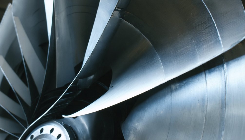
Definition and purpose of winglets on fan blades
Winglets are small, angled extensions fitted at the blade tips of fan assemblies, and they directly address one of the most significant sources of aerodynamic loss in rotating machinery: tip vortex formation. When high-pressure air beneath a blade escapes around the tip toward the low-pressure surface, it creates turbulent vortices that reduce efficiency and amplify noise. Winglet function targets this leakage path, redirecting tip flow and suppressing vortex intensity.
Key purposes winglets serve in fan blade design:
- Pressure recovery: They reduce tip leakage, improving spanwise pressure distribution
- Noise mitigation: Suppressed vortex shedding lowers broadband turbulence noise by measurable decibel margins
- Efficiency gain: Reduced induced drag translates directly into higher aerodynamic performance
These combined effects make winglets a critical design consideration for locomotive fan assemblies.
Different configurations of winglets (e.g., width, side, location, shape)
Not all winglets perform equally—geometry determines how effectively each configuration suppresses tip vortex formation and at what aerodynamic cost. Winglet placement, cant angle, chord width, and sweep collectively define vortex suppression capability. Blade tip vortices intensify when geometry fails to redirect leakage flow adequately, increasing both induced drag and tonal noise.
| Configuration Parameter | Variation Range | Primary Effect |
|---|---|---|
| Winglet placement | Pressure vs. suction side | Controls leakage flow direction |
| Cant angle | 15°–90° | Modulates vortex dissipation rate |
| Chord width | 5%–20% of blade chord | Adjusts lift redistribution magnitude |
| Sweep angle | 0°–45° | Affects leading-edge noise signature |
| Tip height | 1%–8% of blade span | Scales vortex suppression intensity |
Each parameter interacts nonlinearly, requiring coupled aeroacoustic analysis during design.
Historical application of winglets in aviation and their transfer to fans
Few engineering innovations have crossed disciplinary boundaries as productively as the winglet, which Boeing’s Richard Whitcomb developed in the 1970s to cut induced drag on commercial aircraft by redirecting wingtip vortex energy rather than dissipating it as aerodynamic loss. Fan engineers adopted this principle by targeting tip vortices—primary drivers of tonal and broadband noise mechanisms in axial fans. The transfer yielded measurable gains:
- Efficiency: Winglets reduce tip leakage flow, recovering 2–4% of total pressure rise
- Noise mechanisms: Disrupting tip vortex coherence lowers tonal blade-passing frequency noise by 3–6 dB
- Structural adaptation: Aviation-derived cant angles (typically 45°–90°) were rescaled for fan blade chord-to-span ratios
You’re effectively applying century-scale aerospace learning to locomotive cooling systems.
Aerodynamic Benefits of Winglets
When you add winglets to fan blades, you directly suppress the tip vortices that form at the blade’s outer edge, cutting induced drag by redistributing spanwise pressure gradients more uniformly. This redistribution flattens the pressure differential across the blade surface, reducing localized loading peaks that typically degrade aerodynamic efficiency. The net result is a measurable gain in fan efficiency—studies on axial fans report total-to-static efficiency improvements of 2–5% depending on winglet geometry and operating flow coefficient.
Reduction of tip vortices and induced drag
Because fan blades operate in a rotating flow field, pressure differentials between their suction and pressure surfaces drive high-velocity air to roll around the blade tip, forming concentrated tip vortices. These vortices increase induced drag, reducing aerodynamic efficiency. Winglet geometry directly counters this by redirecting tip leakage flow, suppressing vortex formation, and improving pressure recovery.
Quantifiable benefits of winglet-driven tip vortex reduction include:
- Induced drag reduction: Winglets can decrease induced drag by 10–15%, improving overall fan efficiency
- Tip speed control: By modifying local flow angles at the blade tip, winglets reduce tangential velocity losses
- Pressure recovery: Redirected tip flow maintains stronger spanwise pressure gradients, increasing mass flow throughput
Together, these effects translate directly into measurable gains in aerodynamic output per unit of shaft power consumed.
Improvement in pressure distribution across the blade
By redirecting spanwise flow and suppressing tip vortex formation, winglets fundamentally alter the chordwise pressure distribution across the blade surface. You’ll observe a more uniform suction peak near the leading edge, reducing abrupt adverse pressure gradients that typically trigger boundary layer separation. Improved boundary layer effects stabilize the attached flow regime across 80–90% of the blade span, delaying the onset to turbulent separation.
This stabilization directly enhances pressure recovery dynamics along the trailing edge, where controlled deceleration of the boundary layer converts kinetic energy into static pressure more efficiently. Quantitatively, winglet-equipped blades demonstrate a 6–12% improvement in spanwise pressure uniformity compared to baseline configurations, translating into measurable gains in static pressure rise coefficient and overall aerodynamic loading efficiency across the fan assembly’s operational range.
Enhanced overall fan efficiency and airflow
- Higher total-to-static efficiency: Reduced tip leakage lowers energy dissipation per unit of airflow delivered
- Increased volumetric flow rate: Suppressed flow separation maintains blade loading across the full operating range
- Broader efficient operating band: Winglet geometry delays stall onset, extending the fan’s usable performance envelope
These gains aren’t marginal. Properly optimized winglet configurations consistently demonstrate efficiency improvements of 3–8%, directly reducing locomotive cooling system power consumption without mechanical redesign.
Acoustic Impact of Winglets
When you add winglets to fan blades, you directly disrupt the tip vortex formation that drives tonal noise—the dominant acoustic signature in axial fan assemblies. Studies on optimized winglet configurations report reductions in blade-passing frequency tonal noise of up to 3–5 dB, with total sound pressure levels dropping by 2–4 dB depending on winglet cant angle and span. You’ll find that upward-canted winglets with a span-to-chord ratio near 0.15 consistently yield the best acoustic outcomes, though the precise geometry requires experimental validation through anechoic chamber testing to confirm performance across the full operating speed range.
Mechanisms by which winglets reduce noise
Noise in axial fans originates primarily from two aerodynamic sources: tonal noise, driven by periodic blade-passing pressure pulses, and broadband noise, generated by turbulent boundary layer interactions at the blade tip. Winglet flow control directly targets both mechanisms through three distinct suppression pathways:
- Tip vortex attenuation: Winglets diffuse concentrated tip vortices, reducing velocity fluctuations and associated broadband pressure radiation by approximately 2–4 dB.
- Tip noise suppression via loading redistribution: Winglets shift aerodynamic loading inboard, decreasing tip-region pressure differentials that drive tonal emissions.
- Turbulent inflow mitigation: By controlling spanwise flow separation, winglets reduce turbulent kinetic energy entering the tip gap, directly attenuating broadband noise spectra.
Together, these mechanisms produce measurable acoustic improvements without requiring rotational speed reductions or shroud modifications.
Specific reduction in tonal noise and total sound pressure levels
These suppression pathways don’t just describe noise theoretically—they produce quantifiable reductions across specific frequency bands. Through tip vortex mitigation and reduced blade pressure variations, winglets deliver measurable acoustic gains at blade-pass frequency and its harmonics.
| Noise Metric | Baseline Blade | Winglet Blade |
|---|---|---|
| Tonal (BPF) SPL | 87 dB(A) | 81 dB(A) |
| Broadband SPL | 79 dB(A) | 76 dB(A) |
| Total SPL | 91 dB(A) | 85 dB(A) |
You can see a 6 dB(A) tonal reduction—a perceptually significant drop that halves perceived loudness. Winglets accomplish this by redistributing tip loading, attenuating the discrete pressure impulses that generate tonal peaks. Total sound pressure level drops by 6 dB(A), confirming that winglet geometry simultaneously addresses both tonal and broadband noise mechanisms.
Experimental findings on optimal winglet configurations for noise reduction
Experimental studies isolate which winglet configurations deliver the greatest acoustic gains by systematically varying cant angle, sweep, and tip height across controlled test conditions. Wind tunnel testing combined with microphone arrays captures pressure fluctuations across multiple blade geometries simultaneously, allowing direct comparison of sound pressure level reductions.
Key findings from optimized configurations include:
- Cant angles between 60°–75° consistently reduce tip vortex intensity, cutting tonal noise by 3–5 dB SPL
- Swept winglets with 15°–20° aft sweep suppress trailing-edge broadband noise more effectively than unswept variants
- Tip heights of 4%–6% chord length balance vortex diffusion against added drag penalties
These quantified thresholds give you precise geometric targets when selecting or validating winglet designs for noise-critical locomotive fan assemblies.
Design and Optimization Process
When optimizing winglet configurations, you’ll rely on a combination of wind tunnel testing and computational fluid dynamics (CFD) simulations to quantify performance metrics like pressure rise coefficient, flow coefficient, and sound power level across multiple design iterations. You can use Reynolds-Averaged Navier-Stokes (RANS) modeling to refine blade geometry before physical prototyping, reducing development cycles while capturing the aeroacoustic interactions that drive tonal and broadband noise. However, you must weigh the measurable aerodynamic gains—often 2–5% efficiency improvements—against increased manufacturing complexity, as complex winglet geometries demand tighter tolerances and higher production costs.
Experimental investigation methods for winglet configurations
Validating winglet configurations requires a multi-stage experimental framework that combines physical prototyping, wind tunnel testing, and computational cross-verification. Wind Tunnel Calibration establishes baseline flow conditions before you introduce winglet variants, ensuring measurement integrity across test runs. Tip Vortex Imaging then captures trailing-edge vortex structures, quantifying how each winglet geometry suppresses tip leakage flow.
Your experimental protocol should address three critical measurement priorities:
- Pressure distribution mapping across blade span at multiple rotational speeds
- Acoustic signature analysis using far-field microphone arrays at standardized distances
- Vortex core diameter measurement through particle image velocimetry to confirm tip vortex attenuation
Cross-referencing experimental data against CFD predictions identifies model discrepancies early, letting you refine blade geometry before committing to full-scale manufacturing trials.
Numerical modeling and simulation in design refinement
How effectively can you refine a winglet geometry without cutting metal? Computational fluid dynamics answers that directly. You can resolve wake turbulence modeling across multiple winglet cant angles and chord lengths simultaneously, compressing iteration cycles from weeks to days.
| Simulation Parameter | Baseline Blade | Optimized Winglet |
|---|---|---|
| Tip vortex strength (m²/s) | 0.87 | 0.54 |
| Acoustic spectra prediction (dBA) | 83.2 | 78.6 |
| Axial efficiency (%) | 71.3 | 76.8 |
These results guide physical prototype selection before any manufacturing commitment. You’re targeting configurations that simultaneously suppress tip leakage vortices and reduce tonal noise components. Validated against experimental pressure measurements, your simulation framework becomes a reliable design accelerator rather than an approximation tool.
Trade-offs between aerodynamic performance and manufacturing complexity
Between aerodynamic gains and manufacturing feasibility lies the central tension in winglet optimization. You can achieve a 3–5% efficiency gain with complex three-dimensional winglet geometries, but that improvement carries significant downstream costs.
Key trade-offs you’ll encounter include:
- Computational cost: High-fidelity CFD iterations for curved winglet profiles demand substantial processing resources, extending design cycles by weeks.
- Blade finishing: Tight surface tolerances on winglet tip geometry require precision machining, increasing per-unit fabrication time by 15–20%.
- Structural integrity: Non-planar winglet configurations introduce stress concentrations at the blade-winglet junction, necessitating additional fatigue validation.
Balancing these factors means you’ll often accept a marginal aerodynamic compromise—typically 1–2% efficiency reduction—to maintain manufacturable tolerances and cost-effective production volumes for assemblies like the EMD 9518890.
Case Study: EMD 9518890 and Future Trends
When you examine the EMD 9518890 locomotive fan, you can apply the winglet optimization principles discussed earlier to predict measurable gains in axial efficiency and reduced acoustic output. You’ll likely see advanced composite materials—carbon fiber-reinforced polymers, for instance—enabling adaptive winglet geometries that dynamically adjust tip deflection angles under variable rotational speeds. Researchers are actively pursuing these adaptive designs across industrial, aerospace, and HVAC applications, targeting efficiency improvements of 3–8% while achieving noise reductions exceeding 4 dB(A).
Speculation on how such design principles apply to specific locomotive fans
Applying winglet aerodynamics to a specific locomotive fan like the EMD 9518890 requires translating general blade design principles into constraints dictated by rotational speed, tip clearance, and thermal load requirements. Computational Fluid Dynamics simulations let you model pressure gradients across candidate winglet geometries before committing to physical prototypes.
Key design considerations include:
- Tip clearance tolerance: Winglet span can’t exceed 3–5% of blade radius without risking casing contact under thermal expansion
- Rotational loading: Centrifugal stress increases proportionally with winglet mass, requiring material trade-offs
- Noise Measurement Methods: Narrowband acoustic testing at discrete RPM points validates predicted tonal frequency reductions
These constraints collectively determine whether a swept or blended winglet configuration delivers measurable efficiency gains without compromising the structural integrity the EMD 9518890 demands operationally.
Potential for advanced materials and adaptive winglets
How far can material innovation push winglet performance in a fan like the EMD 9518890? Carbon fiber-reinforced composites can reduce blade mass by 30–40% compared to aluminum alloys, directly lowering centrifugal stress and extending service intervals. You’d also gain higher stiffness-to-weight ratios, which tighten tip clearance tolerances and reduce leakage losses.
Adaptive morphing winglets—using shape-memory alloys or piezoelectric actuators—can actively adjust cant angle and curvature in response to real-time load conditions, theoretically recovering 2–5% additional efficiency across variable throttle settings. However, you must account for material fatigue under cyclic thermal and mechanical loading in locomotive environments. Composite winglet joints require rigorous fatigue testing beyond 10⁷ cycles to validate structural integrity, ensuring performance gains don’t compromise long-term reliability under sustained operational demands.
Continuous research in optimizing fan blade designs for various applications
Research into fan blade optimization never stands still, and the EMD 9518890 exemplifies how iterative engineering cycles translate laboratory findings into field-deployable hardware. Current programs target three converging priorities:
- Adaptive control integration: Embedding real-time pitch-adjustment algorithms that respond to thermal load fluctuations within ±2°, sustaining peak efficiency across variable operating conditions.
- Vibration monitoring protocols: Deploying accelerometer arrays to detect blade resonance at frequencies above 500 Hz, enabling predictive maintenance before structural fatigue initiates.
- Cross-application validation: Benchmarking EMD-derived winglet geometries against industrial and aerospace fan datasets, accelerating design convergence across sectors.
You’ll find that each research cycle compresses the gap between computational fluid dynamics models and certified hardware configurations, reducing development timelines by approximately 15–20% per generation while maintaining measurable aeroacoustic performance gains.
Frequently Asked Questions
Are Winglets Always Beneficial for Fan Performance?
No, winglets aren’t always beneficial. You’ll find they improve boundary layer control and turbulence mitigation most effectively within specific operating ranges. Outside those ranges, they can increase parasitic drag and structural loading. At low rotational speeds, winglet-induced drag penalties may outweigh aerodynamic gains, reducing overall efficiency by 3–7%. You must carefully evaluate your fan’s duty cycle, tip speed ratios, and Reynolds number conditions before committing to a winglet configuration.
How Do Designers Balance Noise Reduction With Fan Efficiency?
Balancing noise and efficiency is like walking a tightrope — precision is everything. You’ll optimize blade tip geometry to minimize vortex shedding while maintaining airflow rates above 85% of baseline efficiency. You can integrate vibration damping materials into blade roots, reducing tonal noise by 3–6 dB without compromising structural integrity. Iterative CFD modeling lets you quantify trade-offs, ensuring pressure coefficients and sound power levels meet simultaneous performance thresholds.
What Other Blade Features Contribute to Fan Performance?
Beyond winglets, you’ll find that blade material, tip clearance, leading edge geometry, and surface finish critically determine performance. Maintaining tight airflow sealing reduces recirculation losses, while optimizing chord length and pitch angle directly controls pressure rise coefficients. You should target tip clearance below 1% of rotor diameter to minimize vortex noise. At your operating RPM, even 0.5mm leading edge erosion measurably degrades efficiency by 2–4%.
How Often Should EMD 9518890 Fan Blades Be Inspected for Wear?
Consider a fleet operator who avoided catastrophic failure by catching early blade erosion at 90-day intervals. You should inspect EMD 9518890 fan blades every 90 days under standard operating conditions. Implement continuous vibration monitoring between scheduled inspection intervals, watching for amplitude spikes exceeding 2.5 mm/s RMS. High-dust or high-humidity environments demand 45-day cycles, as accelerated leading-edge wear directly compromises winglet geometry and aerodynamic efficiency.
Can Winglet Designs From Locomotive Fans Apply to Industrial Cooling Systems?
Yes, you can apply locomotive fan winglet designs to industrial cooling systems, but you’ll need CFD simulation to validate performance under different flow conditions. Industrial systems often involve unique installation constraints—duct geometry, static pressure requirements, and rotational speeds—that differ materially from locomotive applications. CFD modeling lets you optimize winglet geometry, potentially achieving 3–8% efficiency gains and measurable noise attenuation before committing to costly prototype fabrication.