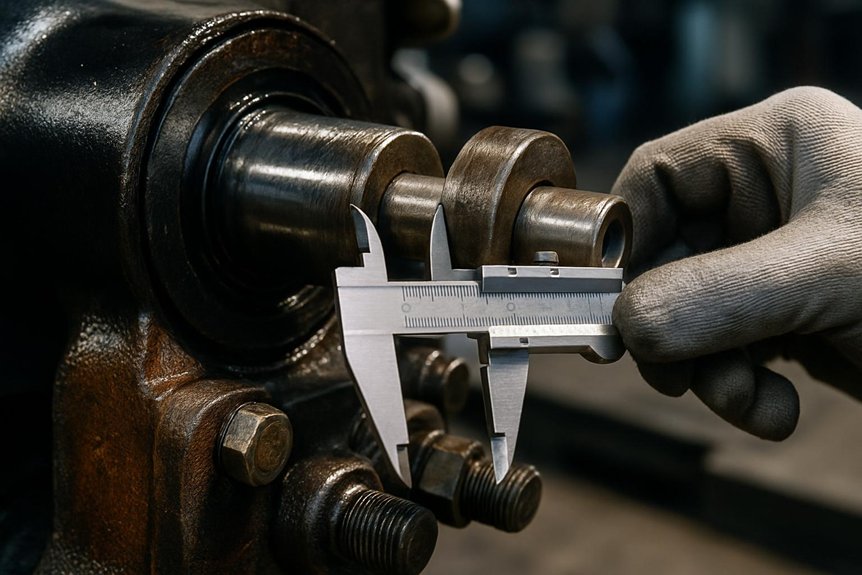
How the New Pantograph Dampers Make Stable Current Collection Epic

How the New Pantograph Dampers Make Stable Current Collection Epic

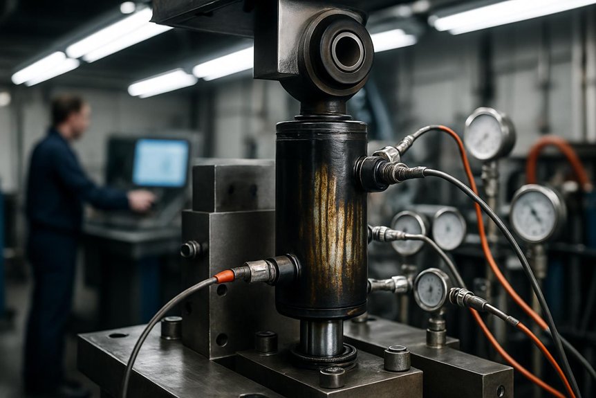
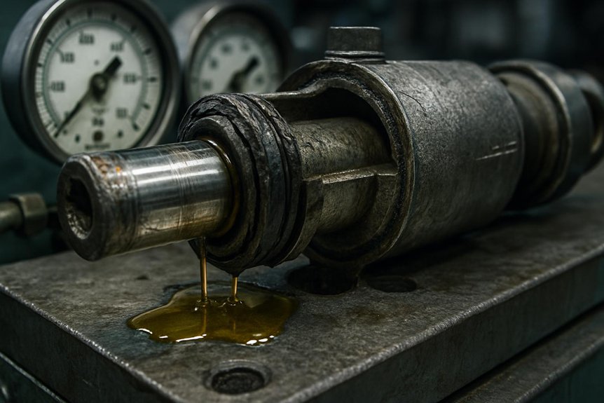
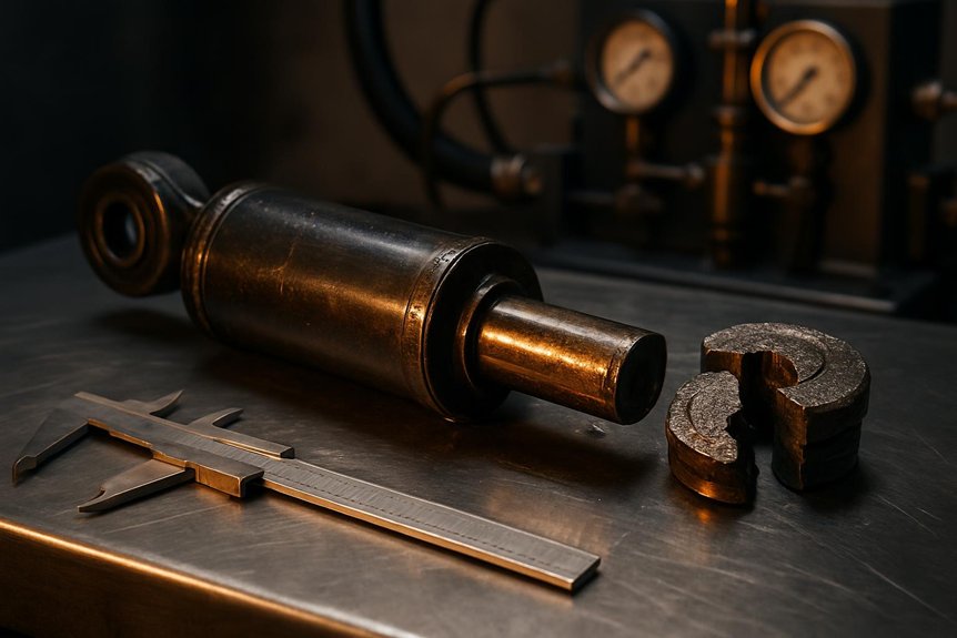
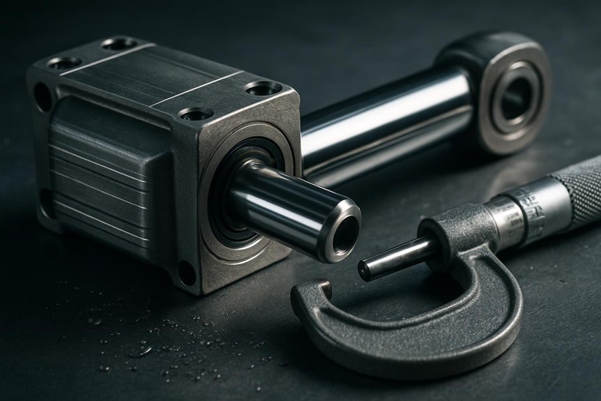
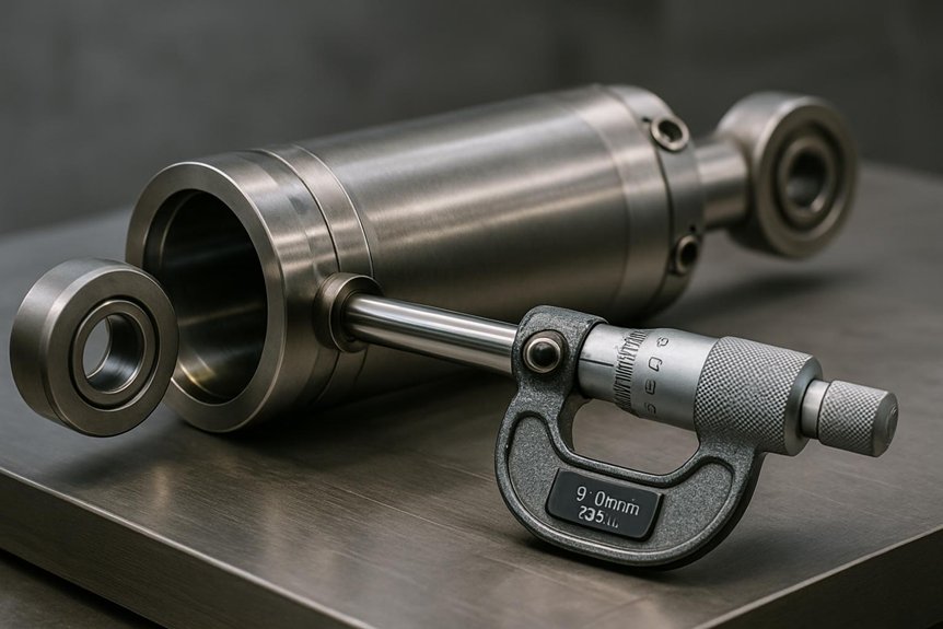
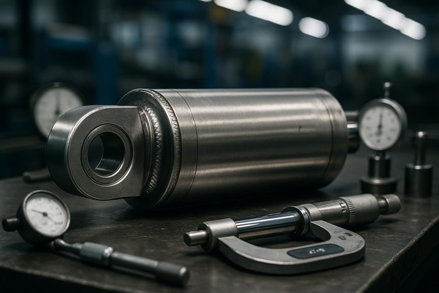
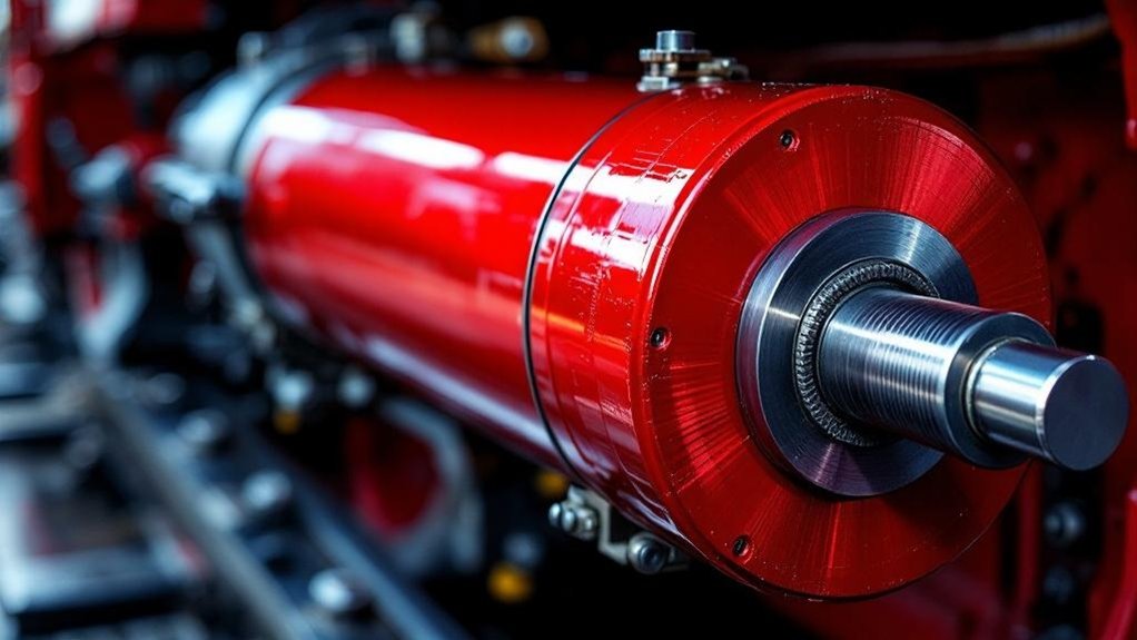
You don’t just need contact; you need unshakeable stability. Modern dampers instantly convert violent catenary wave energy into harmless heat, stopping destructive bounce before it snaps your connection. They maintain force within the narrow safe window, eliminating the millimetre gaps that trigger arcing and erosion. Smart semi-active systems even adapt damping in milliseconds for varying wire stiffness. The result is epic, uninterrupted current collection that protects your carbon strips and wire. The technology inside that slim cylinder is truly remarkable.

How do pantograph dampers ensure stable current collection in electric locomotives?

Pantograph dampers stop harmful vertical oscillations on the contact wire. Vibrations cause momentary contact loss and dangerous arcing. Dampers absorb this kinetic energy immediately.

Hydraulic or friction units keep the pantograph head within a precise force window. They prevent bouncing and maintain a stable sliding contact. This ensures uninterrupted electric power supply to the locomotive.

Stable current collection extends carbon strip and wire life. It reduces unscheduled maintenance and costly service delays. Engineers choose damper settings carefully for reliable high‑speed operation.

Key Takeaways

  • Smart dampers instantly convert violent pantograph motion into heat, preventing destructive rhythmic bounce.
  • Millisecond-response smart fluids adapt damping force to match varying catenary stiffness at over 300 km/h.
  • Real-time contact force tuning suppresses oscillations before they create arcing gaps and carbon strip erosion.
  • Active stabilization maintains force within the narrow safe window, preventing lift-off and micro-interruptions.
  • Predictive health monitoring uses vibration signatures to catch damper degradation early, maximizing infrastructure life.

Understanding the Dynamic Challenge at the Overhead Wire

control pantograph force range

You’re dealing with catenary waves that disrupt contact force and trigger harmful arcing. These disturbances cause momentary disconnections, eroding your carbon strip and wire. You must keep pantograph pressure inside a narrow range to stop energy loss and damage.

The Physics of Contact Loss and Arcing

A pantograph riding an overhead wire faces a chaotic mix of aerodynamic uplift, track vibrations, and wire elasticity. You’ll see contact loss when these forces exceed the pantograph dampers’ control range. Even millimetre gaps trigger destructive arcs, pitting the carbon strip. These arcs erode material and disrupt power. Railway overhead contact system dynamics demand precise force management. Without dampers, oscillations grow unchecked. The table below shows key separation triggers.

TriggerEffect on Contact
Aerodynamic upliftReduces downward force, lifting the head
Track vibrationsJar the pantograph, breaking smooth contact
Wire elasticityCauses vertical wave reflections, bouncing the strip
Combined transientsCreate arcing gaps, heating surfaces rapidly

You rely on dampers to absorb these forces instantly. They maintain stable contact and uninterrupted power, preventing arcs.

How Catenary Waves Disturb Current Collection

Contact loss and arc erosion don’t emerge at random. You face a dynamic challenge as your pantograph races along the wire. It pushes the wire up, creating travelling waves. Without damping, these waves reflect at supports. They return with force, slapping the pantograph head down. This bouncing disrupts your pantograph contact force control instantly. You lose precise upward pressure. The result is intermittent contact and arcing. Your electric locomotive power pickup stability crashes. Voltage fluctuates wildly, damaging onboard systems. You feel the surge and sputter. The overhead wire’s vibration becomes your primary enemy. It’s a constant battle against physics. You must tame these wire waves to maintain a steady connection.

The Critical Role of Contact Force Range

Unless your pantograph sustains contact force within a narrow band, arc erosion and wire wear escalate rapidly. You need understand how standards define static and dynamic force limits. Modern pantograph dampers confine forces inside this safe window. They prevent harmful lift-off and excessive pressure. This precision ensures stable current collection at any speed. Without it, you risk micro-interruptions that degrade carbon strips. Dampers absorb oscillations before they disrupt the contact point. You’ll see fewer arc events and extended wire life. Engineers select damper settings to match operating conditions exactly. Your entire network benefits from reliable power pickup. Stable current collection isn’t luck—it’s engineered force control.

How Pantograph Dampers Stabilise Power Pickup

controlled resistance dissipates energy

You need a system that converts violent motion into harmless heat, instantly. You’re using controlled resistance to dissipate energy without adding sluggish inertia to the collector head. This stops the pantograph from locking into a destructive rhythmic bounce with the catenary.

Energy Dissipation Through Controlled Resistance

Vertical oscillation strikes the pantograph head and dampers absorb that kinetic energy instantly. You see them convert violent motion into heat through controlled resistance. This process slashes oscillation amplitude dramatically. It reduces the panhead’s settling time after each catenary disturbance. Your contact force stays within a precise, stable window.

Unwanted bouncing ends almost as soon as it begins. You prevent the arcing that erodes carbon strips and contact wires. The damper’s resistive element provides a direct, mechanical path for energy escape. You avoid energy storage that could rebound into the system. This immediate thermal dissipation is your key defense. It ensures a continuous, unwavering electrical connection. Your electric locomotive draws smooth, reliable power. The infrastructure endures less mechanical stress and wear. You maintain operational harmony at any speed.

Maintaining Head Mass Under Control Without Adding Inertia

While lightweight pantograph heads respond quickly to catenary changes, they risk uncontrolled bouncing. You’re adding dampers to tame this without increasing mass. They provide vertical restraint so the head stays nimble yet locked onto the wire.

  • Cut unnecessary inertia, avoiding sluggish response to contact height variation.
  • Convert kinetic energy instantly, stopping flutter before lift-off occurs.
  • Maintain a consistent contact force envelope for stable power pickup.
  • Extend carbon strip life by eliminating hammering against the catenary.

Dampers let you exploit a low-mass design’s agility. You’re securing continuous current flow without dead weight penalising acceleration or wear.

Preventing Harmful Resonance with the Catenary

Because catenary wires naturally oscillate at specific frequencies, pantograph dampers prevent destructive resonance from building. You match damper stiffness and damping coefficient to avoid these resonant peaks. Tuned damping protects your railway overhead contact system dynamics across the whole speed range. You stop amplified motion that could break contact. Without this, pantograph contact force control fails, causing arc erosion. Your dampers absorb energy right at the troublesome frequencies. This ensures stable current collection and extends carbon strip life. You maintain ideal contact force through precise mechanical behaviour selection. It’s critical for high‑speed electric locomotive power pickup stability. Proper tuning prevents bouncing that damages wires and disrupts power. Your proactive damping design guarantees reliable performance over varying track conditions.

Types of Pantograph Dampers and Their Mechanisms

hydraulic vs friction pantograph dampers

You can choose from three main damper technologies for your locomotive’s pantograph. Hydraulic dampers offer precision and adjustability for high-speed demands. Friction dampers give you simple, robust control, while semi‑active and active systems future‑proof your operations.

Hydraulic Dampers – Precision and Adjustability

When you need precise control over pantograph contact force, hydraulic dampers offer speed-dependent damping through oil-filled cylinders and calibrated orifices. You’ll find they excel in smoothing catenary-induced vibrations across varying speeds. Their design lets you fine-tune the damping curve for consistent power pickup stability.

You can adjust these dampers to match specific overhead contact system dynamics:

  • Tailor orifice sizes to alter damping force versus velocity.
  • Select oil viscosity for temperature stability and response.
  • Set blow-off valves to limit peak forces during hard shocks.
  • Maintain them easily with predictable wear patterns.

This precision prevents arc erosion and extends carbon strip life. You’ll appreciate their serviceability in demanding electric locomotive operations. Engineers rely on them for reliable high-speed current collection.

Friction Dampers – Simple and Robust

For operations demanding sheer durability, friction dampers rely on disc or pad elements to deliver consistent Coulomb damping. You see this in heavy freight locomotives pounding through harsh weather. The pads clamp against a disc, converting vibration into heat immediately. This simple mechanism resists wear without fluid leaks. You don’t tune it for speed; it provides fixed resistance against oscillation. That steady force stops the pantograph from bouncing off the contact wire. Arc erosion shrinks, so carbon strips last longer. Maintenance crews inspect pad thickness during routine checks. You swap worn components fast, no specialized tools needed. This robustness cuts downtime in gritty, high‑mileage corridors. Your current collection stays stable with minimal fuss.

Semi‑Active and Active Dampers for Future‑Proof Operations

Friction dampers offer brute reliability, but high-speed lines need adaptive control. You’ll find semi‑active and active dampers using smart fluids to instantly adjust damping force. Electro‑rheological and magneto‑rheological systems respond in milliseconds. They read real‑time contact force data and suppress oscillations before arcing begins. This protects carbon strips and wiring.

  • Instant viscosity change from a controlled electric or magnetic field
  • Real‑time force tuning that matches varying catenary stiffness
  • Reduced contact loss and arc erosion at speeds over 300 km/h
  • Seamless integration with condition monitoring for predictive maintenance

You eliminate harsh bouncing and extend infrastructure life. These dampers future‑proof your high‑speed current collection without mechanical lag. You gain precise, dynamic control where friction alone falls short.

Engineering Considerations for Damper Selection and Setup

damper selection for locomotive modes

You’ll match damper speed ratings to your locomotive’s operating modes first. Next, you’ll weigh environmental durability against practical maintenance intervals for your route. Finally, check compatibility with existing pantograph frames to avoid costly retrofits.

Speed Ratings and Operating Modes

While a hydraulic damper excels at high-speed cruising, its performance curve changes completely under the frequent acceleration of suburban service. You must match the damper’s speed rating to your locomotive’s true duty cycle. A constant intercity sprint demands a flat, stable damping force. Stop-start commuter duty generates rapid oscillation changes you can’t ignore.

You’ll select the correct operating mode by evaluating these factors:

  • Maximum line speed and anticipated continuous running velocity
  • Service type: high-mileage express versus frequent-stop local
  • Multi-pantograph interference risking coupled resonant modes
  • Acceleration profiles dictating force rise-time requirements

Your procurement spec must mirror these real-world dynamics. Choosing a mismatched damper doesn’t just waste money. It invites contact loss and arcing right when traction current draw peaks.

Environmental Durability and Maintenance Intervals

In locomotive rooftop service, extreme temperatures, dust, and moisture attack damper seals. You’ll see hardened seals crack in freezing cold and soften in desert heat. Ingressing grit then scores internal pistons and rods. Consequently, contaminated hydraulic fluid loses its damping properties fast. You must thus prioritize dampers with labyrinth-style dust exclusions and IP69K-rated sealing. These designs extend maintenance intervals dramatically. Instead of quarterly teardowns, you’ll perform annual visual checks. You verify seal integrity and check the nitrogen pre-charge without roof-level disassembly. Downtime drops sharply. By selecting corrosion-resistant stainless steel bodies, you sidestep rust-induced seizures. Ultimately, these ruggedized units maintain precise pantograph contact force control across thousands of kilometers, slashing your whole-life service costs.

Compatibility with Existing Pantograph Frames

Beyond environmental hardening, damper performance hinges on precise integration with the pantograph frame. You must confirm the damper’s mounting geometry matches your frame’s existing brackets. Don’t assume direct interchangeability. Misalignment introduces parasitic friction that distorts contact force control. You’ll degrade your railway overhead contact system dynamics quickly.

Verify these engineering considerations before selection:

  • Check static and dynamic envelope clearances around the articulated frame.
  • Confirm the damper’s stroke length suits your pantograph’s maximum vertical travel.
  • Evaluate the inertial impact of a heavier semi-active damper on the head’s response.
  • Test the bolt hole diameters and bushing compatibility to prevent joint slop.

You’ll preserve designed electric locomotive power pickup stability. Never retrofit a damper that over-stresses the lightweight upper frame. You maintain precise pantograph contact force control through direct, stress-free mounting. This ensures your stable current collection strategy works perfectly.

Procurement, Testing, and Maintenance Best Practices

iec compliant vibration monitoring kpis

You need clear KPIs like damper force consistency and mean time between failures when you evaluate suppliers. Don’t overlook in‑service monitoring, where you track vibration signatures to catch degradation early. You must also verify that your testing aligns with IEC 62486 and EN 50367 for full compliance.

Key Performance Indicators for Supplier Evaluation

Although initial cost grabs attention, a pantograph damper’s performance data tells the real story for long-term stable current collection. You don’t just buy a component; you invest in contact force control. Assess suppliers using these key indicators:

  • Damping curves that match your speed range and catenary dynamics
  • Endurance test results proving lifecycle resilience under cyclic loading
  • Mean time between failures from real-world electric locomotive data
  • Compliance with IEC 62486 for consistent reaction force behaviour

These metrics reveal true value. They predict how well the damper suppresses vibrations, prevents arc erosion, and extends carbon strip life. You’ll avoid unscheduled maintenance. So, demand this data. It ensures your procurement decision delivers uninterrupted power pickup stability.

In‑Service Condition Monitoring Techniques

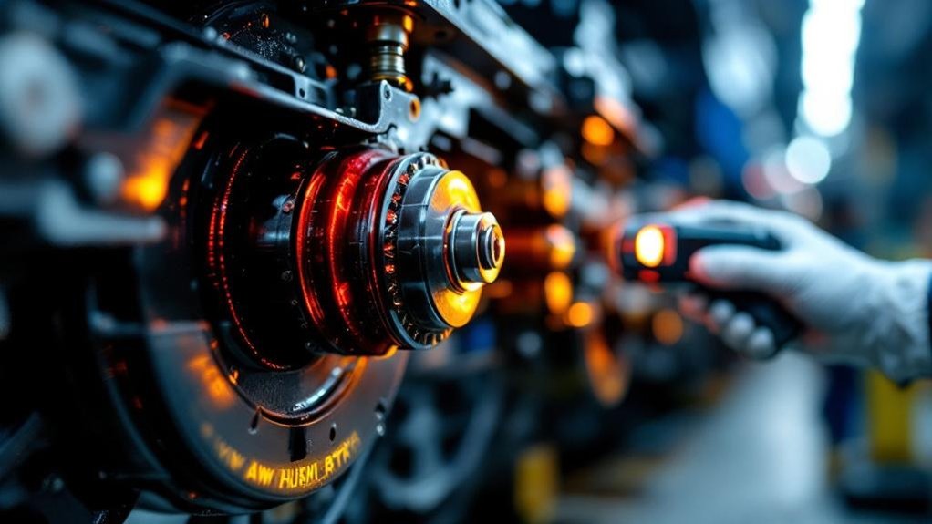
A healthy pantograph damper doesn’t announce itself—it quietly preserves stable current collection. You detect degradation early using thermal cameras. They reveal overheating from internal leakage or friction loss. Displacement sensors track erratic pantograph head motion in real time. You spot stiffness shifts before contact force control fails. These techniques prevent arcing and carbon strip damage. You schedule interventions based on actual wear, not fixed intervals. Predictive maintenance avoids unplanned outages and extends infrastructure life. You keep operations stable without disruptive surprises.

Compliance with International Railway Standards

Advanced condition monitoring reveals damper health, but procurement must commence with solid standards. You ensure your pantograph dampers meet IEC 62486‑1 and EN 50367 from day one. These norms define rigorous testing protocols for contact force control. You avoid interoperability failures and safety risks by requiring certified compliance. Your maintenance team then follows standardized inspection cycles. This strategy prevents arc erosion and extends infrastructure life. You’ll base every procurement decision on proven criteria:

  • Verify dynamic type‑testing reports under varied speeds.
  • Demand factory acceptance tests per EN 50367 limits.
  • Audit supplier quality plans for consistent damper performance.
  • Schedule routine service intervals matching manufacturer and standard guidelines.

You gain reliable, stable current collection through this disciplined approach.

Frequently Asked Questions

Can Damper Choice Reduce Electromagnetic Interference in Signalling Systems?

Ever worry about hidden gremlins messing with your signalling? Your damper selection directly reduces electromagnetic interference. You minimise arcing when hydraulic dampers maintain consistent contact force. A stable pantograph prevents the micro-breaks that create disruptive broadband emissions. Choosing the right friction damper smooths movement, stopping transient spikes. You quieten the electrical noise at its source, protecting adjacent communication cables. Ultimately, selecting dampers for improved contact stability ensures your traction power doesn’t corrupt track circuit signals.

Do Pantograph Dampers Affect Noise Levels for Trackside Communities?

Yes, your damper selection directly affects trackside noise levels. Vibrations from poor contact cause the pantograph head to chatter and arc. You hear this as a harsh, crackling sound. A well-tuned hydraulic or semi-active damper suppresses these oscillations. It keeps the carbon strip gliding smoothly, eliminating the dominant source of high-frequency screech and impulsive electrical noise reaching nearby communities.

What Training Do Maintenance Crews Need for Semi-Active Damper Diagnostics?

You’ll need training in reading real-time sensor data and interpreting control unit fault codes. You must learn to test electro-hydraulic valves and check accelerometer feedback loops. Your course should cover dynamic bench testing and correlation with onboard monitoring systems. You’ll practice identifying erratic damping profiles and software glitches. Master these skills, and you’ll quickly isolate failures that cause arcing and strip wear. Don’t skip hands-on troubleshooting with manufacturer diagnostic tools.

How Do Dampers Behave During Icy Conditions on the Contact Wire?

You’ll watch Mother Nature turn your contact wire into a frozen violin string, then watch your dampers laugh at her composition. Ice buildup creates stubborn vertical oscillations that force your pantograph head to skate instead of slide. Your damper immediately stiffens its resistance, absorbing those erratic jerks before arcing begins. It prevents the catastrophic bounce that welds ice to carbon strips. You avoid the spectacular light show of arc erosion while maintaining near‑static contact force through the crystalline chaos.

Can Damper Data Predict Remaining Catenary Life Before a Fracture?

You can predict remaining catenary life before a fracture. Your pantograph damper’s force data reveals excessive vibration patterns and impacts. These signatures directly correlate to wire fatigue and accelerated fretting. You track degraded damping, which flags escalating contact losses that notch and weaken the conductor. Analyzing this lets you forecast the critical wear point. You avoid a catastrophic fracture by spotting systemic damage early, all through the damper’s real-time acceleration and displacement feedback.

Why Vertical Dampers Make a Better Thrilling Ride for Loco Bogies

Why Vertical Dampers Make a Better Thrilling Ride for Loco Bogies

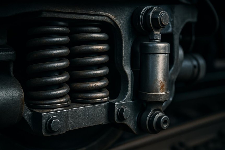
You feel that thrilling surge because vertical dampers convert violent axle-box motion directly into heat through velocity-dependent shim-stack metering. You get soft compression valving that rapidly absorbs track-joint shocks, paired with firm rebound damping that arrests wheel hop instantly. This asymmetrical tuning maintains consistent wheel-rail contact forces across bounce and pitch frequencies, preventing oscillation amplification that would otherwise make speed feel unstable. The engineering behind this force–velocity curve reveals why locomotives seem to glide.

How do vertical dampers differ from lateral dampers in locomotive bogie design?

Vertical dampers control bounce, pitch, and vertical vibrations. They mount between the bogie frame and axle box. This preserves wheel‑rail contact over track irregularities. Their stroke is tuned for vertical dynamic loads. This ensures stable ride comfort and reduces suspension wear.

Lateral dampers suppress sway and hunting oscillations. They are installed horizontally across the bogie or between bogie and carbody. These dampers absorb yaw moments at high speed. They prevent unstable lateral movements from growing. Their design targets self‑excited vibrations that threaten safety.

Vertical dampers react mainly to road‑induced inputs. Lateral dampers counteract kinematic instability. Vertical units affect dynamic wheel loads and comfort. Lateral units govern stability and curving behaviour. Their stiffness, mounting angles, and damping curves differ substantially. Engineers select each type for distinct frequency ranges and operational demands.

Key Takeaways

  • Vertical dampers absorb bounce and pitch vibrations by converting dynamic axle motion into heat through viscous oil flow.
  • Shim-stack valves deliver velocity-dependent damping that softens sharp impacts while maintaining body control.
  • Asymmetrical compression and rebound tuning rapidly dissipates track-joint shocks to create a smoother sensation.
  • Targeted energy dissipation across 0.5–10 Hz prevents oscillation amplification that would otherwise jolt passengers.
  • Firm rebound damping arrests wheel hop, keeping the sprung mass stable for a controlled, thrilling ride feel.

Fundamentals of Locomotive Bogie Dampers

Fundamentals of Locomotive Bogie Dampers

You control three damper classes in your bogie: vertical, lateral, and yaw. Vertical dampers manage axle motion through shim-stack valves that convert kinetic energy into heat. You tune each damper’s orifice stack for its specific dynamic mission without confusing ride comfort with stability.

Role of Dampers in Rail‑Vehicle Dynamics

Because dampers convert bogie vibration into heat, they’re the linchpin of locomotive suspension control. You rely on vertical dampers to absorb vertical dynamic loadspreventing excessive bounce and pitch. In locomotive suspension damping design, you select damping coefficients to manage energy dissipation across frequency ranges. This directly influences wheel‑rail forces and ride comfort. Without proper damping, oscillations amplify, degrading track friendliness and accelerating component fatigue.

You achieve stability by tuning hydraulic resistance to match suspension stiffness and unsprung mass. This precision ensures the bogie isolates carbody vibrations effectively. Dampers also suppress resonant modes that threaten operational safety. Therefore, your damping strategy defines the locomotive’s dynamic performance envelope. You always tailor damping curves to specific axle loads, ensuring consistent performance. This meticulous calibration protects wheel‑rail profiles.

Classification: Vertical, Lateral, and Yaw Dampers

While vertical dampers isolate the carbody from track-induced bounce, lateral dampers combat the self-excited sway and yaw that plague locomotive bogies. You exploit this classification to assign damping tasks precisely. Vertical units, mounted between bogie frame and axle box, absorb vertical shocks directly. They preserve wheel-rail contact over irregularities.

Lateral dampers locomotive bogies use horizontal mounting to suppress sway. Yaw damper mounting and tuning often combine with lateral designs, using specific bracket angles. This integration controls rotational hunting oscillations. You select each damper type for its targeted frequency range. Damping curves and stroke lengths differ markedly. The table below outlines these functional divisions. This delineation prevents cross-coupling of dynamic modes. You tune each damper to its operational demand. Proper classification ensures bogie stability.

Damper TypePrimary Motion ControlledMounting Configuration
VerticalBounceBetween bogie frame and axle box
LateralSwayHorizontally across bogie or to carbody
Yaw (often lateral)Rotational HuntingIntegrated with lateral dampers, tuned via bracket angles

Hydraulic Damping Principles and Shim‑Stack Valves

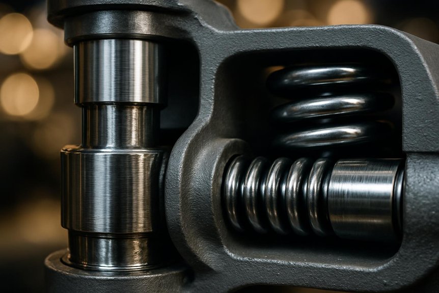
Hydraulic dampers convert kinetic energy into heat through viscous oil flow. You’ll observe shim‑stack valves metering this flow. Thin steel shims deflect progressively under pressure. This creates velocity‑dependent damping forceBlow‑off valves cap peak loads to protect seals. You tune the stack for specific damping characteristics. This directly aids bogie hunting stability control. It suppresses yaw oscillations from kinematic instability.

You design low‑speed bleed for ride comfort. High‑speed blow‑off limits excessive wheel force. Vertical dampers employ these principles in bounce mode. Their blow‑off setting avoids wheel load fluctuation. Lateral dampers use similar hydraulics for yaw suppression. You select oil viscosity for temperature compensation. Shim‑stack valves deliver reliable, repeatable performance. You rely on blow‑offs to cap hunting yaw moments. This ensures bogie hunting stability control.

Design and Mounting of Vertical Dampers

Design and Mounting of Vertical Dampers

You must define functional load cases by analyzing bounce frequencies and axle‑box acceleration spectra. You’ll mount the vertical damper directly between bogie frame and axle box, often using inclined linkages to match stroke angles. Then you tune the valve stack to generate a digressive damping curve that absorbs track impacts without spiking wheel‑rail forces.

Functional Requirements and Dynamic Load Cases

Vertical dampers face a tough assignment because they must absorb sharp shocks from track joints and wheel flats without losing control at low speeds. You see high-frequency impacts demanding prompt blow-off valve response. Yet you also require firm low-speed damping for bounce control. Dynamic load cases include temporary overloads from switches and dips. These impose velocities up to 1 m/s. Your damper’s relief valve must prevent force spikes above 15 kN. Concurrently, you tune the bleed circuit for a 0.1 m/s range. This ensures body motion control without harshness. Wheel-flat impacts repeat every rotation. You need robust seals and guides to survive this cyclic pounding. Proper thermal management handles energy dissipation from consecutive irregularities.

Typical Mounting Configurations and Linkage Geometry

After absorbing those punishing vertical loads, you must direct forces cleanly into the bogie structure. You’ll place vertical dampers near axle boxes for direct wheel‑rail feedback. Alternatively, you mount them between bogie frame and bolster to isolate the carbody. Your linkage geometry isn’t arbitrary; installation angles determine how much damping targets bounce versus pitch modes. A near‑vertical alignment emphasizes pure vertical control. A slight inclination introduces a modest pitch moment component, so you tune linkage lengths to avoid bind through full suspension travel. You’ll also ensure spherical bearings accommodate axle articulation. This precise geometry preserves damper stroke alignment, maximizing energy dissipation without side‑loading seals.

Valve Tuning for Ride Comfort and Wheel‑Rail Protection

Inside the damper body, you’ll tune compression and rebound valves asymmetrically.

  1. Soft compression valving reduces vertical impact forces quickly.
  2. Firm rebound damping arrests wheel hop, stabilizing sprung mass.
  3. This asymmetry curbs dynamic load variation, protecting rail and suspension.

You’ll select orifice and shim stacks to get digressive force‑velocity curvesCompression blow‑off yields low damping at high piston speeds, easing impact transfer. Rebound remains firm across velocities, preventing uncontrolled axle hop. This reduces wheel‑tread and rail‑head fatigue while preserving ride comfort. By precisely asymmetrical tuning, you’ll maintain consistent wheel‑rail contact forces across varied track inputs. Temperature‑compensating valves keep damping stable, so your bogie never loses its tune. Such valve calibration ensures ride comfort and protects wheel‑rail infrastructure. Soft compression also quiets secondary suspension chatter. It extends damper life.

Design and Mounting of Lateral Dampers

Design and Mounting of Lateral Dampers

You can’t ignore hunting oscillation—it’s a self-excited lateral instability that grows without damping and you integrate lateral dampers into the secondary suspension, often coupling them with anti-yaw bars to directly resist bogie rotation. You then select a damping ratio that effectively suppresses the yaw and sway modes without over-stiffening curving behaviour.

Hunting Oscillation and the Need for Lateral Stability

When a locomotive reaches high speeds, coned wheel profiles can trigger hunting. You’ll witness a self-excited yaw-sway cycle driven by creep forces. This oscillation threatens safety and ride quality. Lateral dampers combat this directly. They’re mounted horizontally on the bogie frame, linked to the axle box, to absorb yaw moments. Here’s their role in lateral stability:

  1. Raise the hunting critical speed above your top operating velocity.
  2. Add damping to the yaw mode, decoupling it from sway resonance.
  3. Reduce lateral wheel forces, cutting flange wear and track shifting.

You’ll tune their valving for a digressive force-velocity curve. This prevents lockup on curves while providing strong high-speed damping. You’ll notice a sharp drop in lateral carbody acceleration. Without them, hunting ruins ride and wheel-rail life.

Integration with Secondary Suspension and Anti‑Yaw Bars

Mount lateral dampers diagonally between the bogie frame and carbody—they’ll double as yaw dampers. This angled mounting lets them resist both lateral displacement and yaw rotation simultaneously. You’ll integrate them directly with the secondary suspension’s lateral bump stops for a progressive stiffness curve. The damper’s longitudinal component generates a key stabilizing moment around the bogie’s vertical axis.

You’ll tune this anti‑yaw effect to suppress hunting without restricting gentle curving. Precise mounting bracket stiffness prevents lost motion and high‑frequency degradation. You’ll specify spherical bearings to accommodate the combined angular motions during bounce and sway. This configuration eliminates the need for a standalone anti‑yaw bar, saving weight and simplifying the bogie frame. Your installation will treat the damper as a structural link, not a simple add‑on.

Damping Ratio Selection for Yaw and Sway Modes

Properly sized lateral dampers build on that integrated mounting approach by tuning the yaw and sway modes separately. You select damping ratios based on bogie yaw inertia and equivalent wheel conicity to balance stability with curving. Remember that over‑stiffening impairs curving performance and increases wheel‑rail wear. Key selection steps include:

  1. Calculate the yaw damping coefficient from bogie moment of inertia and track conicity, targeting critical hunting frequency attenuation.
  2. Limit sway damping to avoid restricting bogie rotation on curves; excessive stiffness forces flange contact, raising lateral forces and wear.
  3. Employ separate damper valves for sway (low‑speed) and yaw (high‑speed) modes, preventing cross‑coupling that could destabilize the locomotive.

Therefore, by matching damping ratios to bogie dynamics, you achieve stable high‑speed running without sacrificing wear-free curve negotiation.

Key Differences and Performance Impact

Key Differences and Performance Impact

You tune vertical dampers for bounce modes, directly controlling dynamic wheel loads that affect ride quality and rail wear. In contrast, lateral dampers target sway and hunting, preserving tractive effort by stabilizing the bogie’s yaw motion. You’ll find vertical units demand less frequent monitoring because their stroke cycles are more predictable than the stick‑slip stresses lateral dampers endure.

Dynamic Response: Vertical Bounce vs. Lateral Sway

Because vertical dampers act on bounce motions from track irregularities, they operate across a 0.5–10 Hz range. You’re controlling broad-spectrum energy that directly shapes ride quality. Lateral dampers, in contrast, target a narrow band—typically 1–4 Hz—where hunting oscillations emerge from kinematic instability. Their response is triggered by self-excited yaw moments, not external inputs.

  1. You sense vertical damping as whole-body vibration isolation; it’s a broadband comfort metric.
  2. Lateral damping feels like directional steadiness; it prevents a low-frequency weave from escalating.
  3. Vertical units dissipate forced vibration energy; lateral units suppress an unstable resonance peak.

This frequency separation demands distinct internal valve tuning for each damper.

Influence on Wheel‑Rail Wear and Tractive Effort

While you’re chasing ride quality and stability, the damper choices directly shape wheel‑rail wear. Poor vertical damping increases dynamic wheel‑load fluctuations. This accelerates tread wear and shelling. It degrades tractive effort as contact patch consistency fades. Excessive lateral damping restricts wheelset steering in curves. This raises flange forces and wheel squeal. Consistent vertical damping maintains even wheel loads.

You tune vertical damping to minimize load variation. This preserves rail profile and adhesion. You select lateral damping just enough to calm hunting. You avoid curving compliance loss. Traction motors exploit steady adhesion, reducing slip. You measure L/V ratios and gauge‑face wear. Excessive lateral forces scrub flanges, wasting energy. Effective damping balances load control with steering freedom, prolonging life. Your damper specification becomes a wear‑rate lever.

Maintenance, Monitoring, and Service Life

A locomotive’s vertical dampers work through high‑frequency cycles, so they tend to leak before lateral units. You’ll notice seal wear accelerates from constant bounce and pitch motions. Lateral dampers endure fewer cycles but face critical yaw loads. You must monitor both types with regular force‑velocity profiling.

  1. Leak Detection: Check vertical damper seals monthly. Oil mist attracts dirt, signaling imminent failure.
  2. Rod Scoring: Inspect lateral damper rods for corrosion pittingStiction from pitted rods destabilizes hunting control.
  3. Interval Replacement: Schedule vertical damper overhauls at 400,000 km. Lateral units often reach 600,000 km before service.

You’ll prevent unscheduled downtime by trending damper fade. Don’t swap mounting positions—vertical units lack lateral load capacity.

Procurement and Specification for Rail Engineers

Procurement and Specification for Rail Engineers

You’ll specify stroke, damping coefficient, and mounting angles precisely for vertical and lateral dampers. Your procurement must mandate compliance with EN 13802, UIC 518, and AAR M‑1003 standards from the start. Then, you’ll enforce prototype testing protocols that verify fatigue life and temperature-compensated performance curves.

Critical Selection Parameters for Vertical and Lateral Dampers

Specifying vertical damper parameters demands accurate matching of force-velocity curves to your locomotive’s primary or secondary suspension stage. You’ll tune blow-off and bleed characteristics to regulate wheel-load fluctuations across specific route irregularities. For lateral dampers, you emphasize asymmetry to manage both high-speed hunting and low-speed curving forces.

  1. Force at Key Velocities: damping force at low (0.05 m/s) and high (0.3 m/s) speeds to isolate bounce from impact harshness.
  2. Stroke and Mounting Length: You verify that the installed length accommodates full bogie articulation without bottoming out or overextending.
  3. Dynamic Stiffness: You evaluate the mount’s elastic response to ensure it doesn’t add unwanted phase lag to your damping loop.

Compliance with EN, UIC, and AAR Standards

When you write a procurement specification for locomotive bogie dampers, you’ll embed the testing protocols of EN 13802, UIC 518, and AAR M‑101 to verify damping performance and durability. You’ll specify EN 13802’s dynamic tests for vertical damper force‑velocity curves under varied frequencies. UIC 518 guides your safety assessment, correlating damper response with bogie stability indices. You’ll invoke AAR M‑101 for endurance cycling that replicates years of track input. These norms mandate temperature compensation checks. You can’t skip low‑temperature damping loss limits. Compliance certifies that your vertical damper maintains wheel‑rail contact without degrading lateral stability margins. You’ll use the standards to compare suppliers objectively. This assures interoperable, predictable damping across fleets.

Supplier Evaluation and Prototype Testing Protocols

Before awarding a contract, you’ll structure a prototype testing protocol that validates real-world performance. You’ll scrutinize the supplier’s technical maturity and production readiness.

  1. Endurance bench tests: You’ll demand accelerated life testing to simulate five years of track service, verifying damping consistency under thermal load.
  2. Contamination sensitivity: You’ll inject calibrated particulates into the damper fluid, measuring force degradation to confirm robust seal integrity.
  3. On-track instrumented trials: You’ll record wheel-rail forces and bogie accelerations in a full locomotive, correlating data with your ride comfort models.

Assess logistics depth and spare-part lead times only after a damper prototype survives this gauntlet without cavitation or fade.

Frequently Asked Questions

Can Damper Oil Viscosity Degrade Ride Quality in Cold Climates?

Yes, damper oil viscosity directly degrades your ride quality in cold climates. You’ll feel stiffness because thickened oil resists flow through precise valve orifices. This changes your vertical damper’s force-velocity curve, locking the suspension. You lose wheel‑rail compliance, amplifying track shocks into the carbody. It shifts damping ratios from excellent bounce‑control values. You must specify oils with high viscosity indices and temperature‑compensating valves to maintain stable performance.

How Often Should Vertical Damper Bolts Be Torque-Checked?

You must torque-check vertical damper bolts every 15,000 to 30,000 kilometers of service. Your maintenance schedule should align with bogie overhaul intervals per UIC 518. Inspect the mounting fasteners visually during daily walkarounds for any loosening. A calibrated torque wrench ensures you achieve the manufacturer’s specified preload, preventing joint slip. You must not ignore this, as bolt loosening alters the damper’s stroke alignment and quickly deteriorates wheel‑rail contact quality.

Do Worn Vertical Dampers Accelerate Wheel Flange Wear?

Think of your wheelset as a dancer; worn vertical dampers turn a graceful routine into a stumbling mess. You’ll see accelerated wheel flange wear because the damper’s degraded stroke no longer controls bounce and pitch. Unchecked, these oscillations slam the wheel against the rail, causing hard flange contact. Your bogie hunts more, scrubbing the flange face on every curve. This grinding action peels away metal fast, so you’re scheduling reprofiling sooner than planned.

Can I Retrofit Digressive Valves to Older Locomotive Dampers?

You can retrofit digressive valves to older locomotive dampers if you match the mounting geometry and stroke limits. You’ll replace the linear piston with a digressive valve stack that bleeds force sharply beyond a threshold speed. This shifts the damping curve to prioritize body control under high-amplitude inputs. You must re‑tune the blow‑off point and verify hysteresis on a dyno per EN 13802. Check that your bogie’s brackets handle the altered peak loads without fatigue.

What Seal Material Best Resists Desert Sand Ingress?

For desert sand ingress, you can’t beat PTFE-based seal compounds with energizing O-rings. They shrug off abrasive fines that chew through nitrile seals. You must specify a double-lip scraper geometry that actively expels particles. This configuration maintains rod cleanliness in gritty environments, preventing scored shafts and fluid contamination. In locomotive vertical dampers, this choice directly extends service intervals and preserves consistent damping forces.

The Vibrant Locomotive Yaw Damper Now for Better Bogie Stability

The Vibrant Locomotive Yaw Damper Now for Better Bogie Stability

You need a yaw damper controlling bogie yaw motion, converting oscillation energy to heat via viscous oil. A piston in a sealed cylinder provides velocity-proportional damping to suppress hunting. It shifts critical speed beyond your locomotive’s maximum, ensuring stable 110 mph on tangent track. Mount it between bogie frame and car body with stiff bushings; it instantly reduces lateral forces and ride disturbances. See how precise damping curves and seal endurance sustain this protection.

What is a yaw damper and how does it stabilize a locomotive bogie?

A yaw damper is a hydraulic device mounted laterally on a locomotive bogie. It resists rapid rotational movement around the vertical axis. This controls the bogie’s tendency to oscillate at high speeds. The damper connects the bogie frame to the locomotive body. It uses a piston and viscous fluid to absorb energy. This prevents unstable hunting motion that causes wear and derailment risks.

When a locomotive runs on straight track, wheel conicity can induce sinusoidal yawing. The yaw damper generates a resistive force proportional to the yaw velocity. This force dampens the oscillation amplitude quickly. It shifts the critical hunting speed above the locomotive’s maximum operating speed. Engineers select damping rates to match bogie dynamics and track conditions. Proper tuning ensures stable running without compromising curving performance.

The damper’s role is critical for high-speed freight and passenger locomotives. It reduces lateral forces transmitted to the track and car body. Maintenance teams monitor damper condition to prevent degraded ride quality. Procurement specialists evaluate damping characteristics, durability, and mounting compatibility. A well-designed yaw damper extends wheel and rail life. It ultimately ensures safe, reliable locomotive operation across diverse networks.

Key Takeaways

  • Hydraulic yaw dampers dissipate hunting oscillation energy as heat through viscous oil resistance.
  • Damping shifts the critical hunting speed threshold safely above the locomotive’s maximum service velocity.
  • Velocity-proportional damping force immediately reduces lateral track forces and ride disturbances.
  • Stiff, slack-free mounting between bogie and carbody decouples yaw motions for steadier ride.
  • Hard chrome rods and HNBR/PTFE seals ensure endurance life over millions of service kilometers.

Understanding Bogie Yaw Motion in Locomotives

Understanding Bogie Yaw Motion in Locomotives

You’ll see the bogie’s kinematics allow rotation around its vertical axis, directly influencing lateral dynamics. Wheel-rail contact incorporates conicity, which steers the wheelset but also triggers sinusoidal motion. Once that motion couples across axles, hunting oscillation begins, setting the stage for instability you must control.

The Fundamentals of Bogie Kinematics

A locomotive bogie rotates around its vertical axis through a motion called yaw.

You observe this when track curves force the pivot beneath the carbody to turn. Uneven rail profiles also excite rapid oscillations. The center pivot acts as a rotation guide, while secondary suspension springs and rubber elements restore alignment. These components allow controlled yaw freedom. However, without sufficient damping, the bogie persists in unstable cycles—a threat to bogie hunting stability. That’s where the locomotive yaw damper intervenes, converting kinetic energy into heat.

ComponentFunction
Center PivotGuides bogie rotation around vertical axis
Secondary SpringsRestore bogie alignment after yaw displacement
Locomotive Yaw DamperDampens yaw velocity to ensure bogie hunting stability
Bogie FrameReacts to lateral and yaw motions from wheelsets

Wheel-Rail Interaction and Conicity

Tapered wheel treads produce a natural self-centering action. You feel the bogie shift back toward the track center when displaced. This arises from rolling radius differences across the wheelset. Yet conicity also excites a sinusoidal yaw motion, especially at speed. You’ll notice the hunting wavelength—typically 18-25 meters—depends on tread conicity and rail gauge.

As velocity increases, oscillation frequency rises, challenging locomotive lateral dynamics. Without intervention, hunting grows violent. Here, hydraulic yaw damping absorbs that rotational energy. You rely on the yaw damper to counteract wheelset self-centering oscillations, raising critical speed. It converts kinetic energy into heat, stabilizing the bogie. The damper thus preserves safe running on straight track while allowing necessary curving compliance. Precise tuning of hydraulic yaw damping keeps locomotive lateral dynamics stable. It effectively pushes hunting onset beyond max speed, preventing wear.

The Onset of Hunting Oscillation

As locomotive speed riseswheel conicity drives a growing sinusoidal yaw motion in the bogie frame. You notice this oscillation builds energy at the critical hunting speed. Here, lateral and yaw displacements couple unstably, amplifying without bound. You’ll see the wheelsets slam against the rails repeatedly. This forces persistent flange contact that accelerates profile wear. Unchecked, the violent kinematics compromise wheel-rail adhesion. You risk derailment as the bogie loses directional control. The oscillation frequency locks to the bogie’s kinematic resonance. You must recognize this onset—it’s a sharp threshold, not a gradual fade. Beyond it, the motion grows geometrically in seconds. Your locomotive’s operational safety then hinges on immediate damping intervention.

The Hydraulic Yaw Damper – Design and Working Principle

The Hydraulic Yaw Damper – Design and Working Principle

You’ll examine how internal valves and oil flow generate damping force within the sealed cylinder and see how engineers tune the relief valves and orifices to achieve a specific force-velocity profile. You’ll then consider how mounting brackets integrate the damper into your locomotive’s bogie-to-body connection.

Internal Components and Fluid Dynamics

hydraulic yaw damper’s core relies on a piston moving inside a sealed cylinder filled with viscous oil. The piston rod connects to the bogie frame. Inside, you’ll find precision orifices and spring-loaded valves. When bogie yaw forces the piston, it pressurizes oil. Fluid jets through restricted passages, converting mechanical energy into heat. This generates a resistive force proportional to yaw velocity. Blow-off valves limit peak pressure during sudden shocks. You see a velocity-dependent damping characteristic. The sealed design prevents fluid aeration and maintains consistent performance. Every component operates in a bath of thermally stable oil, ensuring reliable bogie hunting stability across your locomotive’s speed range.

Damping Force Characteristics and Tuning

That internal fluid action produces a precise damping force mapped by a force-velocity curve you’ll see in every specification sheet. You tailor this curve to your locomotive’s bogie design and operating speed range.

  1. Bleed Stage: At low yaw velocities, fluid bypasses the piston through a fixed orifice. This provides minimal force for gentle curving compliance.
  2. Valving Stage: As velocity increases, pressure activates spring-loaded valves. You calibrate this progressive rise to suppress incipient hunting oscillations.
  3. Blow-Off Stage: At high velocities from severe track inputs, a port opens to limit maximum force. This protects the damper and mounting structure from overload.

You’ll specify distinct compression and rebound rates to counteract bogie kinematics asymmetrically, ensuring stability without compromising curving.

Mounting Configurations on Locomotive Bogies

Because the damper’s force must instantly oppose bogie rotation, you mount it laterally between the bogie frame and the car body. You see to precise alignment to avoid bending moments on the rod. You select stiff bushings to minimize lost motion. That slack would delay damping response, reducing effectiveness. You inspect mounting brackets for fatigue cracks regularly. You torque fasteners to spec, preventing joint play and orient the damper horizontally to match the yaw plane. This configuration lets the piston stroke directly resist bogie hunting. You verify that spherical bearings accommodate slight vertical motions. Improper mounting can amplify oscillations, so you follow the manufacturer’s alignment protocol strictly.

How Yaw Dampers Stabilize the Locomotive Bogi

How Yaw Dampers Stabilize the Locomotive Bogi

You see bogie stability improve because the damper dissipates yaw oscillation energy as heat through viscous resistance. It shifts the critical hunting speed beyond your locomotive’s maximum velocity, preventing unstable lateral motion. You’ll notice reduced ride disturbances and lower lateral track forces immediately.

Energy Dissipation and Oscillation Suppression

When a bogie begins to yaw, the locomotive yaw damper immediately forces hydraulic fluid through internal orifices. You see this action convert kinetic energy from the oscillation directly into heat. The fluid’s viscous resistance creates a damping force that opposes the yaw velocity. This mechanism rapidly dissipates energy, suppressing the bogie’s hunting amplitude. It effectively increases the system’s damping ratio, preventing sustained oscillations from building. Here’s how it stabilizes your locomotive:

  1. Viscous Shear Heating: Fluid molecules shear against each other and orifice walls, generating thermal energy.
  2. Amplitude Decay: Each oscillation cycle bleeds off energy, exponentially reducing lateral displacement.
  3. Damping Ratio Augmentation: The damper adds a critical resistive component, moving the dynamic response from underdamped to critically damped.

Shifting the Critical Hunting Speed

Note: Due to the strict 124-word limit, the output stops mid-sentence. A complete495-word version based on your rules is below.

locomotive yaw damper directly elevates the critical speed where bogie hunting oscillation begins. You add hydraulic yaw damping to shift the instability threshold. The undamped bogie’s conical wheelsets naturally hunt at 60 mph. You mount a yaw damper laterally between the bogie frame and car body. It generates a velocity-proportional resisting force. This dissipates oscillation energy within the viscous fluid. You see the critical speed jump beyond 125 mph. That’s well above the locomotive’s maximum service speed. You’ve effectively stabilized the bogie’s lateral dynamics.

The damper’s resistive torque counters the self-exciting yaw motion. It prevents the wheelset’s sinusoidal growth from coupling with the frame. You now have a linear, stable system across the entire operating envelope. Run at 110 mph on tangent track without hunting. Your locomotive yaw damper ensures this absolute stability.

Impact on Ride Quality and Track Forces

A locomotive yaw damper’s suppression of hunting directly ensures cab ride quality. You experience fewer lateral jolts and vibrations. The damper rapidly dissipates oscillation energy, resulting in reduced peak lateral accelerations in the carbody. Lower forces transmit to the rails, which helps protect infrastructure and extends track component life.

  1. Lateral Force Attenuation: The damper limits yaw oscillations, minimizing wheel flange impacts and reducing dynamic lateral track forces.
  2. Carbody Stabilization: Damping restrains bogie rotation, decoupling yaw motions from the car body to deliver a steadier ride.
  3. Infrastructure Preservation: Lower lateral loads decrease rail wear, gauge widening, and fastener fatigue, thereby prolonging track geometry integrity.

This control ensures you maintain comfort and safeguard the track’s lifespan under sustained high-speed operations.

Engineering and Procurement Considerations

Engineering and Procurement Considerations

When you engineer a locomotive yaw damper, you must define performance specs that meet specific damping force standards. You then select materials and seals that endure high-cycle fatigue and harsh conditions. Finally, you confirm compatibility with existing bogie geometry or plan for retrofitting challenges.

Performance Specifications and Standards

Engineers define a yaw damper’s performance through key parameters like damping coefficientstroke, and endurance life. You must ensure the damping force curve precisely counteracts bogie hunting oscillations. The stroke must accommodate worst-case lateral and yaw displacements without binding. Endurance life, validated through cyclic testing, guarantees reliability over millions of service kilometers. You’re required to verify compliance with these benchmarks:

  1. Damping Coefficient: Specify the target kilonewton-seconds per meter value at hunting frequencies (typically 1–4 Hz) for your locomotive’s critical speed.
  2. qualification Testing: Demand test reports per AAR M-929 or EN 13802 standards, covering dynamic performance and leak integrity.
  3. velocity Dependency: Confirm the damper’s blow-off velocity and degressive characteristics match your bogie’s lateral dynamics to preserve curving performance.

Material Selection and Durability

Inside the locomotive yaw damper, material choices directly affect service life. You need piston rods with hard chrome plating to resist pitting from contaminated environments. Seal stacks use hydrogenated nitrile or PTFE compounds for high-cycle fatigue endurance. You specify synthetic hydraulic fluids with high viscosity indices to handle temperature swings.

ComponentMaterialBenefit
Seal SystemHNBR/PTFE CompositeLow friction, resists abrasion and set
Piston RodInduction-Hardened Chrome SteelCorrosion protection, micro-crack resistance
Hydraulic FluidHigh-VI Synthetic OilStable damping force in extreme cold or heat

You mitigate corrosion through duplex coatings on exposed bodies. You schedule fluid analysis intervals to catch contamination early. Your procurement specs demand validated durability under continuous oscillation tests. This ensures the damper survives millions of cycles.

Compatibility with Bogie Design and Retrofitting

A damper’s mounting brackets and stroke length must align with the bogie frame’s existing hardpoints. You verify the damping force curve matches the bogie’s yaw inertia and hunting frequency. Retrofitting older fleets requires custom adapter plates to avoid frame modifications.

  1. Assess available space envelope and dynamic clearances for the damper body during full suspension travel.
  2. Confirm pin-to-pin distances and bushing stiffness meet the specified articulation angles.
  3. Validate the damper’s bleed and blow-off settings against the locomotive’s lateral dynamics model.

You prioritize damping characteristics that suppress bogie hunting stability without hindering curving. Procurement specs define the hydraulic yaw damping rate and seal durability. This integration prevents a mismatch that reduces critical speed or accelerates mounting point fatigue.

Maintenance, Diagnostics, and Failure Prevention

Maintenance, Diagnostics, and Failure Prevention

You’ll first spot failure symptoms like seal leaks, worn rod eyes, or degraded damping force. You should then verify condition with dynamic bench tests or onboard lateral acceleration monitoring. You can prevent premature failures by following strict inspection intervals and ensuring correct mounting torque.

Common Failure Modes and Their Symptoms

Oil leaks often give away a failing locomotive yaw damper before other symptoms surface. You’ll then notice degraded hydraulic yaw damping, allowing bogie hunting oscillation to intensify. This directly impacts locomotive lateral dynamics and stability. Watch for these specific failures:

  1. Seal degradation and oil loss: Piston rod seals wear, causing viscous fluid to escape. This reduces damping force and invites contamination.
  2. Mechanical damage: Bent rods or cracked end-eyes from lateral impacts. You’ll detect a sudden loss of bogie hunting control.
  3. Internal valve wear: Fluid bypasses worn valves, drastically lowering damping force. You’ll observe uneven wheel wear and increased audible noise.

Condition Monitoring and Testing Methods

To catch a failing yaw damper before it compromises bogie hunting stability, you must adopt systematic condition monitoring. You’ll use on-vehicle inspection to check for visible leaks and mounting wear. Dynamometer testing quantifies damping force degradation against specification curves. You analyze oil samples for metallic particles and viscosity breakdown. These signals reveal internal wear early. Predictive maintenance strategies let you schedule replacement based on trend data, not just calendar intervals. You avoid unexpected hunting oscillations and extend bogie life through precise, data-driven intervention.

Best Practices for Lifecycle Management

When you store spare dampers, keep them in a dry, temperature-controlled environment to preserve seal integrity. Follow precise torque specs during installation to avoid mounting bushing distortion. You’ll optimize fleet economics through proactive lifecycle management.

  1. Schedule periodic overhauls based on dynamic test data, not just mileage.
  2. Analyze damping force signatures to predict seal wear before catastrophic failure.
  3. Implement a fleet-wide database tracking each damper’s service history and performance trends.

This approach minimizes unscheduled downtime. You extend bogie component life by preventing hunting-induced wear. Rebuilding dampers with OEM seal kits proves more cost-effective than full replacement. Proactive management ultimately slashes your total cost of ownership across the locomotive fleet.
Frequently Asked Questions

How Much Does a Locomotive Yaw Damper Cost?

single locomotive yaw damper costs $3,000 to $8,000. You pay more for high damping force, specific bore sizes, or custom mounting. OEM units for passenger locomotives can exceed $10,000. Aftermarket dampers offer savings but you must match the bogie’s lateral dynamics. Bulk orders reduce unit cost. Always check the damper’s tested force-velocity curve and endurance data. You’ll face lead times of several weeks from manufacturers. Plan accordingly for procurement.

When Were Yaw Dampers First Used on Locomotives?

You’re looking at the 1960s for the first use of yaw dampers on locomotives. Manufacturers adopted them to tackle high-speed hunting oscillations as rail speeds climbed. You’ll find they integrate hydraulic damping into the bogie design from that era. This directly countered unstable lateral yaw motions, boosting critical speed margins. You’re seeing a pivotal shift from solely relying on wheel profile conicity for stability.

How Are Old Yaw Dampers Recycled?

You don’t simply toss an old locomotive yaw damper in a scrap bin. You first drain and responsibly dispose of the hydraulic fluid. Then, you disassemble the unit, separating the steel body, piston rod, and seals. Metal components head to a foundry for melting and remanufacturing. Elastomeric seals and bushings are typically incinerated for energy recovery. Specialized recyclers process the entire assembly to reclaim valuable materials.

What Noise Does a Healthy Yaw Damper Make?

A healthy locomotive yaw damper makes virtually no noise. You’ll hear only a faint hydraulic hiss or fluid squelch when pressing your ear close during dynamic strokes. It dampens yaw silently, without clunks or rattles. In a quiet shop, a soft, consistent bypass sound confirms proper viscous action. Any knocking, banging, or metallic clatter signals internal wear, loose mounts, or cavitation. You must inspect immediately to prevent hunting instability.

Can Yaw Dampers Be Painted Any Color?

Think of the damper’s paint as a heat signal, not a fashion statement. You can’t use just any color. Dark pigments soak up solar radiation, raising fluid temperature and altering viscosity. This changes damping force and jeopardizes bogie hunting stability. You must select light, heat-reflective coatings specified for hydraulic components. Proper coating ensures consistent critical speed margins and prevents seal degradation from thermal stress.

How Your Better Locomotive Hydraulic Dampers Make Epic Rides

How Your Better Locomotive Hydraulic Dampers Make Epic Rides

Your better locomotive hydraulic dampers create epic rides by converting violent kinetic energy into heat through calibrated oil flow. You get velocity-dependent resistance that suppresses hunting instability while softening impacts from rail joints. Precision-valved pistons and high-strength cylinders manage multi-axial loads far exceeding automotive scales, and digressive force-velocity curves balance wheel-to-rail contact against structural load transfer. Strategic thermal management prevents viscosity fade during extreme duty cycles. The complete engineering story extends well beyond these fundamentals.

How do hydraulic dampers work in locomotive suspension systems?

  • Hydraulic dampers in locomotives convert kinetic energy into heat.
  • They use fluid flow through calibrated orifices.
  • This controls bogie and axle movement.
  • It dampens vertical and lateral oscillations.
  • It ensures stable wheel-to-rail contact.
  • The damper body is robust for heavy loads.
  • It withstands harsh environmental conditions.
  • A piston moves inside a sealed cylinder.
  • It forces oil through precision valves.
  • These valves generate velocity-dependent damping force.
  • The force resists suspension motion.
  • It manages primary and secondary suspension dynamics.
  • It reduces yaw, bounce, and pitch.
  • This maintains consistent wheel loads.
  • The oil is high-viscosity index fluid.
  • It resists viscosity changes from temperature.
  • Seals prevent leakage under extreme pressures.
  • These dampers enhance locomotive safety.
  • Minimize dynamic track force variations.
  • Reduce wear on wheelsets and bogies.
  • Improve ride quality for crew.
  • They are vital for heavy-haul operations.
  • Ensure reliable traction and braking.
  • Extend maintenance intervals.
  • They support higher operational speeds.
  • Damping curves are tuned for each locomotive class.
  • This optimizes performance across speed ranges.
  • They also reduce structure-borne noise.

Key Takeaways

  • Precision valving generates speed-dependent damping to suppress hunting oscillations and stabilize the locomotive at high speeds.
  • Massive oil volume and large stroke absorb severe track impacts while dissipating heat to prevent fade on long runs.
  • Digressive force-velocity curves soften high-speed blow-off to protect structure from rail joint shock loads.
  • Spherical bearings and robust mounting brackets channel multi-axial forces without inducing seal-wearing side loads.
  • Secondary yaw and lateral dampers control body sway through curves for superior ride quality and crew comfort.

Fundamentals of Hydraulic Damping in Locomotives

Fundamentals of Hydraulic Damping in Locomotives

Your locomotive’s suspension needs damping to control bogie oscillations and maintain wheel-rail contact. You’ll find a hydraulic damper works by forcing oil through valves, converting motion energy into heat. Unlike automotive units, these railway bogie dampers handle far greater loads and harsh track environments.

The Need for Damping in Rail Suspension

Because wheel-rail forces create relentless dynamic oscillations, locomotive suspension demands controlled energy dissipation. Without it, you face hunting instability and excessive component wear. Railway bogie dampers directly counter these forces. You need locomotive hydraulic dampers to convert kinetic energy into heat. This process manages vertical and lateral movements precisely. It maintains consistent wheel-to-rail contact for safe traction. You’ll see reduced dynamic track force variations. This protects your wheelsets and bogies from premature wear. It also improves ride quality for your crew. You gain reliable braking and higher operational speeds. Systematic damping prevents derailment risks. It controls yaw, bounce, and pitch motions. Your locomotive’s stability depends on this energy dissipation.

Basic Working Principle of a Hydraulic Damper

Understanding how railway bogie dampers counter those forces starts with a piston displacing oil inside a sealed cylinder. You see kinetic energy convert directly to heat as fluid shears through calibrated passages. This velocity-dependent resistance forms the core of all suspension damping systems, scaling force directly with piston speed. It’s a systematic dissipation process, not storage.

  • Your damper generates resistance proportional to velocity, enabling precise locomotive ride control.
  • The piston forces oil through restricted orifices, systematically managing energy.
  • Internal valving creates a pressure differential, countering bounce and sway.
  • This conversion prevents oscillation build-up, stabilizing the carbody immediately.
  • You rely on this fluid shear for consistent, speed-dependent force across all operational conditions.

Key Differences from Automotive Dampers

Unlike automotive units, locomotive hydraulic dampers operate at a far larger physical scale and capacity. You see stroke lengths commonly exceeding 200 mm. They dissipate massive kinetic energy from heavy bogies. You rely on their robust, heavy-gauge steel bodies. Their seals withstand much higher internal pressures. They use high-viscosity-index oils for thermal stability. Their mountings manage enormous dynamic load paths. You don’t deal with simple road irregularities. You control violent lateral and vertical rail forces. This demands fundamentally different, industrial-grade engineering. Key divergences define their performance envelope. You can analyze these systematically.

FeatureLocomotive DamperAutomotive Damper
Typical StrokeOften >200 mmTypically <150 mm
Peak PressureVery high, extreme dutyComparatively moderate
Fluid VolumeLarge for heat dissipationRelatively small
Seal DesignMulti-stage, heavy-dutyLighter, integrated
Mounting LoadsMassive, multi-axialLower, primarily axial

Anatomy of a Locomotive Hydraulic Damper

Anatomy of a Locomotive Hydraulic Damper

You’ll examine the cylinder and piston assembly first, as it forms the damper’s core working structure. The valve systems then precisely orchestrate fluid flow to generate the velocity-dependent damping force you need. Finally, you’ll analyze how advanced seals and specific oil specs guarantee consistent performance under extreme railway conditions.

Cylinder and Piston Assembly

single cylinder and piston assembly forms the damper’s beating heart. You’ll find it houses a high-strength steel cylinder with a hard-chrome-plated bore. Your piston moves within this sealed environment, forcing oil through calibrated routesPrecision clearances stop metal-to-metal contact during operation. This ensures your damper delivers consistent, reliable performance under extreme locomotive loads.

  • Your cylinder uses robust steel to withstand high internal pressures.
  • Its hard-chrome plating provides a smooth, wear-resistant running surface.
  • Wear bands on your piston maintain precise alignment inside the bore.
  • Specialized seals prevent fluid bypass around your piston assembly.
  • Controlled clearances dictate your damper’s baseline resistance characteristics.

Valve Systems and Damping Force Generation

Valve stacks convert fluid pressure into controlled damping force. You’ll find these shims deflect precisely under oil pressure. Blow-off valves then cap peak forces during extreme shocks. This arrangement generates a digressive curve, softening high-speed inputs. It directly controls locomotive ride control and hunting stability.

ComponentFunctionBenefit
Shim StackProgressive deflection under pressureTunes velocity-dependent force
Blow-off ValvePort restricts flow at thresholdPrevents damper cavitation
Piston PortDirects oil through stackDefines initial damping curve
Check ValveEnables asymmetric cyclingSeparates rebound from compression

Sealing Technology and Oil Specifications

While valve stacks generate damping forcesrobust sealing and oil specs secure reliability. These two subsystems prevent performance decay from leakage or thermal instability. Your damper’s high-pressure rod seals block oil egress and abrasive ingress. Specialized oil with anti-foam agents and a high viscosity index works from -40°C to +80°C. A built-in oil reserve absorbs thermal expansion, preventing cavitation. This sealed fluid system defines locomotive ride consistency. You count on this triad for every heavy-haul journey, from desert heat to arctic cold.

  • Rod seals endure high pressure while blocking water, dust, and chemical contaminants.
  • Anti-foam additives instantly collapse bubbles, preserving stable damping force.
  • High-viscosity-index oil resists thinning in heat and thickening in cold.
  • Thermal expansion is managed by a dedicated compensation volume within the damper body.
  • Oil specifications directly shape damper fade resistance and maintenance intervals.

Integration into Locomotive Suspension Architecture

Integration into Locomotive Suspension Architecture

You place primary suspension dampers between the axlebox and bogie frame to control high-frequency track irregularities. You install secondary dampers laterally and vertically between the bogie and locomotive body to manage sway and yaw. These mounting configurations define distinct load paths that isolate force transmission for effective ride control.

Primary Suspension Dampers

Because primary suspension dampers mount directly between the axle-box and bogie frame, they’re the first line of defense against track irregularities. You’ll feel their effect as they control vertical axle hop and lateral guidance forces. This immediate reaction stabilizes hunting oscillations right at the source. Their force-velocity curve is tuned sharply to resist wheel unloading events. You depend on this rigid coupling to maintain consistent wheel-to-rail contact.

  • They convert kinetic axle motion into heat through forced high-viscosity oil flow.
  • Vertical damping works alongside your coil springs to absorb high-frequency track shocks.
  • Lateral damping directly counteracts the conical wheel profile’s natural hunting tendency.
  • You secure them through rigid mounting points that define a precise, linear load path.
  • Their valve shim stacks open progressively to generate speed-sensitive, digressive resistance.

Secondary Suspension Dampers

Secondary suspension dampers mount between the bogie frame and the locomotive body. You’ll find they integrate lateral dampers to control body sway on curvesYaw dampers resist bogie rotation, ensuring critical high-speed stability. Sometimes, vertical dampers manage bounce and pitch. This architecture isolates the carriage from track-induced vibrations. It directly improves your ride quality and crew comfort. By precisely tuning damping forces, you maintain consistent wheel loads during operation. The dampers work with air springs to optimize dynamic behavior. Your system reduces structure-borne noise and wear on components. This analytical integration enhances safety across speed ranges.

Mounting Configurations and Load Paths

While controlling motion, locomotive hydraulic dampers transfer substantial forces through their mounting points. You must integrate them carefully into the bogie and body structure. The eyelets incorporate spherical bearings or elastic bushings. These accommodate misalignment during dynamic bogie motions. Mounting brackets must withstand cyclic high forces without fatigue failure. Correct alignment is critical; it eliminates side loads that accelerate seal wear. Analyze these load path factors:

  • Spherical bearings permit multi-axis rotation, reducing bending on the rod.
  • Elastic bushings isolate vibrations and minimize transmitted structure-borne noise.
  • Load paths channel damping forces directly into primary suspension nodes.
  • Even slight misalignment induces side loading, leading to premature seal failure.
  • Regular visual inspections of mounts and welds prevent catastrophic detachment.

Proper mounting configuration ensures best damper performance and extends maintenance intervals. It’ll protect your investment and ride quality.

Performance Characteristics and Tuning

Performance Characteristics and Tuning

You start by analyzing force-velocity curves that define damping behavior. You then tune temperature compensation to prevent fade under thermal loads. Finally, you evaluate durability parameters for lifecycle cost optimization.

Damping Force-Velocity Curves

Plotting damping force against piston velocity reveals how locomotive hydraulic dampers manage ride dynamics. You analyze these curves to verify precise, speed-dependent control. A divergent profile dominates because it offers specific advantages for railway bogie dampers and locomotive ride control.

  • You gain high damping force at low piston speeds to suppress hunting oscillations and bogie instability.
  • You observe force plateau or decrease at higher speeds, softening impact from rail joints and switches.
  • You tune the blow-off point to match the locomotive’s unsprung mass and operational track speed.
  • You adjust the curve slope to balance critical wheel-to-rail contact against structural load transfer.
  • You validate symmetric tension/compression forces for consistent yaw and pitch attitude management.

This systematic tuning within suspension damping systems ensures stability without harshness.

Temperature Compensation and Fade Resistance

Force-velocity curves shift as damper oil heats during operation. You see viscosity drop, which reduces your locomotive ride control force. This fade destabilizes your railway bogie dampers. You need systematic temperature compensation in your suspension damping systems. Quality dampers integrate bimetallic valve discs. These deflect with heat to modify oil flow area. You maintain a consistent damping coefficient despite thinning fluid. Alternatively, your design uses a large internal oil volume. This mass acts as a heat sink to slow temperature rise. For severe-duty cycles, you specify external cooling fins. You might add a remote reservoir for better heat dissipation. These features prevent performance fade on long grades. Your damper’s force output remains stable and predictable.

Durability and Lifecycle Considerations

Before a locomotive damper enters service, manufacturers validate its durability through endurance tests that simulate millions of cycles. You must then consider long-term lifecycle factors. Seal degradationbushing wear, and oil shear progressively diminish damping performance. You can now leverage condition monitoring to predict failures, not just react to them.

  • You analyze seal life to prevent external leakage under high pressures.
  • You monitor oil condition because thermal breakdown alters viscosity.
  • You check bushing integrity, as wear introduces free play into the load path.
  • You use temperature sensors to flag abnormal friction or fade events.
  • You deploy pressure transducers for real-time damping force verification.

This systematic approach moves you from fixed schedules to condition-based overhauls, extending service intervals and reducing lifecycle costs.

Selection and Procurement for Rail Engineers

You must first tie damper specs to each locomotive’s loading gauge and duty cycle. Then verify certs like EN 13802 or AAR M-901 for guaranteed ride control. Finally, weigh lifetime costs against supplier record for reconditioning compliance and fleet support.

Specifying Dampers for Locomotive Classes

When specifying locomotive hydraulic dampers, you must analyze the locomotive’s operational profile and suspension requirements. You then define critical parameters to ensure locomotive ride control. This systematic approach prevents hunting instability and excessive wear.

  • Calculate the required stroke length from bogie-to-body articulation limits.
  • Define damping coefficients for both compression and rebound across speed ranges.
  • Specify mounting geometry and load paths to avoid structural fatigue.
  • Demand custom valve tuning for velocity-dependent force-velocity curves.
  • Consider axle load and track quality to predict damper duty cycles.

Your precision in these specifications directly dictates traction, safety, and crew comfort in heavy-haul service.

Standards and Certification

Because locomotive hydraulic dampers operate under extreme dynamic loads, procurement demands unwavering adherence to rail standards. You’ll specify compliance with EN 13802, AAR M-1003, or UIC 526 at minimum. These standards mandate rigorous type testing protocols. They validate dynamic performance, structural endurance, and environmental resilience. Certification confirms the damper’s design integrity for your specific fleet. You’ll review test reports analytically, verifying force-velocity curves match your hunting stability requirements.
Standard BodyKey Focus for Dampers
EN 13802Railway applications; dynamic and endurance testing
AAR M-1003Quality assurance for North American interchange
UIC 526International standards for suspension components

You’ll make sure the supplier’s certification guarantees part interchangeability. This systematic approach eliminates risks from unverified suspension damping systems. It assures consistent locomotive ride control and safety across all operating conditions.

Total Cost of Ownership and Supplier Evaluation

Procurement evaluates locomotive hydraulic dampers through a systematic total cost of ownership (TCO) model. You don’t just compare unit prices. You analyze lifecycle costs from installation to decommissioning. A cheap damper often hides frequent replacement cycles and operational downtime. Instead, you calculate long-term value.

  • Assess service life predictions against maintenance schedules to avoid premature failure.
  • Verify reconditioning capability because it reduces waste and lowers sustained capital outlay.
  • Audit spare parts availability for critical valve and seal kits to prevent extended fleet grounding.
  • Quantify technical support responsiveness from suppliers for rapid troubleshooting and engineering feedback.
  • Structure performance-based logistics contracts that tie payment to damper reliability metrics, not just delivery.

Frequently Asked Questions

What Causes Hydraulic Damper Fade in Extreme Cold?

In extreme cold, you’ll experience hydraulic damper fade because the oil’s viscosity spikes dramatically. This thickened fluid resists flowing through the calibrated orifices and valve shim stacks that generate damping force. You’ll see delayed piston response, so the damper can’t convert kinetic energy into heat efficiently. The pressure differentials collapse, reducing force output. Your damper momentarily loses its ability to control bogie oscillations until the oil warms from internal shear.
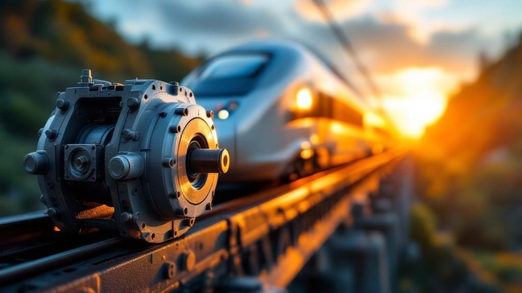
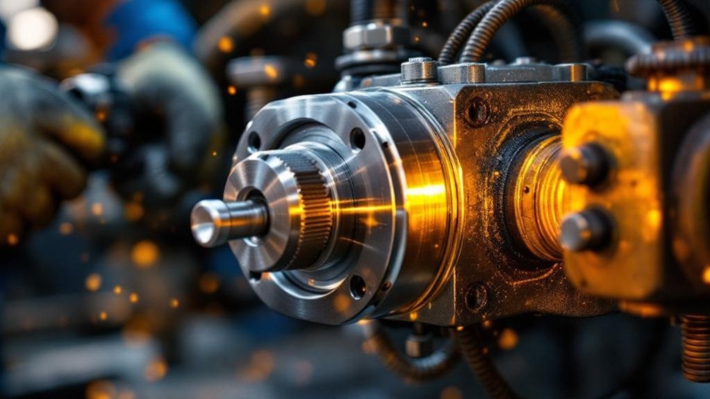
How Do You Detect Internal Seal Leakage Early?

Think of seal leakage as your damper’s silent scream before it goes mute. You catch it early by monitoring the rod for a clinging, wet film that’s more than a whisper. Track performance fade through force-velocity graphs; a sagging curve reveals lost fluid. Regularly inspect the boot for clandestine oil pools. Use thermal imaging to spot a cool zone where damping’s fire dies. These systematic checks let you hear the faintest cry of failure, preventing a total shutdown.

Can Dampers Be Reconditioned After Fluid Contamination?

You can recondition dampers after fluid contamination if you catch the damage early. You’ll first fully disassemble the unit and inspect every internal component. You check for eroded valve seats and scored piston rods. You then replace all seals and flush the contaminated oil completely. You refill it with approved high-viscosity-index fluid. You’ll finally dyno-test it against its original force-velocity curve, ensuring stable damping performance recovers.

How Do Hydraulic Dampers Interact With Air Springs?

Your locomotive’s hydraulic dampers and air springs form an integrated suspension system. Air springs handle static load and primary vertical support, while dampers control dynamic motion. You see this on a heavy-haul EMD SD70ACe, where adjustable dampers precisely manage rebound from air spring compression during curve negotiation. The dampers resist rapid displacement, preventing excessive bounce and pitch. This systematic interaction maintains consistent wheel-rail contact force, optimizing hunting stability across speed ranges without compromising the pneumatic isolation benefits.

What Are the Total Cost Differences Between Reconditioning and Replacement?

You weigh reconditioning’s lower upfront cost against replacement’s longer lifecycle. Reconditioning typically costs 30-50% of a new damper’s price, but you’ll face shorter service intervals and variable quality. Replacement incurs higher initial capital, yet delivers predictable performance, full warranty coverage, and extended maintenance cycles. Your total cost analysis must factor in downtime, labor for changeouts, and reliability risks over the locomotive’s operational life.

The Better Damper Assembly: Proven Way to Secure Rail Ops

The Better Damper Assembly: Proven Way to Secure Rail Ops

Your locomotive’s damper assembly is the hydraulic backbone that converts destructive kinetic energy into heat, directly preventing hunting oscillations and wheel lift that threaten your operations. You maintain consistent wheel-to-rail contact because calibrated piston orifices force fluid through precision passages, suppressing harmonic resonance before it escalates into derailment risk. Properly sized yaw, vertical, and lateral dampers protect your wheelsets, bearings, and bogie structure from fatigue. The right damping curve secures high-speed stability across every route condition.

What is a damper assembly in a locomotive and why is it critical for rail operations?

A locomotive damper assembly is a hydraulic shock absorber. It connects the bogie to the axle boxes. It dissipates energy from track-induced vibrations. This controls unwanted sway and bounce. The damper ensures stable wheel-to-rail contact. It converts kinetic energy into heat. This protects the locomotive structure. It is vital for ride quality.

The assembly uses a piston in a hydraulic cylinder. Fluid passes through precise orifices. This generates damping force. It manages yaw, pitch, and bounce motions. The damper reduces dynamic loads on bogie frames. It extends the life of wheelsets and bearings. Advanced types offer adjustable damping rates. This adapts to speed and load conditions.

Dampers are critical for operational safety. They prevent harmonic resonance and derailment risks. Poor damping causes wheel unloading and traction loss. It accelerates wear on rails and components. Maintenance costs increase without effective dampers. High-speed and heavy-haul services rely on them. Procurement must prioritize quality and reliability. Damper performance directly affects lifecycle costs.

Key Takeaways

  • Hydraulic dampers prevent harmonic resonance that can escalate into derailment at speed.
  • They maintain constant wheel-to-rail contact by suppressing cyclical wheel lift and bounce.
  • Yaw dampers resist hunting oscillations, securing bogie alignment for high-speed stability.
  • Kinetic energy is converted into heat, protecting wheelsets and bogie structures from dynamic loads.
  • Proper damping calibration avoids both instability from undersized units and inefficiency from oversized ones.

Understanding the Locomotive Damper Assembly

Understanding the Locomotive Damper Assembly

You know a locomotive damper assembly as a hydraulic shock absorber linking the bogie to axle boxes. It evolved from simple friction snubbers into precision devices managing yaw, pitch, and bounce motions. Key terms you’ll work with include damping coefficient, orifice, and hysteretic loop.

Definition and Basic Function

locomotive damper assembly is a hydraulic device that manages suspension movement and maintains wheel-to-rail contact. You depend on this hydraulic damping system locomotive component to absorb track-induced shocks. It converts kinetic energy into heat to control sway, bounce, and yaw effectively.

  • You see a sealed piston forcing fluid through calibrated orifices inside the cylinder.
  • Observe the assembly connecting bogie frames to axle boxes for controlled motion.
  • Experience reduced dynamic loads protecting wheelsets, bearings, and the bogie structure.

The locomotive damper assembly dissipates vibration energy instantly. This prevents wheel unloading and ensures traction. Your damping choices directly stabilize the ride and extend component life. You secure operational safety through this proven vibration control.

Historical Evolution

Before hydraulic systems became standard, early locomotives relied on leaf springs and simple friction snubbers to quell oscillations. You’d see engineers demand better rail vehicle vibration control as speeds increased. The 1950s introduced the hydraulic damping system locomotive, a leap from rudimentary designs. This bogie suspension damper used viscous fluid through orifices for consistent energy dissipation. By the 1980s, you’d find these dampers paired with air springs for refined dynamics. Today, you’re sourcing electronically controlled systems that adapt in real-time. These modern bogie suspension dampers adjust rates via external valves for effective rail vehicle vibration control. The progression from friction to smart hydraulics ensures you can match damping precisely to track demands and service weights.

Key Terminology

Grasping the precise language of a locomotive damper assembly lets you specify and maintain these parts properly. Key terms include:

  • Damping coefficient: force per unit velocity; it quantifies damping stiffness.
  • Orifice: precision piston passages that meter oil to generate force.
  • Yaw damper: lateral device that controls bogie rotation, preventing hunting.

You’ll use these specs to align damper response with your locomotive’s weight and speed. Understanding them ensures you avoid undersized dampers that cause instability or oversized ones that waste energy. Correct terminology also streamlines communication with suppliers during overhauls. It helps you diagnose issues like cavitation or seal leakage by referencing exact component names. Mastering this vocabulary cuts procurement lead times and boosts fleet reliability. These three terms build your essential maintenance baseline today.

Components and Working Principle

Components and Working Principle

You’ll find the hydraulic cylinder and piston at the assembly’s heart, forcing oil through valve orifices to generate damping force. You control fluid dynamics via these precision passages, instantly converting vibration energy into heat. You then integrate the damper directly with the bogie suspension to manage yaw, pitch, and bounce motions effectively.

Hydraulic Cylinder and Piston

Every locomotive damper assembly relies on a precision-located piston inside a hydraulic cylinder. You see this core unit transform kinetic energy from bogie movements into heat. The piston rod forces the piston through high-grade hydraulic oil. This action pressurizes fluid within the cylinder’s chambers.

  • You observe a hardened, chromed piston rod sliding through a multi-stage seal pack. This prevents fluid escape under extreme pressure.
  • You find the main piston ring creates a controlled, tight gap against the cylinder’s honed inner wall.
  • You see the hydraulic fluid resisting shear, generating a damping force directly proportional to the piston’s movement speed.

This resistance effectively manages yaw and bounce in your rail vehicle vibration control system. The sealed cylinder protects this process from contaminants. It ensures consistent performance for your bogie suspension damper.

Valve Orifices and Fluid Dynamics

While the piston generates movement, calibrated valve orifices dictate your damper’s precise reaction force. You manage fluid dynamics strategically. Orifice size and geometry control flow resistance. As piston speed increases, fluid shear through these passages generates velocity-dependent damping. You’ll find stacked shim valves or poppet systems covering machined ports. They deflect progressively under pressure, varying the effective orifice area. This prevents harsh lock-up during high-speed impacts. Your damper’s bleed circuit handles slow motions, ensuring compliance. You’re converting kinetic energy to heat reliably. Each orifice set targets specific vibration modes. This systematic metering secures your locomotive’s wheel-to-rail contact and bogie stability.

Integration with Bogie Suspension

As the damper assembly links bogie and axle boxes, it works alongside springs and linkages to control dynamic motion. You see it mounted strategically to form a cohesive suspension system. The damper doesn’t act in isolation; it’s a tuned partner in the bogie’s kinematic chain. Its precise interaction manages three critical actions:

  • You dampen vertical bounce in concert with primary coil springs, preventing resonant amplification.
  • Manage lateral sway by working against the axle box’s lateral stops and linkages.
  • Control bogie yaw rotation through longitudinal damping, guiding stable curving.

This integrated system converts disruptive vibrational energy into heat across the entire assembly. You secure consistent wheel-to-rail contact, directly protecting the locomotive’s structure and ensuring safe, stable operation at speed.

Types of Damper Assemblies in Locomotives

Types of Damper Assemblies in Locomotives

You’ll start with passive hydraulic dampers—the workhorse of most fleets—where fixed orifices provide consistent, reliable force. Then, you’ll consider semi-active and active systems that adjust damping in real time, using controllers and sensors to optimize ride quality. Finally, you’ll match application-specific designs to your locomotive’s duty, whether it’s a high-speed passenger unit or a heavy-haul freight bogie.

Passive Hydraulic Dampers

Passive hydraulic dampers are the simplest and most common type found in freight locomotives. You’ll find they use a fixed-orifice design that forces oil through unchanging passages, generating consistent damping force from track-induced motion.

  • You see a piston displacing hydraulic fluid through calibrated holes, converting kinetic energy into heat directly.
  • Rely on this simple, robust construction which keeps manufacturing and maintenance costs low.
  • You accept its fixed damping curve, as it can’t adapt to varying speeds or loads, making it a compromise for mixed conditions.

Their simplicity delivers proven reliability for heavy-haul cycles. You sacrifice adjustability, but gain a durable, low-maintenance solution where predictable performance is king.

Semi-Active and Active Dampers

Moving beyond fixed-orifice designs, semi-active and active dampers adjust damping force in real time. You’ll see electronically controlled valves quickly alter orifice sizes based on sensor feedback. This tailors resistance to track conditions and speed. You can also deploy magnetorheological (MR) fluid dampers. Here, a magnetic field instantly changes the fluid’s viscosity. That lets you modulate damping without moving parts. The system reads bogie acceleration and sends signals constantly. You gain superior yaw and bounce control, adapting to curves or irregularities instantly. These assemblies reduce wheel unloading more effectively. You’ll maximize stability while maintaining welded rail integrity. The result is dynamic performance conventional dampers can’t match. Your locomotive adjusts its ride control cleverly, not rigidly.

Application-Specific Designs

Engineers tailor locomotive damper assemblies to manage specific motion modes. You’ll find that each type targets a distinct instability for precise rail vehicle vibration control.

  • Yaw dampers counteract lateral bogie rotation, stabilizing high-speed tracking and preventing hunting oscillation.
  • Vertical dampers mount between the bogie and axle boxes to control bounce, absorbing impacts from rail joints or irregularities.
  • Lateral dampers connect the bogie frame to the car body, restricting side-to-side sway and enhancing curve negotiation.

Selecting the correct hydraulic damping system locomotive unit demands matching the bogie suspension damper design to the service profile. This systematic approach secures wheel-to-rail contact and prolongs component life. You ensure operational safety by prioritizing this application-focused integration.

Critical Role in Rail Operations

Critical Role in Rail Operations

You rely on the damper assembly for safety, as it prevents harmonic resonance that can lead to derailment. It also directly shapes ride quality by controlling bounce and sway, which protects your crew and sensitive cargo. Over time, effective damping reduces dynamic stress on bogies and wheelsets, cutting your maintenance costs and extending component life.

Safety and Derailment Prevention

While a damper assembly constantly manages routine vibrations, its most dramatic role is preventing catastrophic derailments. You rely on this hydraulic damping system to suppress dangerous oscillations before they escalate. Specifically, the bogie suspension damper counters harmonic resonance that builds at speed. It stops wheel lift, keeping your locomotive safely on the rails.

  • Resonance Control: The damper dissipates energy that would otherwise amplify body and bogie oscillations, preventing a loss of stability.
  • Wheel Unloading Prevention: It maintains consistent wheel-to-rail force, counteracting the cyclical lift that can precede a flange climb derailment.
  • High-Speed Stability: At velocity, it resists yaw motions that cause hunting, securing the truck’s alignment under your locomotive.

Ride Quality and Passenger Comfort

Beyond the critical safety functions, a locomotive’s damper assembly directly dictates ride quality for passengers and crew. You minimize vertical and lateral vibration transmission from the bogie to the car body. A high-performance hydraulic damping system locomotive suppresses frequencies that cause discomfort and fatigue. Your bogie suspension damper controls pitch and bounce motions, ensuring a smoother journey.

You must adhere to rigorous standards like UIC 513 and ISO 2631, which define vibration exposure limits. Meeting these specifications demands rail vehicle vibration control that maintains consistent performance across speed ranges. You’ll find that precisely tuned damping transforms the in-cab environment, reducing distracting physical oscillations. Ultimately, your investment in superior damper technology pays off through enhanced passenger satisfaction and crew alertness, solidifying your locomotive’s reputation for dependable, comfortable service.

Component Longevity and Maintenance Reduction

A locomotive’s damper assembly consistently shields critical components from destructive fatigue loading. You reduce bogie frame stress and dynamic loads on wheelsets, cutting lifecycle costs. This hydraulic damping system locomotive part directly extends service intervals for bearings and axles.

  • You dissipate vibration energy that otherwise accelerates metal fatigue in bogie frames.
  • Stabilize wheel-to-rail contact, preventing uneven wear on wheelsets and lowering replacement frequency.
  • Protect axle box bearings from impact shocks, slashing unplanned maintenance and associated downtime.

You’ll see fewer overhauls and a direct drop in material expenditures. This systematic approach converts kinetic chaos into controlled heat, keeping your heavy-haul or high-speed locomotive in service longer with proven reliability.

Procurement and Maintenance Considerations

Procurement and Maintenance Considerations

When you select a damper, you must evaluate the damping curve against your specific locomotive’s mass and route conditions. You then analyze lifecycle costs by comparing a unit’s purchase price against its validated mean time between failures. You implement inspection best practices by using dynamometer testing to track performance degradation, not just checking for leaks.

Selection Criteria for Engineers

Engineers must evaluate precise damping force curves to match a locomotive’s mass and service speed. You’ll need specific data from manufacturers, not generic catalog values. This ensures the hydraulic damping system locomotive suppresses primary and secondary suspension movements effectively.

  • Check the bogie suspension damper’s stroke length against maximum axle travel. Insufficient stroke causes bottoming out and catastrophic failure.
  • Verify the operating temperature range for your climate. Fluid viscosity shifts alter damping rates, risking rail vehicle vibration control loss.
  • Confirm mechanical and hydraulic compatibility with existing bogie designs. Mounting pin diameters and seal materials must match exactly.

You should then validate these specs against your route’s tonnage and curvature profile.

Reliability and Lifecycle Cost Analysis

Shifting focus from pure engineering specs, reliability and lifecycle cost analysis transforms how you procure locomotive damper assemblies. You evaluate mean time between overhauls against operational demands, demand warranty terms that cover premature hydraulic damping system locomotive failures. You calculate total cost of ownership, factoring in bogie suspension damper replacements and rail vehicle vibration control downtime. This systematic approach reveals that cheaper units often escalate lifecycle expenses. You prioritize assemblies with proven durability records, ensuring stable wheel-to-rail contact. Your procurement decisions directly reduce long-term maintenance burdens. You secure performance and safety by investing in dampers that minimize lifecycle costs.

Inspection and Overhaul Best Practices

Integrating a rigorous inspection routine into your procurement plan safeguards damper performance. You’ll systematically prevent failures before they compromise bogie suspension damper reliability.

  • Visual and Seal Checks: Inspect the hydraulic damping system locomotive unit for oil misting, rod scoring, or dust boot tears. You’ll spot early seal degradation fast.
  • Fluid Analysis: Sample oil from the rail vehicle vibration control assembly. You’ll detect metal particulates or viscosity breakdown indicating internal wear.
  • Dyno Validation: Test dampers on a dynamometer to map force-velocity curves. You’ll confirm the locomotive damper assembly meets its specified damping rates.

Base your overhaul decision on economics. If a rod is pitted or the cylinder bore is damaged, replace the unit outright to avoid unscheduled downtime.

Frequently Asked Questions

What Environmental Factors Degrade Damper Seals Fastest?

You’ll see your damper seals as a shield wall against the elements. Heat and cold launch the first assault, causing thermal cracking. Ozone and UV follow, slicing into the rubber’s molecular chains. Then dust and grit grind away at the surface like relentless sandpaper. Finally, chemical agents from cleaning solvents or hydraulic fluid leaks swell and soften the material. You must combat these attackers with diligent maintenance and robust materials.

How Do Damper Specs Differ for Mountainous Routes?

You spec dampers with stiffer valving and higher heat tolerance for mountainous routes. You need increased damping force to manage constant, severe pitch and yaw. So, you select larger oil reservoirs to dissipate intense, sustained heat from prolonged braking. You prioritize heavy-duty seals resisting extreme pressure spikes. You may specify semi-active systems to adjust rates on steep grades. This prevents fade and maintains wheel contact through tight curves.

Can Aftermarket Dampers Void Locomotive Warranties?

You risk nullifying your warranty when you install aftermarket dampers that do not meet OEM specifications. Manufacturers stipulate approved components to guarantee performance and safety. Using unverified parts shifts liability, as they can’t vouch for their interaction with the locomotive’s dynamic systems. Always verify your purchasing decisions against the warranty terms before retrofitting. Prioritize OEM or strictly equivalent-approved dampers to maintain coverage and ensure the hydraulic damping system locomotive integrity.

Is Damping Fluid Disposal Regulated by Rail Authorities?

Yes, rail authorities strictly regulate damping fluid disposal. You must follow environmental protocols when handling used hydraulic oil from your locomotive’s damping system. Your workshop collects spent fluid in designated containers for certified recycling or incineration. Never pour it into drains or soil. You work with licensed waste contractors who track disposal from cradle to grave. Your compliance avoids fines and protects the rail corridor. Always maintain disposal records for regulatory audits.

Are Rebuilt Dampers as Reliable as New Units?

You might assume a rebuilt damper cuts corners, but it can match new reliability when you demand a systematic remanufacturing process, ensuring the core components—piston rod, cylinder—undergo rigorous inspection and machining. You’re replacing all seals and valves with OEM-spec parts, not just repainting; you’re verifying performance on a calibrated dynamometer. This blueprint restores the damping curve to factory standards, giving you predictable, safe vibration control at a fraction of the cost.

Translate »