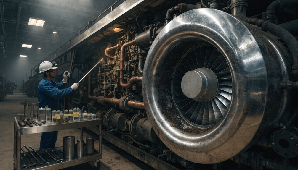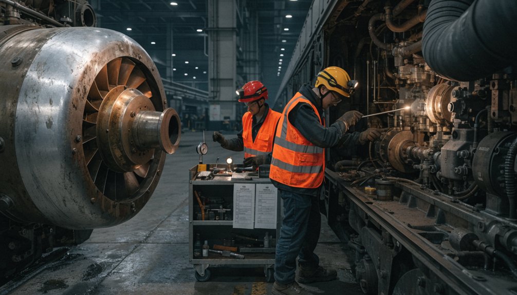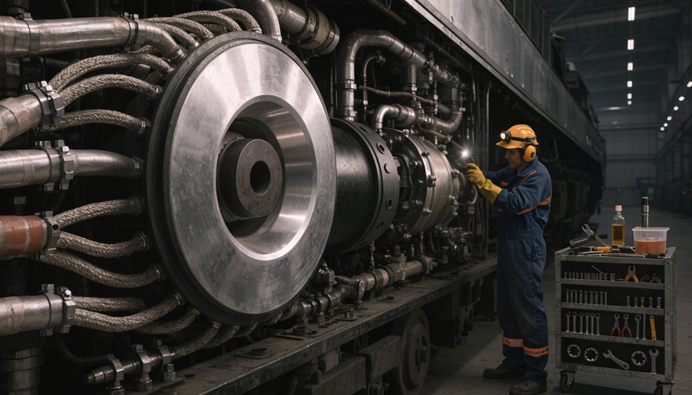
How Our EMD 710 Turbo Torque Procedures Make a Better Seal

How Our EMD 710 Turbo Torque Procedures Make a Better Seal

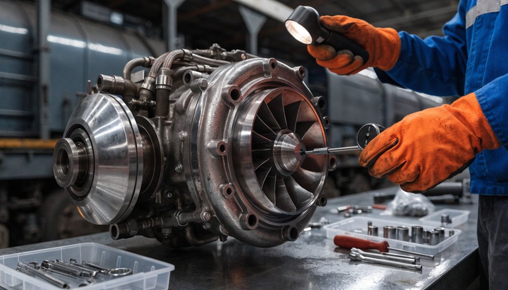
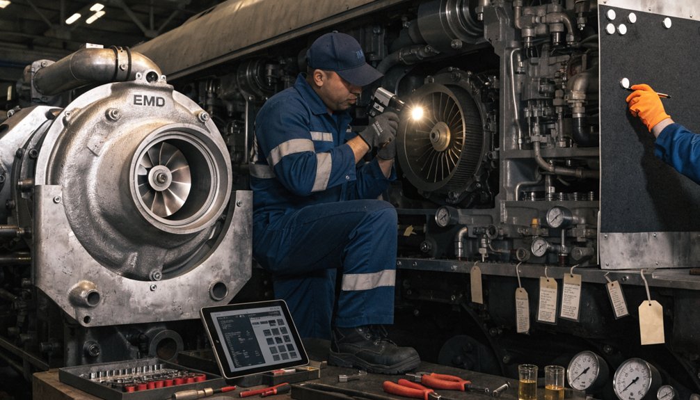
Torque procedures and fastener practices during routine turbo hardware rework on EMD 710 locomotives

You face tight tolerances and critical reliability when reworking turbo hardware on EMD 710 locomotives. Proper torque and fastener care protect power, efficiency, and uptime. This section outlines precise steps, safeguards, and practical tips you can apply in sourcing spare parts from Mikura International. What Torque Values Apply to EMD 710 Turbocharger Mounting Bolts?

Introduction

You face tight tolerances and critical reliability when reworking turbo hardware on EMD 710 locomotives. This guide outlines torque procedures that prevent leaks, misalignment, and gasket failures during routine rework.

Key tasks you will master include defining scope, establishing a robust torque sequence, selecting appropriate lubricants, inspecting fasteners, and performing verification steps. These practices ensure proper seal and fit consistently.

  • Define the scope of turbo hardware rework on EMD 710 engines.
  • Clarify torque sequencing, lubricant use, and fastener inspection requirements.
  • Specify verification steps to ensure proper seal and fit.
  • Provide practical tips to reduce rework and downtime.
  • Highlight safety and reliability considerations for locomotives.

The turbocharger in EMD 710 engines remains a core reliability component. Proper torque control preserves seal integrity and engine performance across V8, V12, and V16 configurations. Misapplied torque can lead to leaks, gasket damage, and accelerated wear in turbo housings and manifolds.

Mikura International provides specialized, supply chain ready parts and technical guidance for turbo hardware rework. We focus on locomotive applications, aligning with industry standards and tight tolerance requirements to minimize downtime.

AspectKey Considerations
ScopeExecutive rework of turbo assemblies on EMD 710 family engines
Torque disciplineSequence, stage torque, verification
Reliability focusSeal integrity, gasket stability, vibration resistance

Related Innovation

Patent · 2025-08-21
US20250264068A1Operating Modes for Two-Cycle Uniflow-Scavenged Diesel EngineMethods of operating a two-cycle uniflow-scavenged engine, especially at lower loads. The exhaust valves of one or more of the engine’s cylinders may undergo exhaust valve deactivation (EVD), that is, a cylinder’s exhaust valve is activated with a frequency that is less frequent than every engine cycle.
View Patent

2. Surface Preparation and Fastener Condition Monitoring

Surface prep and fastener condition are crucial for reliable turbo rework on the EMD 710 diesel engine. Poor cleanliness or damaged bolts can ruin seals and load balance. This section provides focused checks to ensure repeatable torque results without duplicating earlier guidance.

Deck and flange surface cleanliness requirements

Ensure mating surfaces are free of oil, grease, carbon, and debris before reassembly. Contaminants compromise gasket seating and seal performance. Use lint-free wipes and approved solvents.

  • Inspect deck and flange faces for flatness and burrs; address glazing or chatter marks to prevent uneven seating.
  • Remove rust scale with non-abrasive methods to avoid embedding particles into the mating surface.
  • Dry surfaces completely before bolt installation to ensure accurate torque readings.

Fastener inspection criteria (stretch, elongation, corrosion)

Assess fasteners for load-bearing capability prior to reuse. Damaged bolts are a common source of turbo assembly failures.

  • Measure elongation against manufacturer specs; replace if out of tolerance.
  • Inspect threaded portions for cross-threading, galling, or corrosion.
  • Discard bolts with coating damage or significant sidewall wear.

Use of thread lubricants vs dry torque scenarios

Lubrication changes friction and torque readings. Apply lubricant only as specified for the selected torque method and fastener type.

  • Dry torque is used when lubrication is not approved or surfaces are clean and dry.
  • Lubricated torque requires the approved lubricant type and amount; document lubrication for traceability.
  • Establish a consistent lubrication protocol to achieve repeatable results across sessions. Use a calibrated torque wrench and follow the recommended torque patterns when securing liners.

For guidance on approved lubricants and torque sequences specific to EMD 710 turbo hardware, reference Mikura International technical bulletins.

3. Bolt Tightening Sequences and Patterning for Turbo Assemblies

Recommended tightening sequence for turbine housings and manifolds

Apply a cross or spiral pattern to distribute clamping force evenly around the joint.

Begin at the flange center and progress outward in a controlled spiral or star pattern.

Ensure all bolt heads engage to the same seating depth on the flange.

  • Adopt a star or spiral sequence to minimize bowing and distortion.
  • Maintain bolt heads flush with the flange during initial seating.
  • Avoid skipping bolts to ensure uniform compression across the joint.

Stage by stage torque application

Implement three progressive stages to establish a stable seal. Do not skip stages.

  • Initial snug
  • Intermediate
  • Final

Adhere to the sequence in each stage to maintain uniform clamp load across the joint. For the fastener torque sequence and specified values, consult reliable resources.

Torque verification methods and acceptance criteria

Use a calibrated instrument and document every result for traceability.

Inspect for uniform contact across mating surfaces after torquing.

  • Perform angle or torque verification to confirm pattern integrity.
  • Record readings for each bolt and compare to target values.
  • Retorque any bolt showing drift within the acceptance window.

4. Torque Tools, Calibration, and Best Practices

Choose torque tools that deliver repeatable results for EMD 710 turbo hardware. Precise control and traceability minimize rework and leaks.

Preferred torque wrench types for turbo hardware

Select calibrated wrenches suited to the small to mid-range fasteners used on EMD 710 turbo assemblies. Ensure clear verification at setpoints is possible.

  • Digital click wrenches provide direct torque readouts and data capture for records.
  • Click-type wrenches offer tactile confirmation with consistent accuracy across cycles.
  • Angle-enabled wrenches help verify pattern integrity during final stage tightening.

Calibration frequency and traceability

Adhere to a disciplined calibration regime so readings reflect true load. Maintain and reference a traceable calibration history.

  • Calibrate at shift start or after tool replacement to ensure accuracy.
  • Use an accredited lab or in-house standard with a certificate for every calibration event.
  • Log calibration date, next due date, and tool serial number on the tool tag.

Breaker bar use and torque wrench considerations during removal

Breaker bars help manage bolt removal without exceeding tool capability. Use them judiciously to protect threads.

  • Use breaker bars only to loosen and avoid applying torque beyond the tool’s rated capacity.
  • Avoid sudden impacts that can nick threads or bend fasteners during removal.
  • Maintain the established removal sequence to prevent binding and stress concentrations.

5. Fastener Materials, Coatings, and Compatibility

Select fasteners that withstand high temperature, vibration, and exhaust gas exposure. Correct material choice reduces seal failures and loosening risks during turbo rework on EMD 710 engines.

6. Rework Procedures: Step-by-Step Torque Managed Workflow

Disassembly precautions and bolt management

Plan disassembly to preserve bolt order and torque history. Tag assemblies and keep bolts with their components. Inspect threads as components come off.

  • Document bolt position and length before removal.
  • Use organized trays to prevent cross mating of fasteners.
  • Inspect threads for galling or rust, clean as needed.

Reassembly with torque control at each stage

Apply torque in staged increments using the approved sequence. Confirm each stage before moving on. Keep mating faces clean.

  • Start with snug torque to seat components evenly.
  • Proceed to intermediate torque increments per pattern.
  • Finish with final torque value and confirm pattern integrity.

Post reassembly verification and leak and fit checks

Run functional checks and seal verification after torquing. Record readings and look for leaks or misalignment. Address any variance quickly.

  • Run a leak test on all joints within the turbo housing.
  • Check clearances and misalignment with a calibrated gauge.
  • Retorque any bolts showing drift within acceptance.

7. Troubleshooting and Common Pitfalls in Turbo Rework

Symptoms of under or over torquing

Detect issues early to avoid damage. Look for uneven joint gaps and creeping leaks. Monitor torque progression for anomalies and note any stall or slower-than-expected readings during tightening.

  • Under torquing shows gaps at mating faces and early leaks under load.
  • Over torquing causes thread galling and bolt head flattening.
  • Mixed results indicate inconsistent torque readings across identical fasteners.

Impact of improper torque on seal integrity and performance

Torque errors compromise seals and cooling paths, reducing efficiency and increasing hot spot risk in service.

  • Insufficient clamp load allows seal extrusion and leaks under vibration.
  • Excessive load risks bolt failure and turbine interface distortion.
  • Uneven torque degrades gasket seating and fuel air control in the turbo path.

Corrective actions and retorquing protocols

Apply disciplined steps to restore integrity and document results.

  • Retorque according to the approved pattern after a heat cycle or cooldown.
  • Inspect threads and replace damaged fasteners before reassembly.
  • Recheck joint clearances with calibrated gauges and confirm proper seal seating.
  • Record torque values and sequence outcomes for traceability.

FAQ

What torque method is preferred for EMD 710 turbo bolts?

Use a calibrated torque wrench with a linear scale and follow the stage by stage pattern for turbine housings and manifolds. Verify readings against the documented torque sequence after each stage and ensure threads and mating surfaces are clean for accurate measurements.

  • Prefer direct torque measurement over relying on feel alone.
  • Use a torque angle method only if the maintenance plan specifically approves it.
  • Record each stage value for traceability and audits.

How should thread lubricants influence torque readings?

Lubricants reduce friction and can elevate readings if misapplied. Apply only when the specification calls for it. When used, expect lower friction and adjust target values accordingly. Avoid excess lubrication near seals to prevent contamination.

  • Document lubricant type and the application point.
  • Avoid mixing lubricants across different fastener types.
  • Re-check torque after cooldown if seating conditions change due to lubrication.

What are signs that bolt engagement is insufficient or excessive?

Look for abnormal gaps, misalignment, or creeping leaks. Insufficient engagement manifests as uneven joint faces, while excessive engagement can cause thread galling or bolt head deformation. Compare observations to the approved pattern and tolerances.

SignActionNotes
Uneven jointRetorque per patternCheck seating and debris
Visible gallingReplace fastenerInspect thread condition
Leak at jointVerify seating and re-torqueAssess gasket integrity

Conclusion

Key takeaways for safe and reliable turbo hardware rework

You must maintain precise torque control during routine EMD 710 turbo work. Keep fasteners and mating surfaces clean to preserve seals and alignment. Adhere to the documented sequence to minimize distortion and ensure repeatable results.

Use calibrated tools and verify readings after each stage. Plan every step and record results for traceability, audits, and future maintenance.

  • Adopt stage-by-stage torque application for all turbo components.
  • Maintain clean threads and apply lubrication only as specified.
  • Verify joint alignment with calibrated gauges during reassembly.
  • Record all torque values and sequence data for maintenance history.
  • Replace any damaged fasteners before final assembly.

Quality assurances and supplier support from Mikura International

Mikura International provides documented torque guidance and verified fastener kits tailored to EMD 710 turbo systems. Expect traceable lot numbers, validated coatings, and compatible anti-seize formulations. Our guidance emphasizes compatibility and long service life for turbo assemblies.

Assurance AreaWhat Mikura DeliversBenefit
Tool calibrationCertified torque wrenches and periodic calibrationConsistent readings across maintenance cycles
Fastener qualityHigh-grade bolts with compatible coatingsReduced galling and extended life
Technical documentationPatterned torque sequences and acceptance criteriaClear guidance for audits and compliance

References

The Best Ways to Actually Make Your EMD 710 Turbocharger Last

The Best Ways to Actually Make Your EMD 710 Turbocharger Last

You should inspect EMD 710 turbochargers daily, at planned maintenance intervals, and during major overhauls, adjusting frequency for duty cycle and boost trends. Check oil level, feed and drain lines, exhaust connections, soot, smoke, leaks, mounting security, and baseline boost under load. After cooldown, inspect accessible blades and nozzle areas for damage. During heavy-haul inspections, verify bearing condition, rotor movement, and oil pressure. Log defects, boost changes, and corrective actions; the following guidance explains each step.

Key Takeaways

  • Align turbocharger inspections with daily checks, rolling inspections, heavy-haul intervals, and major engine overhauls based on duty cycle and performance trends.
  • Perform daily visual checks for oil leaks, soot streaks, smoke, housing damage, loose connections, and abnormal noise or boost readings.
  • Verify oil level, oil condition, feed and drain flow, crankcase pressure, and temperature to protect turbocharger journal bearings.
  • During heavy-haul inspections, inspect bearings, rotor blades, nozzle rings, compressor wheels, and exhaust connections for wear, damage, rubbing, or restrictions.
  • Record mileage, engine hours, oil analysis, boost trends, smoke behavior, defects, and corrective actions to support fleet reliability and return-to-service decisions.

Follow EMD 710 Turbocharger Inspection Intervals

Follow EMD 710 Turbocharger Inspection Intervals

Follow EMD 710 Turbocharger Inspection Intervals through your fleet maintenance plan to protect locomotive power and reliability. Schedule assessments alongside rolling inspections and major engine overhauls. Prioritize boost stability under representative locomotive loads, and record abnormal readings immediately.

Integrate EMD 710 turbocharger inspections with fleet maintenance to protect power, reliability, and boost stability under load.

Investigate sudden pressure drops because leaks, rotor concerns, or airflow restrictions can reduce performance. Escalate sudden pressure rises because blockages or over-boost conditions can threaten engine components. Maintain inspection documentation to establish reliable turbo wear trends across each locomotive class.

Confirm the specified lubricating oil type, condition, and change interval during planned maintenance windows. Clean oil limits journal-bearing damage and reduces excessive rotor friction. Examine blades and nozzle-related components at defined intervals for chips, bends, or erosion. Damaged components reduce airflow efficiency and can accelerate deterioration.

Build interval planning around operating duty, overhaul schedules, and recorded performance deviations. Apply a disciplined Cool down routine by idling before shutdown. This practice supports service-life targets of five to ten years under normal conditions.

Complete Daily EMD 710 Turbocharger Checks

Complete Daily EMD 710 Turbocharger Checks

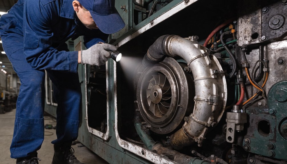
You begin daily EMD 710 turbocharger checks by examining accessible components for leaks, damage, soot streaks, noise, and smoke. Next, verify correct crankcase oil level and condition to protect journal bearings. Finally, inspect exhaust ducting and record boost pressure against established locomotive baselines.

Visual Condition Checks

Daily visual checks of the EMD 710 turbocharger help detect defects before they threaten locomotive availability. You should inspect seal integrity at the bearing housing, scavenge lines, and feed/return connections. Examine housing corrosion, heat discoloration, and staining around nozzle regions. Confirm mounting security, hardware torque indicators, and fastener wear without disturbing secured components.

When safe, observe stack smoke near the turbocharger during operation. Increased black smoke can indicate reduced airflow efficiency or component damage. Record boost pressure trends under load against normal fleet readings. A sudden drop may signal leakage or rotor damage. Conversely, a sudden rise can indicate blockage or over-boost.

After shutdown and cooldown, inspect accessible openings for damaged nozzle-ring areas and chipped, bent, or broken blades. Verify that crews complete the required idle cooldown before shutdown. Don’t touch hot housings or rotating equipment. Document defects immediately for corrective action.

Lubrication System Verification

Before operation, verify clean oil reaches the EMD 710 turbocharger within the prescribed service interval. Confirm oil cleanliness and document any evidence of oil contamination. Dirty oil can quickly damage journal bearings.

Perform a feed line check for secure connections, leaks, restrictions, and adequate inlet flow. Inspect drain flow health at the bearing drain, ensuring oil returns freely without blockage. Compare seepage at feed and drain fittings with previous daily records.

Verify locomotive crankcase oil pressure and temperature remain within approved limits. Use temperature correlation to identify lubrication concerns affecting rotor and bearing operation. Investigate abnormal readings immediately, especially if they accompany changing boost behavior. Isolate the locomotive when lubrication flow is low, blocked, or leaking. Don’t continue operation until qualified personnel correct the condition and confirm proper oil circulation. Record findings, corrective actions, and service-hour status in the daily inspection log.

Exhaust And Boost Inspection

During each heavy-haul inspection, examine the EMD 710 Turbocharger for oil leakage, soot staining, and loose exhaust connections. Review bearing areas, joints, boots, and clamp bands for evidence of exhaust leaks. Confirm clamp integrity before placing the locomotive under load.

Monitor boost stability through typical load changes. Investigate sudden pressure drops, which may indicate leakage, rotor damage, or restrictions. Escalate sudden pressure rises, since blockage or over-boost can threaten turbocharger components.

Inspect turbo shrouds, insulation, and external hardware for cracks or looseness. Examine accessible compressor blades for chips, bends, or imbalance risks. Use thermal imaging after operation to identify abnormal heat patterns. Ensure necessary idle cool-down occurs before shutdown. Verify oil-system service remains current and compliant. Clean, specified oil protects bearings; changing boost readings can help reveal early bearing wear.

Identify Leaks, Vibration, and Damage

Identify Leaks, Vibration, and Damage

Why does early damage detection matter for EMD 710 Turbochargers? You prevent in-service failuresprotect locomotive availability, and reduce safety exposureIsolate the unitfollow lockout procedures, and inspect only after temperatures fall.

  • Check oil feed, return, journal-bearing, and seal surfaces for residue or oil misting.
  • Use Thermal imaging to identify overheating, discoloration, coking, and localized hot spots.
  • Verify boost pressure under load; investigate abrupt drops, rises, or unstable readings promptly.
  • Listen for new harmonics, roughness, or frame-transmitted shaking that indicates alignment wear.
  • Examine compressor and nozzle-ring areas for soot, cracks, impacts, chipped blades, and compromised seal integrity.

Record findings with location, severity, and operating conditions. Compare vibration observations against prior locomotive records. Confirm correct idle-before-shutdown practices, because heat soak accelerates surface damage. Review coolant condition near associated cooling circuits for contamination or abnormal loss. Don’t return the locomotive to service when leaks, vibration, or structural damage remains unresolved. Escalate defects through your maintenance process and obtain qualified technical assessment before release.

Inspect Bearings, Wheels, and Oil Systems

Inspect Bearings, Wheels, and Oil Systems

At every heavy-hold interval, inspect EMD 710 Turbochargers for bearing wear, wheel damage, and oil-system defects. Isolate the locomotive, follow lockout procedures, and allow components to cool before inspection. Check journal bearings for abnormal end-play, shaft movement, heat discoloration, and bearing scoring. Examine lubricant samples for oil contamination that can accelerate wear and reduce film strength.

Inspect the compressor wheel and turbine rotor for nicks, bent blades, erosion, or contact marks. Rotate the assembly carefully and confirm it turns smoothly without rubbing. During load testing, compare boost pressure with the established baseline. A sudden pressure drop may indicate rotor damage or a turbo leak. Conversely, an unexpected rise can signal restriction or over-boost conditions.

Verify correct oil type, service intervals, and cleanliness requirements. Inspect oil feed and return lines, fittings, and cooler operation for restrictions or leakage. Ensure unobstructed lubrication flow, since stable oil supply protects bearings and supports reliable rotor operation under heavy-haul duty.

Record Findings and Schedule Repairs

Record Findings and Schedule Repairs

For each scheduled interval, record EMD 710 Turbochargers data in a dedicated inspection log. Capture mileage, engine hours, oil-analysis results, and boost readings. Compare entries to support trend forecasting and prevent unsafe in-service failures.

  • Flag sudden boost drops for leaks, rotor damage, or airflow restrictions.
  • Document over-boost events, blockage indicators, and black-exhaust observations immediately.
  • Record blade, diffuser, nozzle ring, and journal-bearing conditions after disassembly.
  • Use Nonconformance logging to assign corrective actions, priorities, and technician signoff.
  • Maintain parts traceability for replacements and schedule next inspections from verified results.

Coordinate turbo teardowns with oil-system corrections and injector checks. This approach reduces repeat labor and improves downtime tracking across locomotive maintenance windows. Before returning the locomotive to service, record after-repair boost stability, smoke behavior, and loaded running response. Compare these readings with baseline values. If measurements remain outside limits, hold the unit for further diagnosis. You’ll make repair-versus-deferral decisions using documented wear, fleet history, and operating risk. Schedule work only after confirming clear airflow paths and safe component condition.

Frequently Asked Questions

What Spare EMD 710 Turbocharger Parts Should Heavy-Haul Fleets Stock?

Stock Gasket Seal Kits, Bearing Core Stock, Compressor Seal Sets, and Actuator Spares Inventory for each EMD 710 turbocharger model. Use Install Kit Planning to match fleet quantities, overhaul schedules, and route exposure. Keep turbine-side hardware, oil-line seals, fasteners, and approved replacement sensors available. You’ll reduce locomotive downtime by verifying part numbers, storage conditions, and traceability before release. Don’t substitute unapproved components during field repairs.

How Does Ambient Temperature Affect EMD 710 Turbocharger Inspection Planning?

Ambient variability acts like a hidden furnace, changing how you plan EMD 710 turbocharger inspections. You should shorten inspection scheduling during extreme heat or cold. Monitor intake temperature trends, bearing condition, oil quality, and compressor clearances. High temperatures increase thermal stress and accelerate lubricant degradation. Cold conditions can restrict oil flow and raise seasonal risk. You’ll protect heavy-haul availability by documenting temperature exposure and triggering condition-based inspections before damage escalates.

Which Technician Qualifications Are Required for Turbocharger Overhaul Work?

You need certified training on EMD 710 turbocharger systems and documented overhaul credentials. You should demonstrate diagnostic aptitude for vibration, boost, and bearing-condition assessment. Technicians must possess balancing experience with rotating assemblies and approved balancing equipment. You must follow safety compliance procedures for lockout, lifting, contamination control, and high-speed component handling. Verify practical competency through supervised overhauls, inspection records, and recurrent qualification reviews. Mikura International supports qualified locomotive maintenance programs.

When Should Fleets Replace a Turbocharger Instead of Rebuilding It?

Replace the turbocharger when it becomes a ticking time bomb for locomotive reliability. You should base the Overhaul Decision on severe Inspection Findings, including cracked housings, damaged wheels, or bearing seizure. Compare rebuild costs against replacement using a documented Cost Comparison. Use Performance Monitoring to confirm recurring boost loss, vibration, or oil consumption. Track Failure Mode Trends across your fleet. Don’t rebuild units that can’t meet OEM dimensional limits or safety requirements.

How Can Oil Analysis Support EMD 710 Turbocharger Reliability?

You can improve EMD 710 turbocharger reliability through scheduled oil sampling and laboratory review. Track oil condition, lubricant chemistry, and coolant contamination to identify degradation before bearing damage occurs. Use wear particle analysis to detect abnormal metal generation from rotating components. Compare Vibration trends with oil results to confirm developing faults. You’ll then schedule corrective maintenance, control failure risk, and protect locomotive availability during heavy-haul service.

Translate »