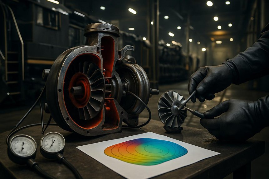
How the EMD 710 Turbocharger Maps Improve Duty Performance

How the EMD 710 Turbocharger Maps Improve Duty Performance

You use EMD 710 compressor and turbine maps to track corrected airflow, pressure ratio, shaft speed, surge margin, exhaust energy, backpressure, and temperature across real notch cycles. The compressor map shows whether boost stays stable during idle recovery, switching, notch-up, and full load. The turbine map shows whether exhaust flow drives boost efficiently without excess heat or scavenging restriction. Together, they (EMD 710 Turbocharger Maps) predict smoke, fuel burn, thermal stress, response lag, reliability, and lifecycle cost across each duty-cycle condition ahead.

How do turbine and compressor maps for the EMD 710 turbocharger influence locomotive duty-cycle performance?

The turbine and compressor maps of the EMD 710 turbocharger determine how effectively the engine breathes across idle, notch changes, and sustained load. In locomotive service, they shape boost, exhaust energy recovery, and transient response, which directly affect tractive effort, fuel use, smoke, and thermal limits.

For rail engineers, the key is matching the turbocharger operating point to the locomotive duty cycle. A compressor map shows where the turbo can deliver stable airflow without surge or excessive discharge temperature. A turbine map shows whether exhaust energy can drive the compressor efficiently at low and high engine loads. Together, they define how well the EMD 710 responds during acceleration, switching, and long-haul running.

For procurement specialists, these maps matter because they influence reliability, maintenance intervals, and life-cycle cost. A poorly matched turbocharger can increase overfueling, lag, fouling, and heat stress in locomotive service. A well-matched unit supports cleaner combustion, better fuel economy, and more consistent performance across changing grades and ambient conditions.

Key Takeaways

  • EMD 710 turbocharger maps verify airflow, pressure ratio, and surge margin across idle, notch changes, and full-load operation.
  • Compressor maps show whether boost and air mass flow remain stable during low-flow events, switching, and rapid throttle commands.
  • Turbine maps reveal how exhaust energy, backpressure, and efficiency affect scavenging, smoke control, and thermal loading.
  • Poor turbine-compressor matching causes boost lag, rich running, higher exhaust temperatures, fuel penalty, and uneven tractive effort.
  • Map-based duty-cycle analysis supports procurement, maintenance intervals, cleaning schedules, reliability planning, and total lifecycle cost control.

EMD 710 Turbocharging in Locomotives
EMD 710 Turbocharging in Locomotives | EMD 710 Turbocharger Maps

You use EMD 710 turbocharger maps to verify airflow, pressure ratio, and surge margin across each locomotive notch. As load changes, you’re asking the turbocharger to match boost demand faster than steady-state test data suggests. Rail duty cycles stress the match harder because grades, throttle transitions, and thermal limits shift engine breathing continuously.

EMD 710 turbocharger maps and engine breathing

The EMD 710’s two-stroke cycle depends on controlled scavenging air at every locomotive load band. You use emd 710 turbocharger maps to verify that airflow supports cylinder clearing, charge density, and combustion stability. Because the engine fires every revolution, weak boost quickly raises smoke, exhaust temperature, and fuel penalty.

Load bandAirflow needMap concern
Idle/low loadStable scavengingSurge margin
Mid loadClean combustionPressure ratio
High loadThermal controlCompressor flow

You should read each operating point against compressor flow and turbine energy lines. That comparison shows whether the turbocharger can move enough air without overspeed, surge, or high discharge temperature. In locomotive service, this breathing margin protects liners, valves, and aftercooler performance under sustained duty.

Locomotive notch changes and boost demand

After confirming engine breathing marginsnotch response shows how quickly the EMD 710 converts fuel demand into stable boost. You see this during rapid throttle changes, when rack position increases before airflow fully catches up. Exhaust energy rises, turbine speed accelerates, and compressor flow must move rightward without crossing unstable regions.

You evaluate EMD 710 turbocharger maps by tracking pressure ratio, corrected flow, and speed during each notch step. A strong match preserves compressor surge margin while building boost fast enough to limit smoke and exhaust temperature. If the turbine efficiency map shows weak energy conversion at that point, boost lags and combustion runs rich. That lag affects tractive effort, fuel rate, and thermal loading. For procurement, you need map evidence that the turbocharger handles notch transients, not just rated load.

Why rail duty cycles are harder than steady-state testing

While steady-state tests hold speed and load nearly constant, rail service forces the EMD 710 through sharper operating changes. You see this when switching demands rapid notch cycling, climbing sustains high exhaust energy, and cruising holds moderate airflow for hours. Bench data can miss these transitions because it averages boost, temperature, and shaft-speed behavior.

In service, you’re managing moving operating points across compressor and turbine maps. A turbine efficiency map helps you judge whether exhaust energy supports boost during acceleration without excess backpressure at load. If matching is weak, you’ll see slower notch response, higher smoke, hotter components, and reduced locomotive duty cycle performance. That’s why EMD 710 turbocharger maps must be reviewed against real routes, tonnage, grades, ambient conditions, and maintenance condition, not only rated-point test results.

Compressor Map and Locomotive Airflow
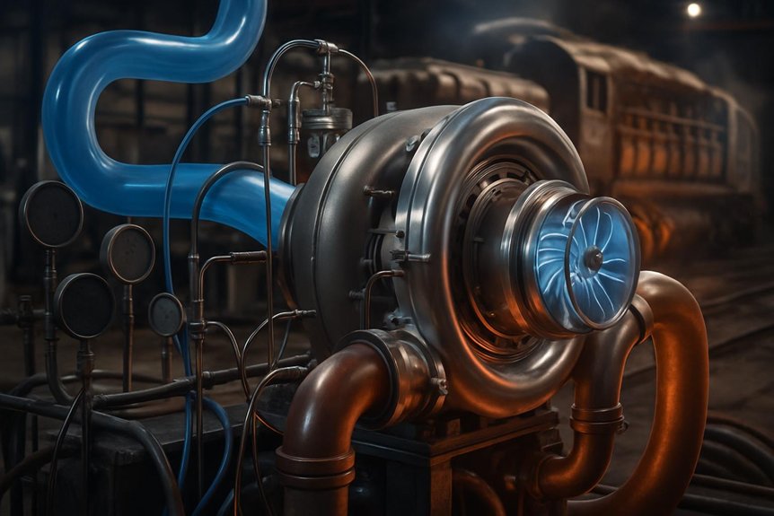
Compressor Map and Locomotive Airflow

You use the compressor map to verify stable airflow across idle, notch changes, and full-load EMD 710 operation. You’ll protect compressor surge margin by checking low-speed response against required boost and air mass flow. You also track discharge temperature because hotter air reduces combustion quality, raises smoke risk, and stresses engine components.

Compressor operating range in locomotive service

Because locomotive loading changes constantly, the compressor map must show a stable airflow zone across idle, notch changeovers, and full-load operation. You use this zone to verify that airflow, pressure ratio, and compressor speed remain aligned with the EMD 710 engine’s fuel demand. That alignment protects locomotive duty cycle performance by supporting clean combustion during switching, climbing, and sustained haul service.

You should read the operating range as a practical envelope, not a laboratory curve. Each point shows whether the turbocharger can supply enough mass flow without pushing discharge temperature or shaft speed beyond acceptable limits. In railroad service, ambient temperature, altitude, filter restriction, and worn components shift those points. Map review helps you predict boost consistency, thermal loading, and maintenance exposure before sourcing or approving replacement hardware.

Surge margin and low-speed response

After defining the compressor operating envelopesurge margin shows how safely the turbocharger handles low-flow locomotive events. In EMD 710 turbocharger maps, you track this margin between the operating line and surge boundary.

During idle recovery, switching, or notch-up commands, airflow can drop while pressure ratio rises. If matching is poor, you push the compressor toward unstable flow. Surge then creates pulsation, boost fluctuation, and slower cylinder air delivery. That response can delay load pickup and stress bearings, seals, and blades.

You should compare expected duty-cycle points against the compressor surge margin, not just rated-load airflow. A wider margin improves low-speed response during transient rail service. However, excessive margin without efficiency can sacrifice useful boost. Mikura International helps you evaluate map data against actual locomotive duty cycle performance.

Discharge temperature and combustion quality

How does compressor efficiency translate into cleaner combustion on an EMD 710 locomotive? You read EMD 710 turbocharger maps to see where airflow stays efficient, dense, and stable under load.

Higher compressor efficiency reduces discharge temperature for a given pressure ratio. Cooler charge air increases oxygen density entering the cylinders. That helps you match injected fuel with available air during notch changes and sustained pulls.

When discharge temperature rises, air density falls and combustion margin tightens. You’ll see more smoke risk, higher exhaust temperature, and slower recovery after load shifts. Fouling or poor map matching pushes the operating point toward hotter regions.

Use compressor map data to compare airflow, pressure ratio, and efficiency islands against your locomotive duty cycle performance. Better alignment supports smoke control, fuel economy, and predictable thermal loading.

Turbine Map and Exhaust Energy Recovery
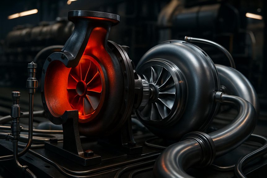
Turbine Map and Exhaust Energy Recovery

You use the turbine efficiency map to track how changing exhaust flow drives boost across each locomotive notch. In two-stroke EMD 710 service, you can’t ignore backpressure because it affects scavenging, cylinder clearing, and smoke control. At high load, you need efficient exhaust energy recovery to limit thermal stress and protect duty-cycle reliability.

Turbine map behavior under changing exhaust flow

As exhaust mass flow and temperature rise across the locomotive load range, the turbine map shows how effectively the turbocharger converts that energy into compressor drive. You use EMD 710 turbocharger maps to verify speed, flow, and efficiency alignment during duty changes.

Duty pointExhaust energyTurbine response
IdleLow flow, low heatLimited drive, low boost
Notch-upRising pulse energyAccelerates rotor quickly
TransitoryUnsteady flowTracks stable efficiency island
Full loadHigh flow, high heatDelivers rated compressor power

At idle, you expect modest recovery, not high boost. During notch transitions, you need rapid energy capture without overspeed. At full load, the turbine efficiency map confirms sustained power conversion, supporting locomotive duty cycle performance.

Backpressure and scavenging in two-stroke locomotives

Turbine efficiency also affects exhaust backpressure, which directly shapes scavenging in two-stroke EMD 710 locomotives. You need enough pressure drop across the cylinders to clear residual gas before fresh charge enters. If the turbine map restricts flow, backpressure rises, trapped exhaust increases, and oxygen availability falls. That reduces combustion quality during notch changes and sustained pulling.

You evaluate EMD 710 turbocharger maps to confirm the turbine can pass exhaust mass flow without upsetting air balance. Lower restriction supports cleaner cylinder clearing, steadier blower-assisted airflow, and stronger compressor work. Excessive backpressure can also distort port scavenging, raising smoke risk and fuel penalty. When turbine matching aligns with the duty cycle, you protect locomotive duty cycle performance through stable breathing, consistent boost, and measured exhaust energy recovery across operating notches.

High-load efficiency and thermal stress control

Control high-load heat by reading the turbine efficiency map against exhaust mass flow and pressure ratio. You can see where exhaust energy converts into shaft power without excessive backpressure. In EMD 710 turbocharger maps, that high-efficiency island matters during notch 8, long grades, and hot ambient operation.

Efficient turbine operation lowers exhaust manifold temperature, turbine inlet temperature, and cylinder thermal loading. It also helps the compressor maintain target boost with less waste energy. When the operating point moves outside the efficient zone, you’ll see higher heat rejection, slower boost recovery, and greater stress on blades, bearings, seals, and aftercoolers. That stress shortens overhaul intervals.

Use measured exhaust temperature, boost, and fuel rate to validate map matching. Data helps you protect reliability while sustaining locomotive duty cycle performance under maximum load.

Duty-Cycle Effects on Performance
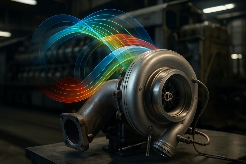
Duty-Cycle Effects on Performance

You see locomotive duty cycle performance change as acceleration, switching, and haulage move the turbocharger across its maps. and track fuel rate, boost, and smoke response to confirm the EMD 710 turbocharger maps match real notch demand. You reduce reliability risk when compressor surge margin and turbine efficiency map data reflect actual railroad conditions.

Acceleration, switching, and haulage scenarios

When a locomotive moves from idle to higher notches, the turbocharger must build boost before fueling exceeds available air. You read EMD 710 turbocharger maps to predict that delay. In switching, short bursts push operating points rapidly across the compressor map. Weak compressor surge margin can make crews feel hesitation, vibration, or uneven loading.

ScenarioOperational feeling
Yard switchingTense, repeated boost recovery
Notch accelerationUrgent airflow demand
Grade entryHeavy thermal rise
Sustained haulageSteady, confident pull

During long sustained pulls, you hold the turbo near a stable island on the turbine efficiency map. Exhaust energy stays consistent, so boost stabilizes and cylinder balance improves. Compare both cases before approval: transient duty exposes response limits, while haulage reveals endurance limits.

Fuel economy and smoke response

After response and endurance limits, fuel burn and smoke show whether the air path truly matches the duty cycle. With EMD 710 turbocharger maps, you compare commanded fuel, boost pressure, airflow, and exhaust temperature at each notch.

Better map matching keeps the compressor operating in efficient islands, so you get denser charge air without excess discharge heat. That improves air-fuel ratio control during acceleration, switching, and sustained haulage. When airflow arrives late, fuel burns rich, cylinders see incomplete combustion, and visible exhaust rises. When the turbine efficiency map matches exhaust energy, you recover more drive power for boost instead of wasting heat. You’ll see lower specific fuel consumption, cleaner stack opacity, and steadier locomotive duty cycle performance across grades, ambient changes, and throttle transitions while preserving available tractive effort.

Reliability under real railroad conditions

Often, real railroad reliability depends on how well the map fit handles contaminated airheat, and rapid notch changes. You see this in EMD 710 turbocharger maps when operating points stay away from surge and overspeed limits.

  1. Fouling: You reduce efficiency loss when compressor flow capacity tolerates dirty filters and airborne dust.
  2. Heat: You protect pistons, valves, and aftercoolers when the turbine efficiency map controls exhaust temperature.
  3. Bearings: You lower thrust load when pressure ratio changes smoothly during notch shifts, not abruptly.
  4. Service life: You extend overhaul intervals when boost, shaft speed, and exhaust energy align with the locomotive duty cycle performance profile.

You can’t remove railroad variability. You can specify map-matched turbochargers that absorb it with stronger compressor surge margin and lower mechanical stress.

Selection and Procurement Considerations
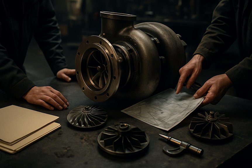
Selection and Procurement Considerations

You should match EMD 710 turbocharger maps to each locomotive mission profile, including switching, grade haul, and sustained notch operation. You’ll need to verify compressor surge margin, turbine efficiency map data, material specifications, and test records before approval. This approach links procurement decisions to maintenance planning, reliability targets, and measurable life-cycle value.

Matching turbo maps to locomotive mission profiles

Match EMD 710 turbocharger maps to the locomotive’s actual mission profile before approving a replacement unit. You’ll reduce mismatch risk when map data reflects real throttle time, load factor, altitude, and ambient temperature.

  1. For yard duty, prioritize compressor surge margin at low airflow and rapid notch changes.
  2. For regional service, balance transient boost response with mid-load fuel efficiency.
  3. For mainline haulage, emphasize stable high-load operation on the turbine efficiency map.
  4. For mixed fleets, compare operating points against recorded duty-cycle histograms before selection.

This approach helps you predict locomotive duty cycle performance with fewer assumptions. You can identify where boost lag, overfueling, exhaust temperature, or fouling may appear. Mikura International supports sourcing decisions with practical application review, not guesswork, for demanding EMD 710 locomotive service conditions.

Specification checks for buyers and engineers

Before approving an EMD 710 replacement turbocharger, procurement teams should request map-based performance data, not only part numbers. You should ask for EMD 710 turbocharger maps showing corrected airflow, pressure ratio, shaft speed, and efficiency islands across expected locomotive notches.

Review compressor surge margin at low-load shifts and high-altitude operation. Check turbine efficiency map data against exhaust temperature, mass flow, and backpressure limits. Require evidence of boost response during notch changes, including acceleration time and smoke-related airflow shortfall. Compare heat rejection, overspeed margin, and discharge temperature with your engine limits. Ask Mikura International for dimensional checks, material specifications, balancing records, and test-stand results. Document acceptable tolerances before purchase, so you can verify performance, not assume interchangeability across demanding rail duty cycles.

Maintenance planning and life-cycle value

When maintenance teams use map data during selection, they can forecast wear risk before it becomes downtime. You use EMD 710 turbocharger maps to link operating points with heat, speed, surge exposure, and fouling sensitivity across locomotive duty cycles.

  1. Compare compressor surge margin against notch transitions, not only rated load.
  2. Check the turbine efficiency map for exhaust energy use during sustained grades.
  3. Track predicted discharge temperature to plan cleaning, inspection, and bearing intervals.
  4. Align replacement specifications with fleet routes, ambient conditions, and load factors.

This approach helps you reduce unplanned removals, smoke events, and fuel penalties. It also supports stronger budget control because you’re buying expected service life, not just hardware. Mikura International helps you evaluate map fit, failure risk, and total ownership cost before procurement.

Frequently Asked Questions

How Does Altitude Affect EMD 710 Turbocharger Map Matching?

Altitude lowers air density, so you push the compressor operating point toward higher pressure ratio and reduced mass flow. That can shrink compressor surge margin, raise discharge temperature, and slow notch response. You’ll also see changed turbine drive because exhaust energy must work harder to maintain boost. When you evaluate EMD 710 turbocharger maps, compare expected route altitude, ambient temperature, load profile, and allowable thermal limits before you source or approve replacements.

Can Fouled Aftercoolers Shift Compressor Operating Points?

Yes, fouled aftercoolers can shift compressor operating points. You’ll see higher charge-air temperature, greater pressure drop, and reduced air density. That forces the EMD 710 turbocharger to work farther right on its compressor map for the same cylinder air demand. You can lose compressor surge margin, raise exhaust temperature, and increase smoke during notch changes. You should inspect pressure differential, outlet temperature, and fouling trends before blaming turbocharger performance alone.

How Often Should Turbocharger Performance Data Be Reviewed?

Like reading smoke signals from the stack, you should review turbocharger performance data monthly, and after major load complaints, overhauls, or aftercooler cleaning. Track boost pressure, exhaust temperature, airbox pressure, turbo speed, and fuel rate by notch. You’ll catch drift before it becomes surge, overfueling, or bearing distress. For EMD 710 turbocharger maps, compare field points against expected compressor surge margin and turbine efficiency trends during scheduled reliability reviews.

Do Seasonal Temperatures Change Surge Risk in Locomotives?

Yes, seasonal temperatures change surge risk in locomotives. You see higher risk in cold dense air if fueling and boost control don’t stay matched. Hot weather can reduce air density, raise exhaust temperatures, and narrow operating margins under load. You should compare EMD 710 turbocharger maps against ambient data, notch profile, and compressor surge margin. That helps you predict unstable airflow, smoke, and thermal stress before reliability suffers.

Can Map Data Help Predict Turbocharger Overhaul Timing?

Yes, you can use map data to flag overhaul timing trends. You compare actual boost, exhaust temperature, shaft speed, and airflow against EMD 710 turbocharger maps. If operating points drift toward lower compressor efficiency, reduced surge margin, or poorer turbine efficiency, you’re seeing fouling, erosion, leakage, or bearing wear. That evidence helps you plan overhaul before smoke, fuel penalty, high thermal stress, or unscheduled locomotive downtime appears.
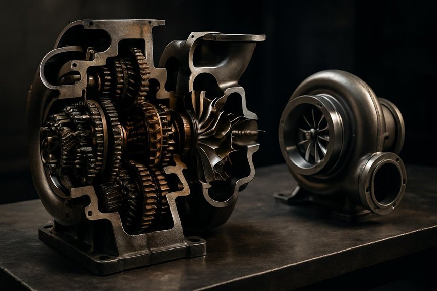

How the EMD 710 Locomotive Turbocharger Makes Better Power

How the EMD 710 Locomotive Turbocharger Makes Better Power

You can view the EMD 710 locomotive turbocharger as a hybrid scavenging air system. At start, idle, and low notches, engine gearing drives the compressor so the two-stroke cylinders get reliable air before exhaust energy builds. As load rises, the turbine accelerates, the centrifugal clutch unloads the gear drive, and the unit acts like a free turbocharger. Unlike exhaust-only turbos, it improves low-RPM response while preserving high-load efficiency, with more to compare in the details ahead.

How does the EMD 710 locomotive turbocharger’s hybrid drive (gear-assisted at low RPM, free-turbine at high RPM) work compared to conventional locomotive turbochargers?

The EMD 710 locomotive turbocharger’s hybrid drive combines a gear‑driven blower and free turbine in one unit. At low engine speeds, a gear train mechanically drives the compressor, ensuring sufficient scavenging air for the two‑stroke diesel. As exhaust energy rises with load, a centrifugal clutch lets the turbine overrun the gear drive, transitioning the unit to pure turbocharger mode.

This hybrid concept differs from conventional turbochargers that rely only on exhaust energy across the speed range. Traditional turbo systems on medium‑speed locomotive diesels can suffer from low‑RPM boost lag and poorer low‑notch response. The EMD design delivers more immediate air delivery at low notches, while still capturing exhaust energy efficiently at higher throttle settings.

For rail engineers and procurement specialists, this brings tangible benefits in throttle response, fuel economy, and emissions. The design also influences maintenance practices, spare‑parts strategy, and lifecycle costing for 710‑powered locomotive fleets.

Key Takeaways

  • The EMD 710 two-stroke needs continuous pressurized scavenging air during cranking, idle, load changes, and all throttle notches.
  • At low RPM, the turbocharger is gear-driven, making the compressor act like a mechanically assisted blower.
  • As exhaust energy rises, a centrifugal clutch allows the turbine to overrun and transition toward free-turbine operation.
  • At high load, exhaust energy drives the turbo efficiently, reducing mechanical load on the engine gear train.
  • Conventional locomotive turbos rely only on exhaust energy, so low-load boost response is generally weaker than the EMD hybrid system.

Understanding the EMD 710 Engine and Its Turbo Needs

Understanding the EMD 710 Engine and Its Turbo Needs | EMD 710 Locomotive Turbocharger

You start with the EMD 710 locomotive turbocharger because the 710 two-stroke engine needs pressurized air for scavenging. You can’t rely on piston motion alone to clear exhaust and fill cylinders efficiently. EMD’s path from Roots blowers to hybrid turbochargers solved low-speed airflow limits while improving high-load energy recovery.

Two‑Stroke Design of the EMD 710 Locomotive Engine

The EMD 710 two-stroke locomotive engine fires every piston on each crankshaft revolution, so it depends on continuous pressurized air. You’re managing a high-output engine with large displacement per cylinder, not a naturally breathing machine. Each power stroke needs fresh air to enter fast, clear residual exhaust, and support stable combustion.

Because the 710 uses ports and exhaust valves, airflow must arrive with enough pressure and volume at all times. You need that air during cranking, idle, changeover, and every throttle notch. If pressure drops, scavenging weakens, temperatures rise, and combustion quality suffers.

That’s why the emd 710 locomotive turbocharger isn’t just a power adder. It’s part of the engine’s basic breathing system, supporting reliable starts, clean idle, and load response.

Why Locomotive Diesels Depend on Turbocharging for Scavenging

On the 710, scavenging links directly to turbocharger performance. You use intake air to sweep exhaust gases from each cylinder, then refill it with clean charge air. The EMD 710 locomotive turbocharger supplies that air under pressure, so combustion stays stable across load changes.

Scavenging stageWhat air doesWhy it matters
Port openingEnters cylinder fastPushes exhaust out
Cylinder clearingReduces residual gasesProtects combustion quality
Fresh refillBuilds oxygen chargeSupports rated horsepower

Without forced induction, you can’t clear cylinders effectively. Power falls, exhaust temperatures rise, and emissions drift out of control. The emd hybrid turbocharger drive matters because your two-stroke locomotive engine depends on positive airflow, not natural aspiration, to breathe correctly.

From Roots Blowers to Hybrid Turbochargers in EMD Locomotives

As EMD locomotive horsepower increased, simple Roots blowers couldn’t recover enough exhaust energy for efficient operation. You still needed positive scavenging air for the two-stroke cycle, but higher loads demanded better fuel use and thermal efficiency. On earlier EMD 645 engines, turbo-superchargers began bridging that gap by combining mechanical assistance with exhaust-driven boost.

With the 710 platform, you see that concept refined into a hybrid drive. The EMD 710 locomotive turbocharger acts like a blower at low speed, then behaves like a free turbine as exhaust energy rises. This gear‑assisted turbocharger in locomotives gives you dependable low-notch air delivery without sacrificing high-load efficiency. For aging fleets, it offers practical balance: reliable scavenging, improved response, and better energy recovery than a Roots-only arrangement.

Inside the EMD 710 Locomotive Turbocharger Hybrid Drive

Inside the EMD 710 Locomotive Turbocharger Hybrid Drive

You’ll see the EMD 710 locomotive turbocharger center on four critical elements: turbine, compressor, gear train, and clutch. At low RPM and low notches, the gear train drives the compressor to support scavenging air. At higher RPM and notches, the clutch lets exhaust energy take over in free-turbine operation.

Key Components: Turbine, Compressor, Gear Train, and Clutch

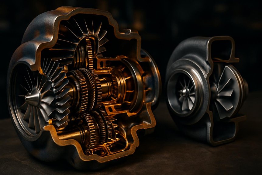
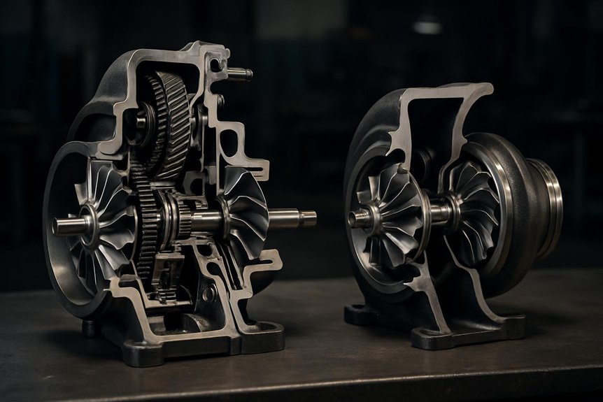
Although the assembly looks compact from the outside, the EMD 710 locomotive turbocharger integrates several critical functions in one housing. You’re looking at a turbine wheel, compressor wheelgear train, and clutch arranged to support two-stroke scavenging demands.

Exhaust gas drives the turbine side, while the compressor side delivers pressurized air into the engine’s airbox. Between them, the internal gearing connects the turbocharger shaft to the engine gear system. That mechanical link makes the EMD hybrid turbocharger drive different from conventional exhaust-only designs.

You also need to account for the overrunning, centrifugal clutch. It lets the turbine overrun and decouple the gear drive as exhaust energy increases. This clutch action enables free‑turbine turbocharger operation without forcing the gear train to carry unnecessary load.

Gear‑Assisted Operation at Low RPM and Low Notches

The gear train and clutch matter most when exhaust energy is still low. During starting, idle, and low notches, the EMD 710 locomotive turbocharger can’t depend on turbine power alone. You need positive air delivery before combustion produces strong exhaust flow.

In this range, the crankshaft drives the turbocharger through the gear train. The compressor acts like a mechanically driven blower, not a passive exhaust-driven turbo. You get minimum scavenging pressure and airflow for the two-stroke cylinders, even when fuel rate and exhaust temperature stay low.

This gear-assisted turbocharger in locomotives helps prevent weak scavenging, smoky combustion, and slow throttle response. For your maintenance team, the key checks are gear condition, lubrication quality, clutch behavior, and abnormal drive noise during low-notch operation and idle stability.

Free‑Turbine Operation at High RPM and High Notches

As throttle notches rise and exhaust energy increases, the turbine accelerates beyond gear-driven speed. In the EMD 710 locomotive turbocharger, you’re no longer relying on mechanical assist for airflow. The exhaust stream now supplies enough power to drive the turbine and compressor as a free-running turbocharger.

  1. The turbine overruns the gear train through the centrifugal clutch.
  2. The clutch prevents meaningful back-driving, reducing mechanical drag.
  3. The compressor speed follows exhaust energy, improving high-load air delivery.

You gain efficient scavenging without forcing the engine gear train to carry unnecessary load. That matters in high notches, where fuel rate, cylinder pressure, and thermal stress all rise. With free-turbine turbocharger operation, you convert exhaust energy into boost instead of wasting shaft power through the EMD hybrid turbocharger drive.

How the Hybrid Turbo Transitions Across the Power Range

How the Hybrid Turbo Transitions Across the Power Range

You track the EMD 710 locomotive turbocharger from Notch 1 to Notch 8 by watching airflow demand rise with load. The centrifugal clutch manages mode switching as exhaust energy lets the turbine overrun the gear drive. You protect the engine by controlling pressure ratio, turbo speed, and scavenging stability across each change.

Turbo Behavior From Notch 1 to Notch 8

When a 710-powered locomotive moves from Notch 1 toward Notch 8, the EMD hybrid turbocharger drive steadily shifts work from the gear train to exhaust energy. You see the EMD 710 locomotive turbocharger support scavenging air when engine RPM and exhaust flow remain limited.

  1. Notch 1-2: You’re near idle-to-light load, so mechanical drive supplies most compressor work and stabilizes airbox pressure.
  2. Notch 3-5: You’re in the midrange, where rising fuel rate and exhaust temperature add more turbine contribution.
  3. Notch 6-8: You’re at high load, where free-turbine turbocharger operation dominates and mechanical assistance becomes minimal.

This behavior helps you reduce smoke, sharpen loading response, and protect two-stroke scavenging across varying duty cycles. It’s why gear-assisted turbocharger in locomotives remains practical for heavy rail service.

The Role of the Centrifugal Clutch in Mode Switching

Across the notch range, the centrifugal clutch controls how the hybrid turbo shifts load between the gear train and exhaust turbine. In an EMD 710 locomotive turbocharger, you depend on this clutch to keep low-speed operation positive and predictable. At lower engine RPM, the clutch stays engaged, so the gear train drives the compressor directly. That mechanical input supports scavenging before exhaust energy can sustain free-turbine operation.

As load rises, turbine speed increases and begins to overrun the gear-driven side. The clutch then slips or releases its driving role, letting exhaust energy carry the turbo without forcing torque back through the gears. You get a progressive handoff, not a harsh changeover. That design limits driveline shock, protects components, and avoids noticeable step changes during throttle movement.

Managing Airflow, Pressure Ratio, and Turbo Speed Safely

As the hybrid drive changes from gear-assisted airflow to free-turbine operation, the turbo’s aerodynamics must stay within a safe pressure ratio and speed range. You manage this by keeping the compressor away from surge at low flow and preventing turbine overspeed at high load.

In EMD 710 locomotive turbocharger service, you’re watching how airflow, fuel rate, and exhaust energy rise together across notches.

  1. Check boost pressure against expected load, not just engine RPM.
  2. Track exhaust temperature to spot restriction, overfueling, or weak scavenging.
  3. Monitor turbo speed where sensors or test procedures support it.

If boost climbs too fast, pressure ratio can stress the compressor. If flow lags, surge risk increases. Good inspections, clean air paths, and correct clutch behavior keep transitions controlled.

Hybrid vs Conventional Locomotive Turbochargers – Technical Comparison

Hybrid vs Conventional Locomotive Turbochargers – Technical Comparison

You compare conventional exhaust-driven turbos by how they manage boost before exhaust energy builds. With an EMD 710 locomotive turbocharger, you get gear-assisted scavenging at low notches and free-turbine efficiency at load. You’ll also weigh added clutch, gear train, and maintenance complexity against response, emissions, and lifecycle gains.

Conventional Exhaust‑Driven Turbos on Medium‑Speed Locomotives

Unlike the EMD hybrid arrangement, a conventional exhaust-driven locomotive turbocharger relies entirely on exhaust gas energy. You typically see this layout on four-stroke, medium-speed locomotive engines, where exhaust flow spins the turbine, and the turbine shaft drives the compressor. There’s no gear train assisting boost at low RPM, so air delivery depends on engine load and exhaust temperature.

  1. At low load**, you get limited turbine energy, so boost builds slowly.
  2. At midrange, rising exhaust mass flow improves compressor speed and manifold pressure.
  3. At high load, the turbo operates efficiently, provided the turbine and compressor match the engine duty cycle.

For an EMD 710 locomotive turbocharger comparison, this baseline matters. You’re evaluating response, airflow control, and parts strategy against a simpler, exhaust-only architecture.

Advantages of the EMD 710 Hybrid Drive for Rail Operations

That exhaust-only baseline highlights why the EMD hybrid design performs differently in rail service. With an EMD 710 locomotive turbocharger, you get mechanically supported airflow before exhaust energy peaks. That means stronger low-notch response, steadier scavenging, and cleaner cylinder charging during switching, yard moves, and slow acceleration.

You also reduce the smoke commonly seen when a conventional turbo waits for exhaust velocity. Better air delivery supports more complete combustion, which can help emissions control and fuel efficiency. In cold starts, gear-assisted airflow helps the two-stroke engine clear cylinders and stabilize faster.

As load rises, free-turbine operation lets you recover exhaust energy without sacrificing high-notch breathing. For your fleet, that translates into more consistent traction power, fewer sluggish transitions, and better performance across varied duty cycles.

Trade‑Offs: Complexity, Maintenance, and Failure Modes

Sometimes, the same hybrid hardware that improves low-notch response also adds inspection points. In an EMD 710 locomotive turbocharger, you’re maintaining more than turbine and compressor condition.

  1. Gear train wear: You should watch backlash, tooth pitting, and unusual whine. These point to misalignment, overload, or poor lubrication.
  2. Centrifugal clutch problems: You’ll see slow transition, surging, heat marks, or slipping during notch changes. That can reduce scavenging air.
  3. Spring drive and lubrication issues: You need clean oil flow and correct damping. Contamination can accelerate bearing wear and gear distress.

Conventional exhaust-driven turbos avoid these mechanical drive parts, so inspection scope is narrower. Still, they can lag at low RPM. The hybrid design trades simplicity for controlled low-speed air delivery and stronger operational flexibility.

Practical Implications for Rail Engineers and Procurement Teams

Practical Implications for Rail Engineers and Procurement Teams

You manage EMD 710 locomotive turbocharger performance through disciplined inspections, correct lubrication, and timely clutch and gear-train checks. You can’t separate overhaul, repair, or upgrade choices from duty cycle, failure history, and parts availability. You should evaluate each hybrid turbo decision against downtime risk, fuel performance, emissions goals, and lifecycle cost.

Maintenance Practices for EMD 710 Turbochargers

In day-to-day fleet service, EMD 710 turbocharger maintenance starts with disciplined inspectionsclean lube oil, and verified airflow. You protect the EMD 710 locomotive turbocharger by treating oil quality and air restriction as operating controls, not paperwork.

  1. Check inspection intervals against duty cycle, not calendar dates only. Heavy low-notch service can stress the EMD hybrid turbocharger drive.
  2. Keep lube oil clean, confirm pressure, and test the soak-back pump. It prevents heat soak damage after shutdown.
  3. Inspect inlet screensair filters, and duct sealing. Restricted airflow raises temperatures and reduces scavenging margin.

When you specify parts, match components to the locomotive’s emission kit. Correct screens, seals, and filters preserve calibration, protect bearings, and support reliable gear-assisted turbocharger in locomotives operation.

Overhaul, Repair, and Upgrade Options for Hybrid Turbos

Evaluate overhaul options by matching turbo conditionfleet duty cycle, and lifecycle cost. For an EMD 710 locomotive turbocharger, you’ll usually compare OEM replacementcertified remanufactured assemblies, and component-level repair. Use OEM units when rotor damage, housing distress, or repeated failures make recovery uneconomical. Choose certified remanufactured turbos when you need controlled tolerances, tested performance, and shorter downtime.

Component repairs fit targeted defects, such as seal leakage, bearing wear, or compressor damage. However, hybrid-drive hardware needs careful judgment. During major overhaul, you’ll often replace or upgrade clutch and gear assemblies, because they control gear-assisted turbocharger operation and free-turbine turbocharger operation. Verify backlash, clutch release speed, balance, and oil cleanliness. Mikura International supports practical sourcing decisions with proven locomotive and marine engine parts expertise.

Procurement and Lifecycle Cost Considerations for Fleets

Link hybrid turbo performance directly to fleet economics, because air delivery affects fuel burn, reliability, and locomotive availability. For every EMD 710 locomotive turbocharger purchase, you should compare acquisition cost with measurable operating impactLow-notch scavenging quality changes fuel burn, smoke, and loading response across duty cycles.

  1. Parts pricing: Check clutch, gear train, bearing, seal, turbine, and compressor availability before committing budgets.
  2. Overhaul intervals: Align expected service life with inspection data, oil condition, vibration trends, and duty severity.
  3. Downtime impact: Price lost locomotive availability, rescue moves, missed turns, and shop labor into total ownership cost.

You don’t buy only a turbocharger; you buy air delivery reliability. Mikura International supports that decision with fit-for-purpose parts planning and practical lifecycle guidance.

Frequently Asked Questions

Which Inspection Intervals Suit EMD 710 Locomotive Turbocharger Overhaul Planning?

Treat inspections like track signals guiding overhaul timing. You should check the EMD 710 locomotive turbocharger during scheduled service, with detailed inspections every 92-day cycleborescope and oil analysis at semiannual intervals, and teardown assessment near major engine maintenance. Don’t rely only on hours. Track boost pressure, exhaust temperature, vibration, clutch behavior, and oil contamination. If trends worsen, you should advance overhaul planning before failures create costly downtime for your fleet.

How Should Fleets Store Spare EMD 710 Turbocharger Components?

Store spare EMD 710 turbocharger components clean, dry, sealed, and traceable. You should cap oil and air passages, use VCI packaging, and keep rotors supported to prevent shaft or blade damage. Don’t stack precision housings or clutch parts. Control humidity, temperature swings, and contamination. Rotate inventory by overhaul date, inspect seals periodically, and document part history. You’ll reduce corrosion, imbalance risk, and rushed procurement before scheduled locomotive outages.

What Documentation Should Accompany a Rebuilt 710 Hybrid Turbocharger?

You should receive a rebuild reportparts traceability recordsinspection findingsbalance certificates, clutch and gear train measurements, and test-run data. Include compressor and turbine clearances, bearing checks, torque records, serial numbers, and any replaced component details. You’ll also want warranty terms, preservation instructions, and installation notes. For an EMD 710 locomotive turbocharger, this documentation helps you verify quality, plan maintenance, control risk, and support lifecycle cost decisions.

How Do Turbocharger Failures Affect Locomotive Availability Metrics?

single road failure can remove 3,000–4,400 horsepower from service instantly. You’ll see turbocharger failures hit availability through unscheduled downtime, missed dispatches, and longer shop dwell. If an EMD 710 locomotive turbocharger loses boost, bearing integrity, clutch function, or turbine efficiency, you can’t load the unit reliably. You also risk secondary engine damage. Track failures by mean time between failures, repair cycle time, repeat removals, and ready-for-service percentage.

Which Parts Influence Lifecycle Cost Most During Turbocharger Procurement?

You should focus on rotating assembliesbearings, seals, clutch components, gear train parts, and nozzle or turbine hardware. These parts drive overhaul frequency, failure risk, and downtime exposure. Don’t judge procurement by unit price alone. Check material quality, balance standards, interchangeability, warranty terms, and parts availability. For an EMD 710 locomotive turbocharger, you’ll control lifecycle cost best by sourcing proven components with reliable overhaul support and documentation from Mikura International.

Translate »