How HEP Continuity Makes Your Locomotive Ride Better Now

How HEP Continuity Makes Your Locomotive Ride Better Now

You protect EMD F125 HEP continuity with redundant inverter and auxiliary-genset sources, PLC supervisionprotective relays, and split-bus isolation. The controller detects voltage, frequency, current, temperature, and breaker abnormalities, then isolates faults and transfers essential loads after synchronization and voltage ramping. Tiered shedding preserves lighting, communications, controls, and ventilation while reducing HVAC and discretionary loads. MU pass-through or authorized wayside power provides recovery options. Further details explain the transfer, protection, and contingency sequences.

What redundancy strategies exist for HEP continuity during inverter or auxiliary generator failures on the EMD F125?

HEP continuity ensures passenger comfort during power faults. The EMD F125 uses robust redundancy strategies effectively. Inverter failures trigger automatic auxiliary generator transfers instantly. Split-bus architectures isolate faults to preserve critical loads. Load shedding prioritizes HVAC and lighting systems first. MU pass-through allows power sharing from trailing units. Wayside shore power supports stationary locomotives at terminals. Diagnostic interlocks prevent unsafe paralleling of power sources.

Regular testing validates these complex safety protocols thoroughly. Engineers must understand these fail-safe mechanisms for reliability. Procurement specialists should value these integrated redundancy features. They minimize downtime and enhance operational efficiency significantly. Passenger experience remains uninterrupted during minor system glitches. This design reflects advanced railway engineering standards today. Safety compliance is maintained through rigorous verification processes. Redundant paths ensure no single point of failure. Control logic manages seamless transitions between power sources. Thermal budgeting prevents overloads during degraded operations. Crew indications guide proper response to fault events. Acceptance tests confirm system readiness before service entry.

Key Takeaways

  • Main inverter and auxiliary genset provide separate HEP sources, enabling controlled transfer when the primary source fails or becomes capacity-limited.
  • Split-bus distribution isolates damaged sections while preserving essential lighting, communications, control, and other healthy-car loads.
  • PLC supervision monitors electrical and equipment conditions, recognizes failures, and coordinates source changes using breaker-position and system-status feedback.
  • Protective relays and breakers rapidly isolate overcurrent, ground-fault, undervoltage, frequency, and backfeed conditions before faults cascade.
  • Synchronization checks, voltage ramping, soft-start, and ride-through controls support stable, low-transient transfers to auxiliary HEP.

F125 HEP architecture overview

F125 HEP architecture overview

You’ll assess F125 HEP continuity through its inverter, auxiliary genset, and split-bus distribution paths.

You’ll also trace control and monitoring logic that detects faults and manages source transfers.

Finally, you’ll evaluate protection layers that isolate failures before they threaten essential locomotive loads.

Power sources and distribution

When the F125 operates normally, its main inverter supplies regulated three-phase 480 V HEP to passenger-car hotel loads. This path supports heating, ventilation, lighting, galley equipment, and other hotel services. You rely on the inverter for stable frequency and voltage across connected cars. An auxiliary genset provides a separate source when inverter capacity or availability declines. Its output supports essential HEP through transfer equipment, subject to approved synchronization and protection requirements.

The split-bus HEP architecture divides distribution into sections, limiting fault propagation and preserving service on healthy buses. Protective devices isolate short circuits before they disable every car. Prioritized feeders support essential lighting, communications, and life-safety loads during degraded operation. Thermal and capacity limits govern remaining loads. This arrangement strengthens hep continuity while reducing single-source exposure. You should verify cables, breakers, connectors, and grounding during scheduled maintenance.

Control and monitoring

PLC-based supervision coordinates the F125 HEP architecture while monitoring inverter, auxiliary genset, and split-bus conditions. You receive coordinated visibility through voltage, frequency, current, temperature, and breaker-position sensors. The controller compares measurements against operating limits, identifying unstable power before service continuity suffers. Its event logger timestamps alarms, source changes, bus separation, and recovery actions, giving you traceable evidence for troubleshooting and acceptance testing.

  1. Normal view: You see balanced voltage and frequency across energized HEP sections.
  2. Failure view: You see the controller recognize inverter loss and initiate auxiliary genset transfer.
  3. Recovery view: You verify stabilized readings before reconnecting available loads.

This monitoring framework supports emd f125 redundancy by exposing developing faults without relying on assumptions. You can review trends, confirm synchronization status, and correlate crew indications with recorded events. Maintenance teams should test sensors, timestamps, communications, and diagnostic interlocks routinely. That discipline reduces uncertainty during degraded operation and strengthens HEP continuity decisions.

Protection layers

Recorded measurements only protect operations when physical protection responds quickly. On the F125, you rely on breakers to interrupt excessive current before cables, inverters, or passenger loads sustain damage. Protective relays detect overcurrentground faultsundervoltage, and abnormal frequency, then command isolation or transfer sequences. This layered response limits fault energy and preserves HEP continuity across healthy sections.

Isolation transformers add galvanic separation between power-conversion equipment and downstream distribution. They help contain transients, reduce fault propagation, and protect passengers from hazardous touch voltages. Split-bus arrangements let you isolate a damaged section while retaining essential lighting, communications, and control loads.

You should verify trip settings, insulation resistance, transformer condition, and breaker coordination during scheduled maintenance. Acceptance testing must confirm selective operation, safe isolation, and correct auxiliary-genset transfer without unsafe source paralleling. Crew indications then support prompt, controlled recovery.

Failure modes and detection

Failure modes and detection

You’ll monitor inverter signatures, including voltage deviation, thermal alarms, and protective trips.

You’ll also verify auxiliary genset faults through speed, frequency, voltage, and fuel-system indications.

Fault-isolation logic must identify the failed source, block unsafe paralleling, and preserve essential HEP loads.

Inverter failure signatures

Inverter controls monitor overcurrentovertemperature, and gate-drive faults to detect failure signatures early. You’ll see protective relays isolate abnormal circuits before damage spreads through the HEP continuity path. This response supports EMD F125 redundancy while limiting passenger-service disruption.

  1. Overcurrent: A sharp current spike resembles a sudden surge through the inverter, prompting a trip or controlled shutdown.
  2. Overtemperature: Rising semiconductor or cabinet temperature signals cooling loss, overload, or restricted airflow; continued operation increases damage risk.
  3. Gate-drive fault: Missing or distorted switching commands reveal control-power, firing, or isolation problems, preventing safe power conversion.

Meanwhile, diagnostic interlocks block unsafe source paralleling and record event codes for troubleshooting. You should verify alarms against relay status, temperatures, and waveform data. Acceptance testing must reproduce protective thresholds without compromising live HEP loads. Such evidence confirms detection reliability before service entry.

Auxiliary genset failure signatures

Auxiliary genset failure signatures require monitoring fuel, cooling, overspeed, and voltage regulation alarms. You should treat each indication as a potential threat to HEP continuity, not an isolated warning. Fuel pressure loss can reduce engine output, while cooling alarms warn of thermal damage. Overspeed protection indicates uncontrolled mechanical acceleration. Voltage regulation alarms signal unstable excitation or unacceptable bus quality.

SignatureImmediate riskDetection evidence
Low fuel pressureOutput collapsePressure alarm, declining frequency
High coolant temperatureEngine tripTemperature alarm, rising trend
OverspeedMechanical damageTrip relay, speed excursion
Voltage deviationLoad instabilityRegulator alarm, bus variation

You’ll improve risk visibility by trending alarm duration, recurrence, and severity during inspections. Record these signatures alongside generator start failures and abnormal vibration. Maintenance teams should verify sensors, wiring, protective relays, and annunciators against approved limits. Acceptance testing must confirm accurate indications before service release. Don’t bypass alarms; escalation protects passengers, equipment, and recovery options.

Fault isolation logic

When a HEP fault occursprotective relays must trip quicklyisolate the affected bus, and prevent backfeed. You’ll protect passengers and equipment by separating failed inverter sections from healthy circuits. Detection logic monitors overcurrent, undervoltage, insulation faults, frequency deviation, and phase imbalance. It confirms abnormal conditions before commanding transfer or load shedding.

  1. Overcurrent: A short circuit drives relay pickup, opens the feeder, and blocks reverse energization.
  2. Undervoltage: A collapsing bus signals source failure, isolates the section, and preserves essential services.
  3. Control fault: Failed feedback or interlocks inhibits paralleling, preventing unsafe source connection.

You’ll verify that breaker status, relay timing, and bus-voltage indications agree. Diagnostic records should identify the initiating fault and unsuccessful transfer attempts. Maintenance teams must test trip curves, interlocks, and insulation regularly. This disciplined isolation limits arc-flash exposure, equipment damage, and cascading HEP loss.

Automatic transfer and HEP continuity

When you detect an inverter fault, you’ll initiate controlled auxiliary genset transfer to preserve HEP continuity. Synchronization and voltage ramping limit transients, protecting passenger loads and split-bus equipment. Ride-through controls then manage essential services while you verify stable operation and prevent unsafe source paralleling.

HEP continuity during inverter faults

During an inverter fault, the F125 detects abnormal voltage, frequency, or current conditions through protective relaying. You’ll see the control system isolate the failed path, protecting passengers and connected equipmentAutomatic transfer logic then prepares the auxiliary genset for HEP service without unsafe source paralleling. The sequence preserves HEP continuity by validating availability, phase, and frequency before connection.

  1. Protective relays trip the inverter, while interlocks block backfeed and contain the fault.
  2. Control logic confirms auxiliary genset readiness, then transfers prioritized loads through the split-bus architecture.
  3. You’ll retain essential lighting, communications, ventilation, and safety systems while noncritical demand remains shed.

Crew indications identify the affected source and required response. Maintenance teams should verify relays, breakers, transfer controls, and genset capacity during acceptance and periodic testing. Record transfer times, voltage stability, and alarm performance. This evidence supports compliance, procurement decisions, and dependable EMD F125 operation. When onboard capacity remains restricted, coordinate approved MU or wayside contingencies.

Synchronization and ramping

Once protective relays isolate the inverter, synchronization controls prepare the auxiliary genset for bumpless HEP transfer. You verify voltage, frequency, phase angle, and breaker permissives before closing the transfer path. The controller then soft-starts the genset, ramps voltage, and limits inrush current, protecting HVAC drives, lighting supplies, and electronic loads. This sequence prevents torque shocks, nuisance trips, and unsafe source paralleling.

Control stagePrimary riskRequired verification
SynchronizePhase mismatchVoltage, frequency, angle
Soft-startInrush stressCurrent and ramp limits
TransferOpen transition faultInterlocks and breaker status

After connection, you monitor bus frequency, voltage, load share, and thermal margin. Load-priority logic keeps essential services within auxiliary capacity. Maintenance teams should trend transfer times, ramp profiles, and failed permissives during scheduled tests. Acceptance records demonstrate HEP continuity, protect passengers, and support fleet availability. Crew indications confirm the source and any restricted loads.

Ride-through strategies

  1. Detect: Relays isolate the failed inverter, while controls confirm source availability and block unsafe paralleling.
  2. Transfer: Automatic logic synchronizes voltage and frequency, then connects the genset through the split-bus architecture.
  3. Prioritize: You’ll preserve essential lighting, communications, controls, and safe HVAC operation before shedding discretionary demand.

Thermal limits govern remaining loads during degraded operation. MU pass-through or wayside power can support recovery when onboard sources remain unavailable. Verify every sequence through acceptance testing, fault injection, and maintenance inspections. Crew indications must clearly identify source status, shed tiers, and required response. This disciplined approach reduces passenger disruption and protects equipment.

Load management and split-bus resilience

You’ll protect HEP continuity by applying tiered load shedding as available capacity declines.

split-bus HEP architecture isolates faults, while thermal and power budgeting limits cascading overloads.

This approach keeps essential lighting, controls, and safety services energized during degraded operation.

Tiered load shedding

When HEP capacity falls after a fault, tiered load shedding protects essential services through deliberate, sequenced disconnection. You should define priorities before degraded operation begins, matching control logic to verified thermal and electrical limits. The sequence should preserve:

  1. First tier: Maintain door controlemergency lightingcommunications, and safety monitoring while isolating nonessential hotel loads.
  2. Second tier: Reduce HVAC demand progressively, limiting compressor operation while retaining ventilation and passenger protection.
  3. Third tier: Disconnect deferables, such as galley equipment, convenience outlets, and selected auxiliary services, preventing overload.

Protective relays and diagnostics should confirm each step, blocking unsafe restoration or unexpected reclosing. Crew indications must identify the active tier and remaining capacity. You should validate timing, recovery, and alarm behavior during acceptance and maintenance testing. This disciplined approach sustains HEP continuity, limits thermal stress, and supports controlled recovery.

Split-bus HEP architecture

Split-bus HEP architecture extends tiered load shedding by separating hotel power across A and B buses. You can isolate a failed feeder, inverter section, or protection zone while preserving service on the healthy bus. Each bus should supply defined essential loads, including emergency lighting, communications, controls, and selected ventilation. Protective relays detect abnormal current or voltage, then trip only affected sections. Consequently, passengers may retain partial lighting and climate service during localized faults.

Automatic transfer logic must prevent unsafe source paralleling and confirm contactor position before reconfiguration. Your crew should verify bus status through clear indications and follow approved isolation procedures. MU pass-through or wayside power can support remaining services when onboard sources fail. Acceptance testing should prove fault isolation, transfer interlocks, and recovery sequences under controlled conditions. This architecture limits single-point failures without masking degraded operation.

Thermal and power budgeting

Thermal and power budgeting protects HEP continuity by separating continuous demand from short-duration peak kW. You must size each split-bus section for sustained thermal loading, then verify surge capacity during HVAC starts and compressor cycling. This prevents overloaded conductors, inverter trips, and unnecessary auxiliary genset transfers.

  1. Measure the baseline: Record lighting, controls, battery charging, and HVAC demand before calculating available margin.
  2. Rank the loads: Keep emergency lighting, ventilation, communications, and control circuits energized before nonessential comfort loads.
  3. Verify degraded operation: Test one-bus operationshedding thresholds, breaker coordination, and recovery without exceeding thermal limits.

Your control logic should shed lower-priority loads before protective relays trip. Meanwhile, operators need clear indications when capacity falls. Maintenance teams should trend temperatures, current imbalance, and repeated overload events. Acceptance testing must confirm calculated budgets under realistic passenger-service conditions. This approach preserves HEP continuity while limiting equipment damage and cascading failures.

External and procedural contingencies
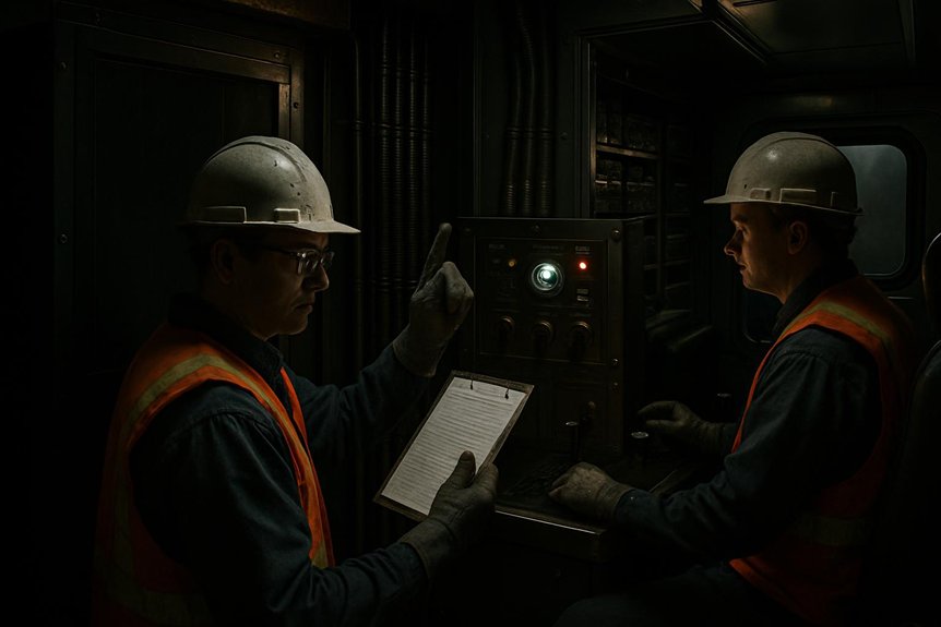
You’ll preserve HEP continuity by using MU pass-through or rescue power when onboard sources fail.

At terminals, you’ll apply wayside shore power through verified isolation and connection procedures.

Scheduled testing and maintenance will confirm transfer logic, protection, interlocks, and crew response readiness.

MU pass-through and rescue

When onboard HEP sources failMU pass-through lets the F125 receive hotel power from another locomotive through approved jumper connections and controls. You must verify compatible voltage, frequency, phasing, ratings, and trainline integrity before energizing the consist. Isolation procedures prevent backfeed, unintended paralleling, and personnel exposure during connection.

  1. Confirm the failed unit, open its source breakers, and apply required lockout controls.
  2. Inspect jumper condition, connector seating, grounding, and communication between operating crews.
  3. Close pass-through controls only after authorization, then monitor current, voltage, alarms, and thermal margins.

Your crew should maintain essential lighting, ventilation, communications, and control systems within the supplying locomotive’s capacity. Load shedding remains necessary if demand exceeds available HEP. Rescue planning should identify compatible locomotives, qualified personnel, recovery routes, and passenger-management steps. Afterward, record alarms, operating duration, and test results for corrective maintenance. Never bypass interlocks or improvise connections.

Wayside shore power

At a terminal, wayside shore power can stabilize passenger services after onboard HEP sources become unavailable. You’ll connect an approved external supply through the designated interface, following site isolation and authorization procedures. The connection supports hotel loads while you protect the locomotive from backfeed, phase errors, and unsafe paralleling. Confirm onboard sources remain isolated before energizing the shore circuit. Coordinate with dispatch, terminal staff, and train crews, because an incorrect sequence can interrupt lighting, ventilation, communications, or passenger information.

RiskControlOperational result
BackfeedApply lockout and verify isolationProtects personnel
Phase mismatchConfirm supply compatibilityPrevents equipment damage
OverloadPrioritize essential loadsPreserves critical services
Loss of shore powerPrepare controlled retransferLimits interruption

You should maintain a documented fallback: secure nonessential loads, notify passengers, and prepare battery-backed communications. Treat wayside power as a contingency, not a replacement for onboard HEP redundancy. Record source status and crew indications throughout the transfer.

Testing and maintenance

Reliable HEP continuity depends on disciplined testing beyond onboard hardware. You should schedule periodic drills that simulate inverter tripsauxiliary genset transfersplit-bus isolation, and MU pass-through. These exercises expose timing, communication, and crew-response risks before service disruption.

  1. Test breakers: Verify protective-relay operation, interlocks, transfer logic, synchronization, and load-shedding tiers under controlled conditions.
  2. Inspect contingencies: Confirm wayside-power connections, rescue procedures, essential-load definitions, and documented isolation steps.
  3. Update controls: Apply validated firmware updates, then repeat acceptance tests, event-log reviews, and failover demonstrations.

You should record results against maintenance intervals, configuration baselines, and compliance requirements. Technicians must investigate nuisance trips, overheating, abnormal transfer times, or failed indications immediately. Procurement teams should require traceable test records and replacement support. This discipline reduces single-point exposure and strengthens HEP continuity across degraded operating scenarios.

Frequently Asked Questions

Which Certifications Govern F125 HEP Redundancy Acceptance and Documentation?

You’ll typically govern F125 HEP redundancy acceptance through FRA regulations, applicable APTA standards, IEEE power-quality practices, and the locomotive’s approved safety and design basis. Certification requirements can also include EMC, fire, electrical shock, and software assurance evidence, depending on contract scope and operating jurisdiction. Require documented failure-mode analysisprotective-relay tests, transfer-sequence validation, insulation results, load-shed verification, and traceable configuration control. Don’t accept supplier claims without witnessed testing and signed records.

How Should Procurement Teams Compare Lifecycle Costs for Redundant HEP Components?

How should you compare lifecycle costs for redundant HEP components? Build a total-cost model, not a purchase-price table. Include acquisition, installation, commissioning, energy use, inspections, spares, software support, overhaul intervals, and disposal. Then quantify downtime exposure, passenger-service disruption, and failure-response labor. Compare inverter and auxiliary-genset scenarios using reliability data, warranty terms, and maintainability targets. You’ll identify the lowest-risk option, even when its initial price exceeds alternatives.

What Spare Parts Strategy Supports Long-Term F125 HEP Availability?

You’ll protect long-term F125 HEP availability with a risk-ranked spares strategy covering inverters, auxiliary genset components, contactors, relays, sensors, cooling hardware, and control modules. Stock serialized, configuration-controlled parts according to failure rates, lead times, and fleet criticality. Maintain preservation, inspection, and traceability records. Include repairable-unit exchange pools and approved substitutes. Validate every replacement through insulation, protection, synchronization, and load-transfer tests before return to service.

How Are HEP Control-System Software Updates Validated Before Fleet Deployment?

You validate HEP control-system software updates through staged, evidence-based testing before fleet deployment. First, you’ll review requirements, cybersecurity controls, interfaces, and fail-safe logic. Next, hardware-in-the-loop testing simulates inverter faults, auxiliary genset transfers, load shedding, MU pass-through, and split-bus isolation. Engineers then conduct laboratory integration and controlled locomotive trials. Independent reviewers assess results against approved acceptance criteria. Finally, you’ll authorize phased release, monitor diagnostics, and retain rollback capability for safe, reliable fleet operation.

Which Supplier Records Help Verify Replacement Inverter and Generator Component Traceability?

You should obtain certificates of conformitymanufacturer part numbers, serial-number records, lot codes, and supplier invoices. Request material certificates, inspection reports, repair histories, and authorized-distribution evidence. Confirm each record matches the component, locomotive, purchase order, and installation date. Preserve receiving inspections, firmware versions, and test results within your asset system. This chain supports HEP continuity, detects counterfeit parts, and enables targeted recalls. Require supplier quality agreements defining retention, access, and audit rights.
Why Your Railroad Head-End Power Choice Matters

Why Your Railroad Head-End Power Choice Matters

On EMD F125 locomotives, you manage hotel loads through a dedicated diesel-alternator HEP system that supplies regulated 480-volt AC independently of traction power. This preserves passenger comfort during idling, shutdowns, and propulsion faults, but adds weight, capital cost, packaging demands, and separate maintenance. A PTO-driven system shares the prime mover, reducing equipment and acquisition cost, yet couples hotel power to engine operation, increasing fuel penalties, mechanical inspection complexity, and fault exposure. Further analysis clarifies lifecycle and fleet-selection tradeoffs.

How Is HEP Generated and Managed on the EMD F125 Locomotives, and What Are the Tradeoffs Between Dedicated HEP Sets and PTO-Driven Solutions?

Head-end power generation relies on distinct mechanical architectures. Dedicated diesel generators provide independent electrical output for passenger cars. This ensures consistent voltage regardless of locomotive traction demands. Power take-off systems draw energy directly from the main engine. Such integration reduces overall fuel consumption during stationary operations. However, it introduces complex thermal management challenges for engineers.

Procurement specialists must weigh initial capital costs against operational efficiency. Dedicated sets offer superior redundancy for critical passenger services. They isolate hotel loads from primary propulsion failures effectively. Conversely, PTO-driven solutions minimize maintenance points and weight. The choice depends heavily on specific route requirements. Mountainous routes benefit from the torque availability of main engines. Flat terrain operations may favor the simplicity of dedicated units.

Reliability metrics drive the final decision for rail operators. Both systems require rigorous monitoring for optimal performance. Modern control systems manage load sharing seamlessly today. Engineers prioritize system uptime above all other factors. Passenger comfort dictates strict power quality standards always. Voltage fluctuations must remain within tight tolerances continuously. Harmonic distortion impacts sensitive onboard electronic equipment negatively. Proper filtering is essential for both architectural approaches. Maintenance schedules differ significantly between the two options.

Dedicated units allow for isolated servicing without downtime. PTO systems require coordinated shutdowns for comprehensive inspections. Cost-benefit analyses reveal long-term savings vary by usage. High-mileage corridors often justify the complexity of PTO. Low-frequency services benefit from the robustness of dedicated sets. Ultimately, the decision balances technical capability with economic reality.

Key Takeaways

  • The EMD F125 uses a dedicated diesel-generator set to supply stable 480-volt AC HEP independently of the traction engine.
  • HEP capacity must cover lighting, HVAC, galley equipment, battery charging, controls, peak demand, continuous loads, and starting surges.
  • Dedicated HEP supports passenger service during idling, shutdown, or propulsion faults, but generator failure can remove hotel power without standby capacity.
  • PTO-driven HEP reduces equipment duplication, but couples hotel power to engine speed, traction loads, torsional vibration, and prime-mover failures.
  • Reliable HEP management requires voltage, frequency, phase-balance, harmonic, cooling, protection, and transfer-system verification under all operating conditions.

Fundamentals of Locomotive Hotel Load Systems

hep power system architectures

You define railroad head-end power requirements by matching passenger loads, voltage stability, frequency, and redundancy targets.

Next, you compare dedicated generator architectures, which isolate locomotive auxiliary power from traction demands.

You then assess PTO-driven HEP, integrating generation with the prime mover while adding thermal and control-system dependencies.

Defining railroad head-end power requirements

For passenger rail, railroad head-end power must deliver stable 480V AC or 600V DC to onboard hotel loads. You must size this supply for lighting, HVAC, galley equipment, battery charging, and control electronics. These loads operate separately from traction power, so passenger comfort can’t depend on locomotive speed or tractive effort.

First, define peak demand, continuous demand, and starting surges across the consist. Then evaluate voltage regulation, frequency stability, phase balance, and allowable harmonic distortion. Your design should preserve service quality during acceleration, coasting, idle periods, and station stops.

Additionally, specify protection against overloads, short circuits, ground faults, and transient disturbances. Locomotive auxiliary power controls should monitor load changes and communicate alarms to maintenance teams. Finally, verify connector ratings, cable capacity, cooling requirements, and compatibility with passenger-car distribution equipment before selecting equipment.

Overview of dedicated generator architectures

When specified correctly, a dedicated locomotive generator uses an independent diesel engine coupled directly to an alternator. You receive railroad head-end power without depending on the traction prime mover. This architecture supports hotel loads while the locomotive idles, shuts down, or experiences propulsion-related faults. A dedicated hep set typically includes fuel supply, cooling, exhaust, starting, controls, protection, and power-conditioning equipment.

You can isolate these subsystems for inspection, preserving locomotive availability and passenger-service continuity. Independent regulation also helps maintain voltage and frequency during changing coach loads. However, you must allocate space, weight, mounting structure, and additional service intervals. The installation consequently affects packaging and axle-load calculations. Compared with pto-driven hep, this design adds a complete engine-generator system, but it preserves functional separation. Proper redundancy and monitoring strengthen reliability for demanding passenger operations.

Mechanics of PTO-driven HEP solutions

A PTO-driven HEP system uses a shaft connected to the main diesel engine’s crankshaft. You transfer rotational power to an alternator, which produces railroad head-end power while the prime mover runs. This architecture reduces separate engines, mounts, fuel systems, and some maintenance points. However, you must manage thermal loading, torsional vibration, and traction-load interactions carefully. Your controls regulate voltage, frequency, excitation, filtering, and load transitions. Harmonic distortion requires dedicated mitigation to protect passenger equipment.

MechanismEngineering implication
Crankshaft shaftingShares prime-mover torque
Direct alternator driveRequires engine operation
Integrated coolingIncreases thermal coordination
Power electronicsControls voltage quality
Common controlsAdds software complexity

During station stops, PTO operation can improve fuel utilization, but idling remains necessary. Consequently, failures affecting the prime mover can remove both traction and hotel power. You should evaluate redundancy, axle loading, retrofit access, and total downtime before selecting this railroad head-end power architecture.

Operational Efficiency and Fuel Consumption

idle fuel burn comparison analysis

You’ll compare idle fuel burn in dedicated and PTO-driven railroad head-end power configurations.

You’ll then assess load matching, prime-mover optimization, and control strategies across operating conditions.

Finally, you’ll evaluate how each architecture shapes emissions from the EMD F125 locomotive.

Fuel burn rates in idle modes

At idle, a dedicated generator usually burns less fuel than a large prime mover supplying railroad head-end power. You can isolate locomotive auxiliary power demand from the traction engine, avoiding unnecessary main-engine operation. A dedicated HEP set thus sustains passenger services with lower fuel consumption during extended station stops. By contrast, a PTO-driven HEP system draws power from the prime mover, which must remain running.

The engine typically operates at inefficient low-notches while producing modest hotel-load output. Consequently, specific fuel consumption rises even though the locomotive remains stationary. Your route profile matters: frequent stops and long layovers magnify this penalty. A dedicated set can reduce idle fuel burn and associated emissions in those conditions. However, you should evaluate fuel savings alongside installation, service, and packaging requirements before selecting the architecture for your F125 fleet.

Load matching and engine optimization

When hotel loads vary, dedicated sets can match generator capacity closely, improving railroad head-end power efficiency. You can operate these auxiliary engines near their efficient design point, even when traction demand changes. By contrast, a PTO-driven HEP system must coordinate the main prime mover’s speed, torque, and traction output. That requirement can force inefficient operating points when hotel demand is modest or fluctuating.

ArchitectureLoad-matching consequence
Dedicated HEP setClosely follows hotel demand
PTO-driven HEPShares the main engine’s operating point
Variable loadsDedicated control limits wasted capacity
High traction demandPTO availability may improve
Control strategyMonitoring prevents unstable transitions

Your control system should prioritize stable voltage while adjusting generator output. During sustained high traction, PTO operation may use available engine capacity effectively. However, low hotel loads can leave the prime mover oversized for auxiliary demand. Consequently, you’ll compare route profiles, duty cycles, and load records before selecting an architecture.

Emissions impact of HEP generation methods

Load matching also shapes the emissions profile of railroad head-end power. You’ll reduce fuel use when HEP production follows passenger-load demand. However, idling the F125’s large prime mover can produce more NOx and particulate matter per kilowatt-hour than an optimized auxiliary generator. That difference directly affects station air quality, regulatory exposure, and lifecycle cost.

  1. Dedicated HEP sets: You can operate smaller engines near efficient load points, reducing emissions during stops and low hotel-load periods.
  2. PTO-driven HEP: You’ll avoid a separate engine, but lightly loaded main-engine operation may worsen emissions intensity.
  3. Control optimization: You can coordinate load sharing, shutdowns, and filtering to limit fuel burn and passenger-service interruptions.

Your procurement model should compare route profiles, stop duration, hotel-load variability, and emissions requirements. Regulatory pressure increasingly favors cleaner HEP sources. Mikura International can help you evaluate auxiliary-power architectures against measured operating data, maintenance constraints, and future compliance targets.

Maintenance Reliability and Lifecycle Costs

hep service cycles and reliability

You’ll assess dedicated HEP set service intervals against the EMD F125’s operating cycles and maintenance access. You’ll also evaluate PTO-driven HEP linkages, including alignment, lubrication, thermal stress, and inspection requirements. Finally, you’ll compare failure modes and redundancy strategies to quantify reliability, downtime exposure, and lifecycle cost.

Service intervals for dedicated HEP set units

A dedicated HEP set follows its own service intervals for oil changes, filter replacements, inspections, and testing. You’ll manage these tasks separately from traction-engine maintenance, increasing the locomotive’s total maintenance burden. However, this separation creates valuable operational flexibility because technicians can service the unit without removing traction power from availability.

  1. Oil and filter control: You’ll protect engine performance by tracking lubricant condition, filter loading, and contamination trends.
  2. Inspection discipline: Your team should verify generator output, cooling performance, wiring integrity, and protective-device operation at scheduled intervals.
  3. Reliability planning: You’ll reduce surprise failures by aligning inspections with operating hours, duty cycles, and recorded fault history.

Modular repairs can shorten corrective downtime because technicians isolate the dedicated unit. Meanwhile, planned intervals support predictable labor, parts demand, and lifecycle budgeting. For passenger service, consistent scheduling helps preserve railroad head-end power availability and onboard comfort.

When the main engine drives railroad head-end power, clutches, shafts, and bearings add mechanical interfaces. You must inspect each interface for alignment, lubrication, wear, and thermal growth. These links transmit torque through changing engine speeds and passenger-load demands. As a result, your maintenance team needs specialized procedures beyond routine prime-mover servicing. Access constraints can extend inspection time, especially within crowded locomotive packaging.

During major overhauls, you’ll coordinate PTO inspections with engine removal, drivetrain measurements, and control-system verification. That coordination can increase labor hours and shop scheduling pressure. Replacement parts also require careful dimensional control, because small alignment errors accelerate bearing or coupling wear. Over the lifecycle, these requirements may offset PTO benefits in weight and fuel use. You should thereupon model labor, planned downtime, tooling, and overhaul intervals before selecting PTO-driven HEP for an EMD F125 fleet.

Failure modes and redundancy strategies

Because railroad head-end power supports passenger safety and comfort, redundancy must match each architecture’s failure modes. When you assess the EMD F125, separate hotel-load failures from propulsion risks. A dedicated HEP set isolates passenger power from the main engine, but one failed generator can remove hotel power without standby capacity. PTO-driven HEP reduces equipment count and weight, yet shaft, clutch, or converter failures can affect main-engine operation. You should evaluate three safeguards:

  1. Install standby generation or automatic transfer capability for uninterrupted passenger service.
  2. Monitor bearings, couplings, converters, voltage, frequency, and harmonic distortion continuously.
  3. Coordinate shutdown procedures, spares, and recovery plans with maintenance control.

Dedicated sets simplify fault isolation and scheduled servicing. PTO systems demand integrated diagnostics and thermal protection. Your lifecycle model must price downtime, inspections, redundancy hardware, and passenger-comfort penalties—not merely purchase cost.

Engineering Trade-offs and Design Constraints

head end power weight tradeoffs

You must balance railroad head-end power equipment weight against axle-loading limits and available locomotive space. You’ll also manage confined-space heat rejection without compromising propulsion or passenger-service reliability. Meanwhile, you need harmonic filtering and voltage regulation to protect sensitive onboard systems.

Weight distribution and axle loading limits

Weight distribution directly affects railroad head-end power integration, adhesion, and axle-load compliance. You must evaluate each EMD F125 installation as a complete locomotive system. A dedicated HEP set adds mass high or toward one end, potentially shifting bogie reactions. That shift can reduce available adhesion or exceed route-specific axle limits.

PTO-driven HEP usually weighs less, but you’ll need robust shaft supports and precise alignment. Structural reinforcement can relocate loads and complicate certification.

  1. Axle loading: Verify static and dynamic loads against infrastructure limits.
  2. Adhesion: Protect tractive effort when passenger demand and gradients coincide.
  3. Serviceability: Prevent component placement from obstructing inspections or access.

You should model fuel, equipment, and passenger-car loads together. Mikura International can help you validate interfaces before procurement. This disciplined approach reduces approval risk, wheel-load imbalance, and costly redesigns across aging fleets.

Thermal management in confined spaces

Thermal management is a decisive engineering constraint in railroad head-end power installations. You must remove heat reliably within restricted locomotive compartments, where airflow, radiator area, and service access remain limited. A dedicated HEP set uses its own cooling loop, radiator, pump, and controls. This architecture isolates hotel-load heat from the propulsion engine’s cooling circuit. However, it adds equipment, ducting, coolant, and maintenance interfaces inside confined spaces.

A PTO-driven HEP system shares the main engine’s radiator and cooling infrastructure. That arrangement can reduce component count and installation weight, but it increases the prime mover’s thermal burden. During hot-weather operation, sustained passenger loads may challenge available cooling capacity. You should thus assess radiator margins, airflow paths, coolant temperatures, and derating thresholds. Compartment layout also affects inspection time and failure recovery.

Electrical quality and harmonic filtering needs

When passengers rely on stable service, railroad head-end power must protect sensitive electronics from voltage spikes and harmonics. On an EMD F125, you should evaluate waveform quality as a system constraint, not an accessory.

  1. Dedicated HEP sets typically deliver cleaner, regulated output, simplifying filters and protecting displays, chargers, and control networks.
  2. PTO-driven HEP draws power from the main alternator, but advanced inverters must condition variable voltage and frequency.
  3. Filtering controls risk through reactors, capacitors, active filters, shielding, and continuous harmonic monitoring.

Your design must coordinate generator controls, inverter switching, grounding, and passenger-car loads. Poor coordination can create resonance, nuisance trips, overheating, or uncomfortable lighting fluctuations. Conversely, excessive filtering adds weight, losses, maintenance, and enclosure demands. Validate total harmonic distortion across traction transitions, idle operation, and maximum hotel load. This testing supports reliability, passenger comfort, and defensible procurement decisions.

hybrid hep vs operational savings

You’ll compare capital expenditure with operational savings when selecting railroad head-end power for EMD F125 fleets. Hybrid energy storage can reduce peak loads, emissions, and generator cycling, but it adds controls and integration requirements. Your decision should align HEP architecture with route duty cycles, maintenance capability, reliability targets, and passenger power-quality standards.

Capital expenditure versus operational savings

Although dedicated railroad head-end power systems require higher capital expenditure, they can deliver predictable lifecycle costs. You’ll fund an additional engine, generator, controls, and installation, increasing the EMD F125’s acquisition price. However, independent operation can reduce traction-engine wear, simplify scheduled servicing, and preserve passenger power during propulsion faults.

PTO-driven HEP lowers initial procurement cost because you share the prime mover. Yet you’ll accept greater integration complexity, coordinated shutdowns, and potentially higher fuel and maintenance expenses over the locomotive’s service life. Evaluate each option through three cost pressures:

  1. Capital: Can your fleet budget absorb a dedicated HEP set?
  2. Operations: Will route hours and hotel-load demand justify PTO efficiency?
  3. Risk: Can you finance downtime when shared equipment fails?

Use duty-cycle modeling, failure data, and maintenance labor rates to validate total ownership cost. This approach supports defensible procurement decisions.

Integration with hybrid energy storage systems

Hybrid energy storage can buffer railroad head-end power loads, letting the prime mover or dedicated generator shut down during low-demand periods. You can reduce fuel consumption and emissions substantially during station stops and hotel-load transients. Batteries absorb short-duration peaks, then release energy when passenger demand rises. As a result, your control system must coordinate battery state-of-charge, generator dispatch, traction auxiliaries, and trainline voltage. Power converters regulate voltage and frequency while limiting harmonic distortion for sensitive passenger equipment.

Thermal management remains essential because repeated cycling produces heat within cells, inverters, and cooling circuits. You’ll also need protection logic for isolation faults, thermal runaway, overcurrent, and degraded battery capacity. Hybridization can preserve redundancy by retaining a generator or PTO path as backup. Procurement should therefore specify lifecycle testing, software interfaces, fire protection, and service support. Mikura International can help you evaluate integration risks across aging locomotive electrical architectures and future upgrades.

Selecting the right HEP solution for your fleet

Battery buffering can reduce peak demand, but fleet selection still depends on route duty cycles and operating constraints. You should evaluate dwell times, traction demand, ambient conditions, and regulatory requirements together. High-utilization freight-passenger routes may favor PTO-driven HEP, because the prime mover shares fuel and reduces equipment weight. However, dedicated HEP sets can protect passenger service when propulsion faults occur, strengthening redundancy and simplifying isolated maintenance.

  1. Reliability: Choose dedicated sets where passenger comfort, voltage stability, and recovery time dominate risk.
  2. Efficiency: Select PTO when sustained utilization offsets thermal, control, and integration complexity.
  3. Future readiness: Specify battery buffering, harmonic filtering, diagnostics, and upgradeable controls.

Your procurement model should compare capital cost, fuel consumption, overhaul intervals, emissions, axle loading, and software support. Require measured power quality and failure-mode data. For older locomotives, verify structural, cooling, and control-system compatibility before approving retrofit work.

Frequently Asked Questions

What Voltage and Frequency Does the EMD F125 Supply to Passenger Coaches?

You’ll find the EMD F125 supplies passenger coaches with 480 volts AC at 60 hertz through its railroad head-end power system. Think of this output as the train’s electrical heartbeat, supporting lighting, heating, ventilation, air conditioning, kitchen equipment, and onboard controls. You should verify coach compatibility, phase configuration, maximum load, and protection settings against operating documentation. Proper regulation and filtering help maintain passenger comfort and protect sensitive electronics throughout service.

How Does HEP Power Quality Affect Onboard Signaling and Passenger Information Systems?

HEP power quality directly affects onboard signaling and passenger information systems. You need stable voltage and frequency because fluctuations can reset displays, interrupt announcements, or disrupt trainline communications. Excessive harmonic distortion may corrupt data networks, audio amplifiers, and signaling interfaces. Hence, your maintenance team should monitor transients, insulation faults, grounding, and total harmonic distortion. Proper filtering, shielding, surge protection, and redundant converters help preserve reliable operation, passenger comfort, and safety-critical communications.

Which Safety Interlocks Protect Passengers During HEP Connection and Disconnection?

You protect passengers with interlocks that verify zero trainline voltage before coupling or uncoupling HEP cables. Ground-fault relays, phase-sequence checks, circuit breakers, and connector pilot contacts prevent energized separation. Door and receptacle switches confirm secure connections, while control logic blocks traction changes during transfers. For example, during a station stop, your system isolates the locomotive, confirms discharge, then permits uncoupling. These safeguards reduce arcing, shock exposure, and passenger-car equipment damage.

How Are HEP Faults Isolated Without Interrupting Locomotive Traction Power?

You isolate railroad head-end power faults through dedicated breakers, contactors, and protection relays, while traction systems remain energized. Differential, overcurrent, ground-fault, and undervoltage detection identify defective feeders or loads. The control system trips only the affected HEP section, records diagnostics, and prevents automatic re-energization until conditions normalize. Dedicated auxiliary converters or generator sets further separate hotel loads electrically. This architecture preserves locomotive movement, but passengers may lose lighting or climate control temporarily.

What Inspection Records Should Procurement Teams Request for an F125 HEP System?

Request complete F125 HEP inspection records: operating hours, load profiles, fault logs, insulation-resistance tests, and voltage-quality measurements. Ask for generator, inverter, transformer, cooling-system, and wiring inspection reports, including corrective actions and technician sign-offs. Require protection-relay tests, harmonic-distortion results, emergency-shutdown verification, and software revision histories. Like reading a locomotive’s maintenance diary, compare trends rather than isolated results. You’ll also need component replacement records, warranty claims, and unresolved defects before procurement approval.

You may also like to read – Sizing and Energy Management of a Hybrid Locomotive Based on Flywheel and Accumulators

Translate »