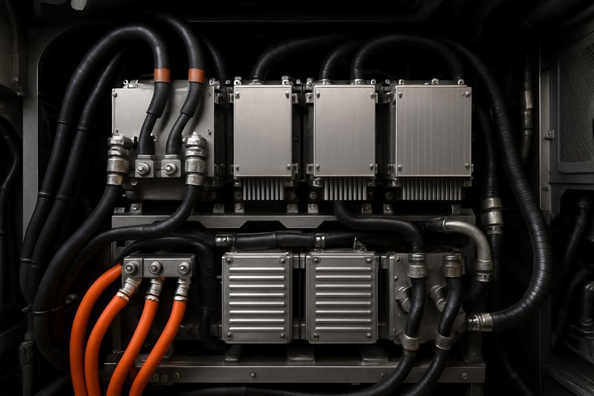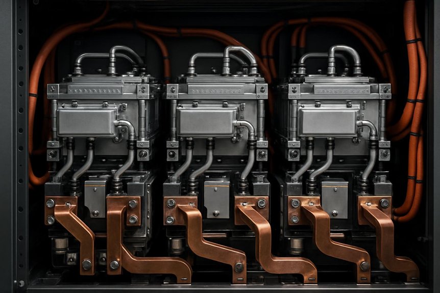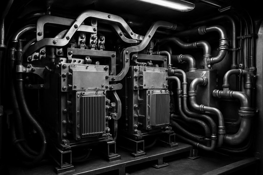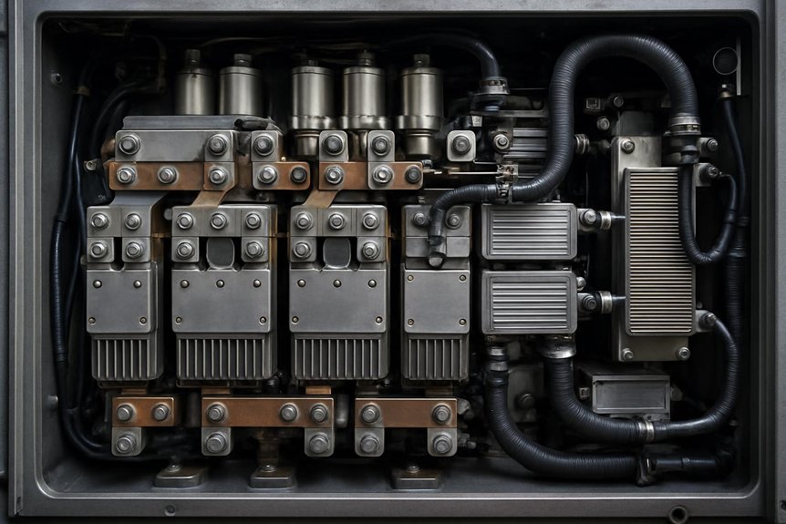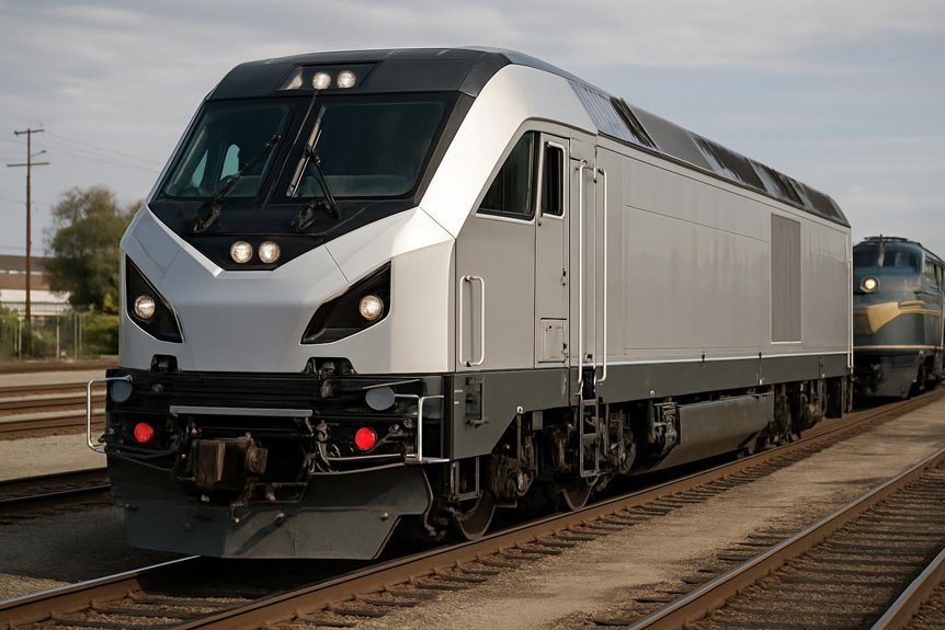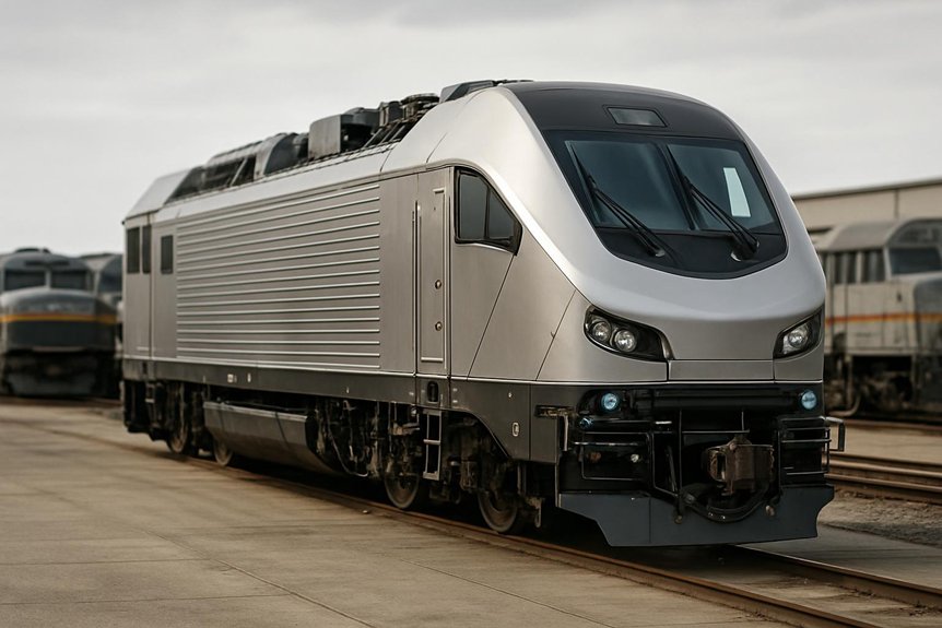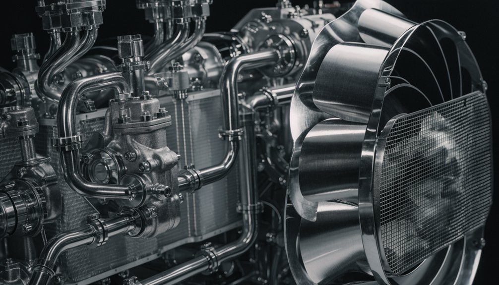
What Makes EMD F125 Traction Inverter Topology Remarkably Better

What Makes EMD F125 Traction Inverter Topology Remarkably Better

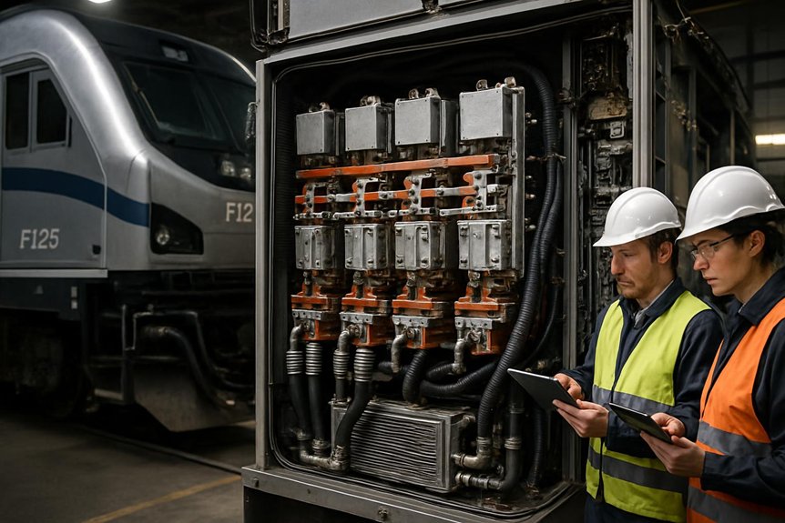
EMD F125 Traction Inverter Topology: You’ll find the EMD F125 uses a high-power voltage source inverter topology: rectified alternator output feeds a DC link, then three-leg IGBT inverter bridges create controlled three-phase AC for each traction motor. This setup improves torque control, adhesion, and regenerative braking while limiting wasted energy through optimized PWM or space-vector modulation. It also concentrates heat in managed power modules, supports liquid cooling, and enables modular fault handling. Next, you’ll see how those benefits affect lifecycle cost.

What traction inverter topology is used on the EMD F125, and how does it impact efficiency, thermal management, and reliability?

The EMD F125 uses a modern three-phase voltage source inverter topology with AC traction motors. This topology switches high DC link voltage into controlled three-phase waveforms for each traction motor. For procurement teams, understanding this choice clarifies lifecycle costs, thermal margins, and maintenance implications in high‑duty passenger service.

Efficiency is driven by semiconductor selection, PWM strategy, and DC link design. High efficiency reduces fuel burn and alternator loading for 125 mph operation. Lower switching and conduction losses translate into smaller cooling packages, lighter inverter cabinets, and more space for other locomotive systems. This directly influences total cost of ownership and energy budget planning.
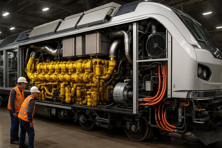
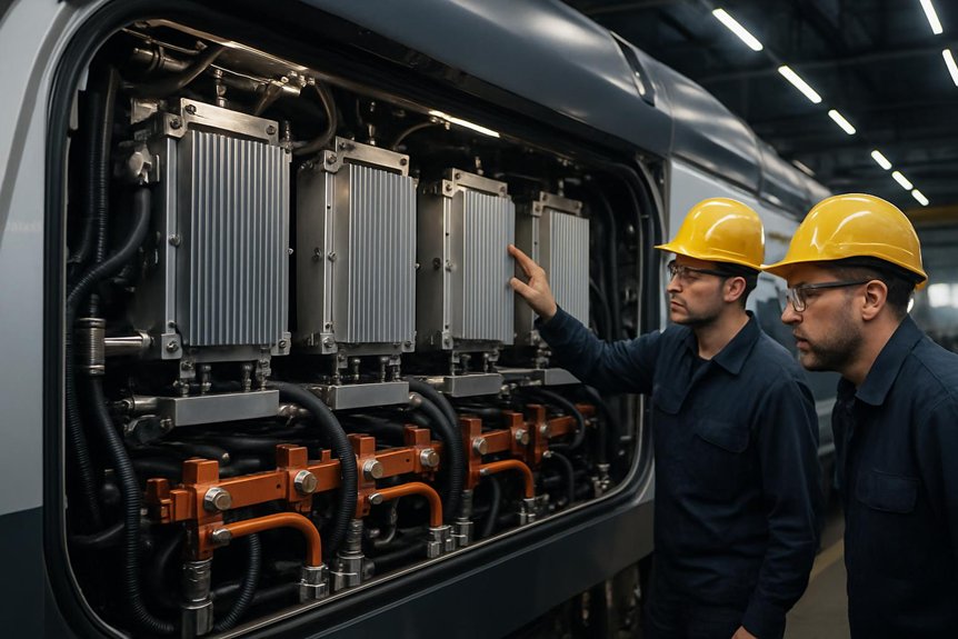
Thermal management relies on liquid cooling, optimized busbar layout, and robust gate drive control. Stable junction temperatures improve reliability, extend IGBT or SiC device life, and minimize nuisance trips. Redundant protection, conservative de‑rating, and modular power stacks enhance system availability and simplify field replacement for fleet operators.

Key Takeaways

  • The EMD F125 uses a DC-link-fed three-phase voltage source inverter to supply controlled AC power to each traction motor.
  • Alternator AC is rectified into a high-voltage DC link, then traction inverters modulate voltage, frequency, and phase for torque control.
  • IGBT-based PWM or space-vector modulation reduces torque ripple, improves adhesion control, and supports efficient part-load operation.
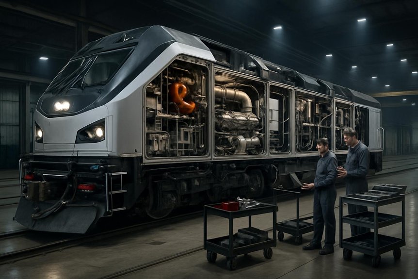
  • Inverter efficiency depends on conduction and switching losses, affecting fuel use, DC-link stress, cooling load, and sustained high-speed performance.
  • Reliability depends on liquid cooling, modular power stacks, fault protection, diagnostics, and resistance to vibration, heat, moisture, and contamination.

Understanding the EMD F125 Power Flow

prime mover to dc link control | EMD F125 Traction Inverter Topology

You start with the prime mover driving the alternator, which feeds a high-voltage DC link and then route that energy through traction inverters to control the AC traction motors. You also integrate a separate HEP inverter, so passenger loads stay coordinated with propulsion demand.

Start with the power source: the F125’s Caterpillar prime mover drives the main alternator, which produces high-power three-phase AC for the locomotive’s electrical system. You can view this stage as the mechanical-to-electrical conversion point in the emd f125 traction inverter topology. The alternator output isn’t sent directly to the motors. Instead, rectifiers convert that AC into a controlled, stable DC link.

That DC link matters because it acts as the common electrical bus. You feed traction power from it, and you also support auxiliary inverter loads serving onboard systems. By stabilizing voltage before downstream conversion, you reduce control complexity and protect connected equipment. For rail engineers, this architecture helps separate engine speed, alternator output, and inverter demand while supporting consistent passenger-service performance under changing load conditions.

Traction inverters and AC traction motors

From the DC link, each voltage source inverter converts stable DC power into controlled three-phase AC for its traction motor. You get precise torque control because the inverter adjusts voltage, frequency, and phase in real time. This EMD F125 traction inverter topology lets each motor respond quickly to commanded tractive effort.

You also gain coordinated control across the locomotive. The traction control system compares axle speed, load, and adhesion conditions, then commands each inverter to reduce slip and maintain acceleration. At higher speeds, that same coordination supports smooth speed regulation and balanced motor loading.

For rail operators, traction inverter efficiency in locomotives matters because cleaner power conversion reduces electrical losses before energy reaches the rails. You’ll see better use of alternator output, steadier performance, and less stress on traction motors.

Separate HEP inverter and system integration

Alongside the traction inverters, the EMD F125 uses an independent 1,000 kW inverter for head-end power to the passenger consist. You keep hotel loads separate from propulsion, so lighting, HVAC, and onboard systems receive stable power during acceleration, braking, and station dwell.

FunctionSeparate inverter roleOperational value
TractionFeeds AC motorsPreserves propulsion control
HEPSupplies consist loadsStabilizes passenger services
DC linkShares source energyBalances demand
ControlsCoordinates limitsPrevents overloads
DiagnosticsTracks faultsSpeeds maintenance

This integration supports EMD F125 traction inverter topology because you can tune traction and HEP priorities independently. That improves power quality, reduces nuisance trips, and strengthens reliability of ac traction systems in passenger locomotives.

EMD F125 Traction Inverter Topology Explained

three phase pwm traction inverter

You can view the EMD F125 traction inverter topology as a three-phase voltage source inverter architecture feeding AC traction motors. You’ll see how switching devices and PWM control shape torque, efficiency, and thermal load. You’ll also compare this approach with legacy DC drive and GTO-based locomotive inverters.

Voltage source inverter architecture

Although implementation details can vary by equipment package, the EMD F125 traction inverter topology is best understood as a three-phase voltage source inverter. You start with a high-voltage DC link from the alternator rectification stage, then feed each AC traction motor through a standard three-leg bridge. Each leg uses two controlled switches, creating the phase outputs needed for precise motor torque.

You’ll also find DC link capacitors stabilizing voltage during load changes, low-inductance busbars carrying high current, and gate-drive electronics coordinating safe device operation. This architecture matters because clean power flow reduces electrical stress. It also supports locomotive thermal management and cooling systems by limiting unnecessary heat generation. For rail teams, that means more predictable performance, easier diagnostics, and stronger component life in passenger service.
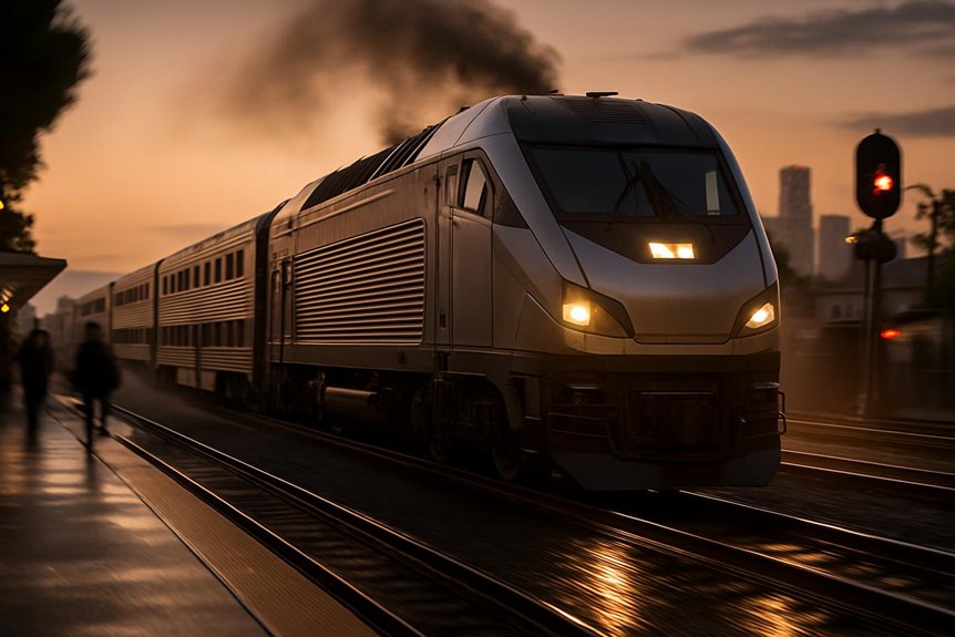
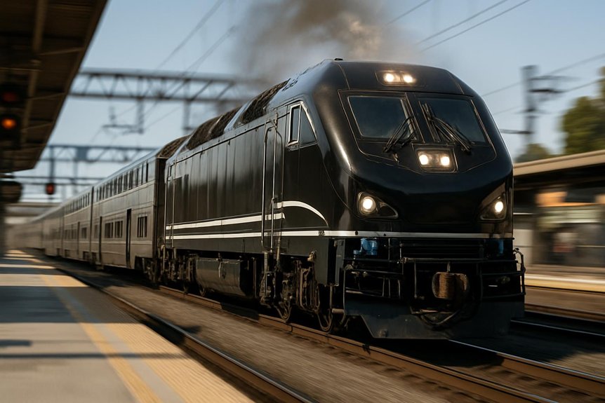
Switching devices and modulation strategy

Most EMD F125 traction inverter topology discussions point to high-power IGBT switching devices for rail-duty conversion. You typically see modules rated in the kilovolt range, with high current capacity for sustained passenger service. These devices switch the DC link into controlled three-phase output for AC traction motors.

ElementTypical roleWhy it matters
IGBT moduleSwitches DC linkHandles rail loads
Gate driveControls turn-onLimits stress
PWM patternShapes voltageSmooths current
SVPWM optionUses DC bus wellImproves torque
Protection logicDetects faultsReduces damage

You’ll usually evaluate sinusoidal PWM or space-vector modulation. Both strategies shape motor currents, reduce torque ripple, and support precise adhesion control. That improves traction inverter efficiency in locomotives without adding unnecessary mechanical complexity.

Comparison with legacy locomotive inverters

When compared with older DC chopper drives and GTO-thyristor inverter systems, the F125’s VSI architecture gives rail operators finer motor control and simpler maintenance. You get smoother torque regulation because the EMD F125 traction inverter topology shapes three-phase output with modern PWM control. That matters in passenger service, where acceleration, adhesion, and 125 mph stability affect schedules.

Legacy chopper systems controlled DC motors with higher brush wear and heavier rotating maintenance demands. GTO-based inverters improved AC traction, but they used bulkier devices and slower switching. You now benefit from lighter power electronics, cleaner diagnostics, and more modular replacement paths. For procurement teams, that means fewer specialized overhaul tasks. It also supports better locomotive thermal management and cooling systems, since reduced losses ease cabinet heat load.

How Topology Influences Locomotive Efficiency

emd f125 lower conversion losses

You see the EMD F125 traction inverter topology influence efficiency through lower conversion losses and reduced fuel demand. At 125 mph, it helps manage alternator loading while keeping AC traction motors efficient during part-load operation. You also gain better energy utilization when regenerative braking feeds usable power into HEP loads or braking resistors.
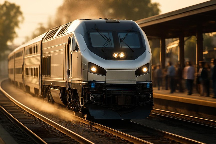
Conversion efficiency and fuel consumption

In high-duty passenger service, conversion efficiency depends on how the inverter manages conduction and switching losses. With the EMD F125 traction inverter topology, you convert DC link power into three-phase motor output while limiting wasted heat. Conduction losses occur as current flows through power devices. Switching losses appear each time devices turn on or off.

  1. You reduce alternator demand when the inverter wastes less energy as heat.
  2. Lower fuel burn because the prime mover supplies more usable traction power.
  3. You improve lifecycle economics through lower energy cost and reduced cooling burden.

For rail engineers, small efficiency gains matter across daily schedules and annual mileage. Higher traction inverter efficiency in locomotives supports better fuel planning, especially under repeated acceleration and station-stop duty cycles without compromising AC traction performance.

High‑speed operation and part‑load behavior

Efficiency gains become more valuable at 125 mph, where sustained cruise power stresses the alternator, DC link, and inverter cooling system. With EMD F125 traction inverter topology, you convert DC link power into stable three-phase motor voltage with fewer wasted losses. That helps you hold schedule speed while limiting heat rise and alternator loading.

At part load, optimized PWM modulation matters just as much. You don’t always run at full output between station stops. You accelerate hard, cruise briefly, then trim power as signals, grades, and dwell patterns change. A voltage source inverter can adjust frequency, voltage, and switching patterns quickly. That improves traction inverter efficiency in locomotives during commuter service profiles. You get smoother torque control, lower thermal cycling, and better use of available engine power.

Regenerative braking and energy utilization

During braking, the AC drive system can reverse power flow and turn traction motors into generators. In the EMD F125 traction inverter topology, the voltage source inverter routes generated energy through the DC link. You can use that energy for head-end power loads when conditions allow, or dissipate it safely through braking resistors.

  1. You reduce friction brake demand, which cuts wheel, disc, and pad wear.
  2. Improve energy utilization by capturing useful braking power inside the train.
  3. You control thermal stress because the inverter manages current, voltage, and resistor loading.

For rail operators, this means less mechanical maintenance and better energy budgeting. It doesn’t make braking losses disappear, but it gives you controlled, predictable energy handling during repeated station stops and downhill operation.
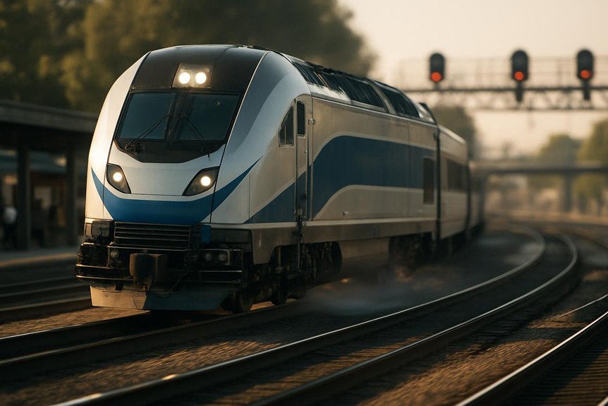
Thermal Management of the F125 Traction Inverter

liquid cooling protects f125 inverter

You manage heat from IGBT power modules, busbars, and gate drives before junction limits reduce inverter life. You’ll see how liquid cooling, sensor placement, and airflow protect the F125 inverter cabinet. Good thermal design keeps AC traction systems available and simplifies maintenance during demanding passenger service.

Heat sources and thermal limits in power modules

As the F125 traction inverter converts DC link power into three-phase AC, its main heat sources sit inside the power modules. In the EMD F125 traction inverter topology, you manage junction heating before it becomes a service risk.

  1. IGBT junctions: You see conduction and switching losses rise with current, PWM frequency, and temperature. That heat narrows safe operating area.
  2. Freewheel diodes: You control reverse-recovery and conduction losses during motor current commutation. These losses matter during acceleration and braking.
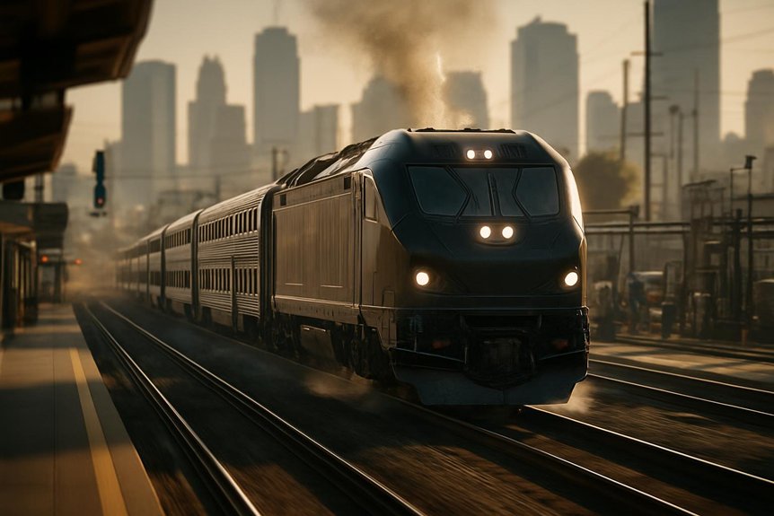
  3. DC link capacitors: You track ripple current heating, because elevated core temperature shortens capacitor life.

Thermal cycling adds another limit. Each load change expands and contracts bonds, substrates, and solder layers. You protect reliability by keeping junction swings within design margins.

Cooling system design and implementation

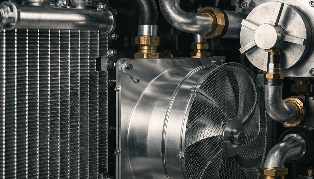
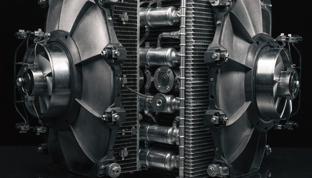
Because inverter heat can quickly become a reliability issue, the F125 uses liquid cooling to move losses away from power modules. You typically see coolant routed through cold plates bonded to IGBT stacks, gate-drive areas, and DC link hardware. This supports the EMD F125 traction inverter topology by keeping semiconductor junctions within defined limits during acceleration, braking, and sustained passenger speeds.

You also need heat exchangers sized for locomotive duty, not light industrial service. Pumps circulate coolant through the inverter cabinet, while fans reject heat to ambient air. Temperature, flow, and pressure sensors give the controls early warning before limits become trips. If coolant flow drops or temperature rises, protection logic can reduce output or isolate the affected section. That protects traction inverter efficiency in locomotives without guessing.
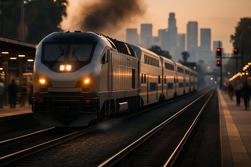
Thermal design impact on availability and maintenance

When the inverter holds stable temperatures, power modules experience less thermal cycling and last longer. In the EMD F125 traction inverter topology, that stability protects IGBT junctions, gate drivers, busbars, and capacitors during fast passenger duty.

You gain availability because fewer temperature swings mean fewer cracked solder joints, loosened bonds, or nuisance thermal trips. Inspection intervals can stretch when coolant condition, flow, and sensor data stay within limits.

  1. You reduce unplanned outages by detecting cooling faults before derating.
  2. Simplify servicing when filters, pumps, hoses, and heat exchangers remain accessible.
  3. You control lifecycle cost by replacing modular cooling items without disturbing power stacks.

For maintenance teams, clear access matters. It shortens troubleshooting, improves repair consistency, and keeps locomotives ready for scheduled service.

Reliability and Procurement Considerations

modular inverter reliability planning

You need modular inverter hardware, redundancy, and fast fault handling to protect availability and also can’t overlook vibration, heat, moisture, and rail-duty cycling when judging environmental robustness. You should weigh lifecycle cost, support quality, and vendor capability before procurement decisions.

Modularity, redundancy, and fault handling

For rail operators evaluating the EMD F125 traction inverter topology, modularity matters as much as efficiency. You need inverter hardware that keeps passenger schedules moving and simplifies depot work. Modular power stacks let your technicians isolate a failed section, remove it, and install a replacement quickly under controlled depot conditions.

  1. Faster recovery: You reduce troubleshooting time because each stack has defined interfaces, sensors, and service points.
  2. Managed fault response: The inverter protects itself through overcurrent detection, overtemperature monitoring, and short-circuit shutdown logic.
  3. Practical redundancy: You limit service disruption by containing faults before they damage adjacent components or traction motors.

You don’t eliminate every failure mode, but you improve maintainability. That supports better availability planning, fewer extended outages, and clearer procurement risk assessment for AC passenger locomotive fleets.

Environmental robustness for rail duty cycles

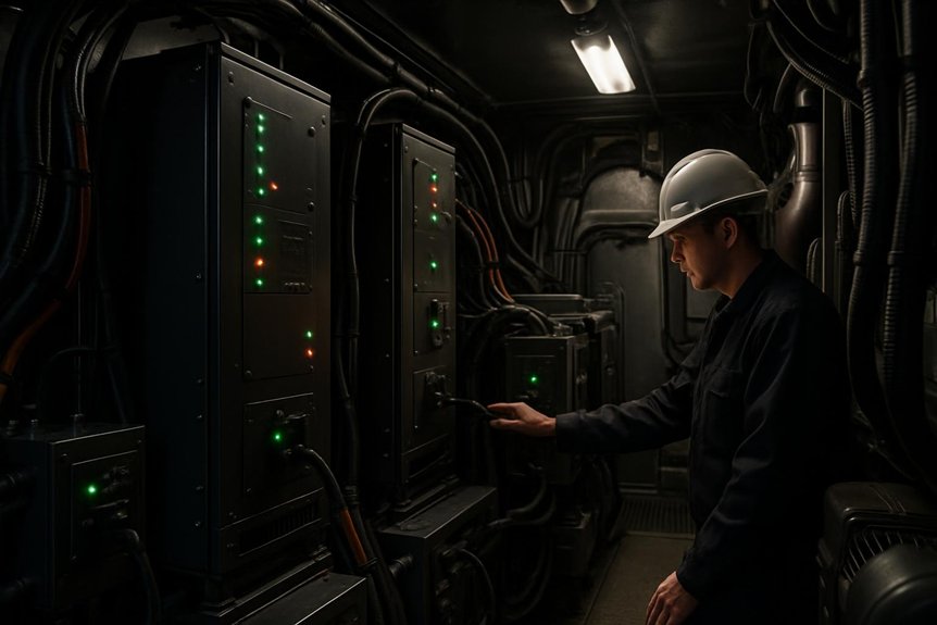
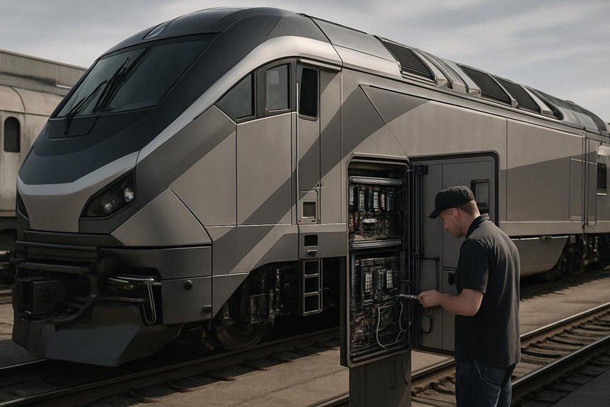
Because passenger locomotives face constant vibration, shock, humidity, brake dust, and conductive contamination, inverter resilience must be proven before procurement. You should verify that the EMD F125 traction inverter topology uses sealed enclosures, conformal-coated boards, rugged busbars, and secure connectors for rail duty.

Testing matters because small weaknesses become service failures. You’ll want evidence of vibration and shock qualification, thermal cycling, humidity exposure, insulation checks, and contamination resistance. These tests confirm that gate drives, sensors, capacitors, and IGBT power modules remain stable over years of starts, stops, and high-speed operation.
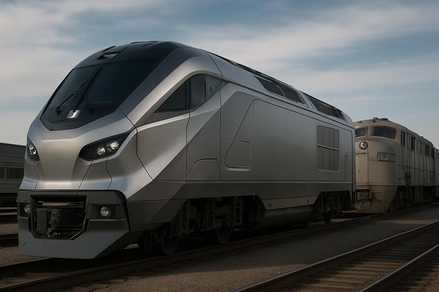
You also need maintainable protection. Filters, pressure monitoring, fault logs, and accessible modules help your team diagnose issues before trips escalate. That’s how reliability of AC traction systems in passenger locomotives becomes measurable.
Evaluating lifecycle cost and vendor options

Environmental robustness only proves part of the business case; lifecycle cost proves the rest. When you evaluate EMD F125 traction inverter topology, connect technical choices to fleet economics. A three-phase voltage source inverter can lower energy losses, cooling stress, and unscheduled removals, but you need evidence before procurement decisions.

Request these vendor data points:

  1. MTBF by module, gate drive, coolant pump, and control electronics.
  2. Efficiency curves across passenger duty cycles, not only peak ratings.
  3. Spares policy, repair turnaround, firmware support, and obsolescence planning.

You’re buying availability, not just hardware. Topology affects total cost of ownership through fuel use, thermal margin, service labor, and inventory strategy. Mikura International helps you review parts support risks honestly, so long-term fleet planning stays practical.

Frequently Asked Questions

Can F125 Inverter Modules Be Repaired During Scheduled Locomotive Maintenance Windows?

Yes, you can often repair or exchange F125 inverter modules during scheduled maintenance windows, unless damage is extensive. Think of one failed module trying to stop a whole passenger fleet like a pebble halting a mountain. You’ll usually isolate faults, review diagnostics, remove modular power stacks, replace cooling seals, and test gate drives. For EMD F125 traction inverter topology support, Mikura International helps you plan serviceable spares and reduce downtime.

What Documentation Should Procurement Teams Request for Traction Inverter Qualification?

You should request qualification test reports, thermal validation data, insulation and dielectric results, vibration and shock compliance, EMC records, failure mode analysis, and lifecycle reliability data. Ask for DC link, IGBT gate drive, cooling loop, and protection settings documentation. Don’t skip service manuals, parts traceability, firmware revision history, and repair criteria. You’ll reduce procurement risk by confirming the inverter matches duty cycle, safety requirements, and maintenance capabilities.

How Does Inverter Software Affect Wheel Slip Control During Passenger Service?

Inverter software keeps wheels biting the rail like boots on wet stone. You get faster torque adjustments from axle speed, motor current, and rail condition signals. The control system trims slip before it grows, so you maintain acceleration, braking stability, and schedule confidence. It also protects AC traction motors, IGBTs, and gearsets from shock loads. During passenger service, that means smoother starts, fewer flat spots, and less unscheduled maintenance.

Are F125 Traction Inverter Components Compatible Across Different Fleet Configurations?

Yes, you can often share some F125 traction inverter components across fleet configurations, but you shouldn’t assume full interchangeability. You need to verify part numbers, software revisions, cooling interfaces, gate-drive settings, and OEM configuration records. Auxiliary loads, HEP demands, and traction motor variants can change requirements. Mikura International helps you confirm compatibility before procurement, reducing inventory risk, avoiding installation delays, and protecting AC traction reliability. Always validate against service documentation first.

What Spare Parts Strategy Supports Long-Term F125 Inverter Availability?

You should stock the small percentage of parts that cause most inverter downtime. Think IGBT power modules, gate drivers, DC-link capacitors, coolant seals, sensors, contactors, and control boards. You’ll reduce risk by pairing onboard spares with depot exchange units and tested vendor-managed inventory. Don’t guess; use failure history, lead times, and fleet duty cycles. Mikura International helps you verify parts, manage obsolescence, and support long-term F125 inverter availability.

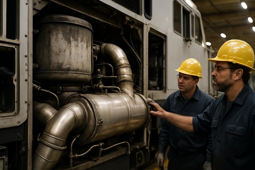
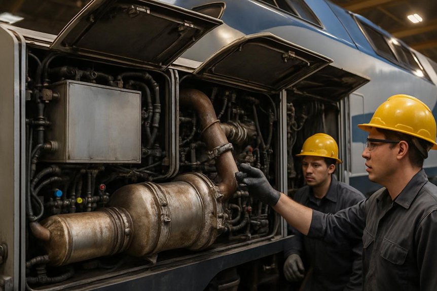
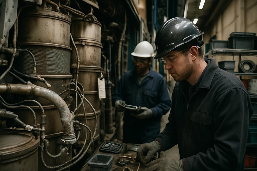
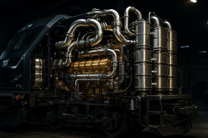
What Makes the EMD F125 Aftertreatment System Truly Fantastic

What Makes the EMD F125 Aftertreatment System Truly Fantastic

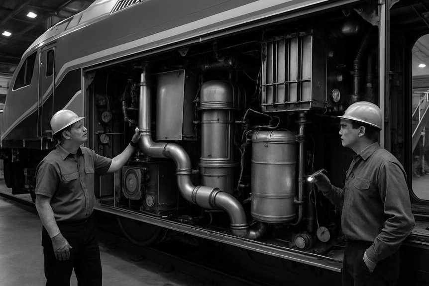
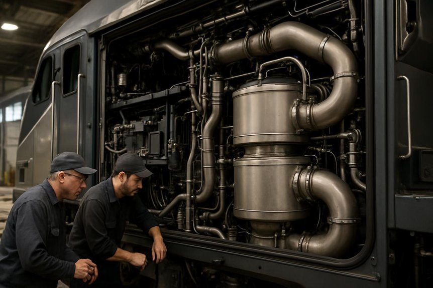
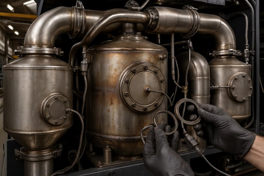
The EMD F125 aftertreatment system combines multiple components to meet stringent Tier 4 emissions for passenger locomotives. You’ll find the EMD F125 uses a Tier 4 aftertreatment package with a DOC, DPF, and SCR/DEF system. You inspect the DOC during scheduled A/B services, monitor DPF differential pressure and regeneration behavior, and plan ash cleaning around roughly 250,000–400,000 miles equivalent or engine-hour limits. Common failures include DOC poisoning or cracking, DPF plugging, sensor faults, DEF crystallization, injector coking, frozen lines, and SCR catalyst degradation. Next, you’ll see how each system affects reliability.

What aftertreatment components (e.g., SCR, DPF) are used on the EMD F125, and what are their maintenance intervals and failure modes?

The EMD F125 aftertreatment system combines multiple components to meet stringent Tier 4 emissions for passenger locomotives. It typically integrates a diesel oxidation catalyst, diesel particulate filter, and selective catalytic reduction catalyst in a compact module. Together, these units reduce particulate matter, hydrocarbons, carbon monoxide, and NOx while maintaining high power output.

Maintenance intervals are driven by duty cycle, fuel quality, and lube oil control. DPF ash cleaning often occurs between 250,000 and 400,000 miles equivalent, or at defined engine‑hour triggers. SCR systems require regular DEF quality checks, filter replacement, nozzle inspection, and sensor calibration during scheduled locomotive overhauls.

Typical failure modes include DPF plugging from excess soot or ash, cracked substrates, and failed differential pressure sensors. SCR issues include DEF crystallization, injector coking, degraded catalyst, NOx sensor drift, and wiring faults. These failures can cause derates, increased fuel consumption, higher emissions, and nuisance alarms for operators.

Key Takeaways

  • The EMD F125 aftertreatment system includes a DOC, DPF, SCR catalyst, DEF dosing hardware, mixer, sensors, and exhaust monitoring controls.
  • The DOC oxidizes CO and hydrocarbons, supports DPF regeneration, and should be inspected during A- or B-level services.
  • DPF maintenance is driven by pressure trends, regeneration behavior, and ash cleaning typically planned around 250,000–400,000 miles equivalent.
  • SCR maintenance focuses on clean DEF, filtration, nozzle checks, accurate sensors, and proper catalyst function for NOx conversion.
  • Common failures include DOC poisoning, DPF plugging or cracking, DEF contamination, injector issues, sensor faults, and SCR catalyst degradation.

Understanding the EMD F125 Aftertreatment System

Understanding the EMD F125 Aftertreatment System

You need to understand how the EMD F125 aftertreatment system supports EPA Tier 4 emissions compliance in passenger service. You’ll see how the DOC, DPF, and SCR work together to control hydrocarbons, soot, and NOx. Then, you’ll trace the exhaust flow path and see why each stage affects reliability and maintenance planning.

Tier 4 Regulations Driving the F125 Design

Tier 4 emissions rules shaped every major design choice in the EMD F125 aftertreatment system. You face limits on locomotive NOx and particulate matter that legacy EMD platforms couldn’t meet through combustion changes alone. That’s why the F125 needed an integrated emissions strategy, not a bolt-on approach.

You also manage passenger-rail duty cycles that differ sharply from freight service. Frequent starts, station stops, rapid loading, and extended idle periods create unstable exhaust temperatures. Those conditions challenge soot control and NOx reduction while you still need dependable schedule performance.

For emd f125 emissions compliance and reliability, the design had to balance high power, low emissions, and maintainable packaging. Tier 4 pushed the F125 toward coordinated exhaust treatment, engine calibration, and controls built for commuter railroad realities, not long-haul freight assumptions.

Core Components: DOC, DPF, and SCR Overview

While the packaging is compact, the EMD F125 aftertreatment system relies on three distinct emissions-control stages. You first look at the diesel oxidation catalyst, or DOC, which oxidizes carbon monoxide and unburned hydrocarbons. That matters because cleaner exhaust chemistry supports downstream catalyst performance and Tier 4 compliance.

Next, you manage the diesel particulate filter, or DPF. It captures soot and stores noncombustible ash from locomotive fuel and lube oil. Sustained passenger duty can keep exhaust temperatures high, but ash still accumulates.

Finally, selective catalytic reduction reduces NOx using DEF and catalyst reactions. On a passenger locomotive, these components sit in a dense rooftop or carbody package. You must consider heat rejection, vibration, access, and sensor durability when evaluating emd f125 aftertreatment system reliability.

Exhaust Flow Path on the EMD F125

After identifying the DOCDPF, and SCR, the next step is tracing the exhaust path. In the EMD F125 aftertreatment system, exhaust leaves the turbo outlet and enters the DOC first. You use this stage to oxidize hydrocarbons and carbon monoxide, while raising temperatures for downstream filtration.

Next, gases pass through the DPF, where the substrate captures soot before it reaches the SCR section. The exhaust flow path on the emd f125 then moves into a mixing section. Here, the DEF injector doses urea, and controlled turbulence helps distribute ammonia evenly.

Temperature sensors, pressure sensors, and engine controls monitor each stage. They protect catalyst efficiency and prevent poor dosing. Finally, gases pass through the SCR catalyst, reduce NOx, and exit through the locomotive stack.

Diesel Oxidation Catalyst (DOC) on the F125

Diesel Oxidation Catalyst (DOC) on the F125

You’ll find the DOC at the front of the EMD F125 aftertreatment system, where it oxidizes hydrocarbons and carbon monoxide. You need clear inspection intervals because soot, oil ash, and thermal stress can reduce catalyst performance. When the DOC plugs, cracks, or loses activity, you risk derates, higher emissions, and costly downtime.

Role of the DOC in Locomotive Emissions Control

Convert carbon monoxide and unburned hydrocarbons early, and the DOC protects the rest of the EMD F125 aftertreatment system. You use this catalyst to oxidize CO into CO2 and burn hydrocarbons left after combustion. That cleaner exhaust reduces odor, visible smoke, and catalyst contamination downstream.

The DOC also supports DPF regeneration. As exhaust passes through, oxidation reactions raise temperature, helping burn soot when locomotive duty cycles allow it. That heat matters in commuter service, where variable load cycles and long idling can keep exhaust temperatures low. You can’t treat the DOC as a standalone part. Its performance affects diesel particulate filter maintenance for passenger locomotives, SCR efficiency, and emissions reliability. When DOC conversion drops, soot loading rises, regeneration weakens, and downtime risk increases quickly for your fleet.

DOC Maintenance Intervals and Inspection Practices

Typically, you should align DOC inspections with A- or B-level locomotive services, depending on fleet duty cycle and OEM guidance. For the EMD F125 aftertreatment system, you’ll usually confirm housing integrity, mounting security, and exhaust joint condition during scheduled service.

You should look for external damage, soot staining, loose insulation, and signs of thermal cracking. Check temperature trends across the DOC, then compare them with historical data. Use exhaust back-pressure readings to infer restriction before it affects downstream DPF loading or selective catalytic reduction on tier 4 locomotives.

Don’t rely only on visual checks. Review event logs, sensor trends, and recent regeneration behavior. If data shifts unexpectedly, escalate inspection before the next interval. This approach helps you protect emissions compliance, reduce downtime, and plan parts support with confidence.

Common DOC Failure Modes and Their Impact

failing DOC rarely stays isolated for long on an F125. You’ll see its impact across the EMD F125 aftertreatment system, especially upstream of DPF regeneration. Sulfur, lube ash, coolant, or fuel contaminants can poison the catalyst washcoat. That reduces oxidation efficiency and leaves more hydrocarbons for downstream components.

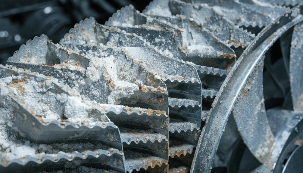
Face plugging raises exhaust back pressure and can trigger fuel penalties during commuter duty. Thermal sintering from excessive exhaust temperatures reduces active surface area. Cracked substrates can shed material, disturb flow, and accelerate DPF loading.

You may notice poor passive regeneration, rising differential pressure, nuisance alarms, or emissions exceedances. Don’t treat those symptoms as sensor noise. Verify fuel and lube quality, inspect exhaust leaks, review temperature history, and borescope the DOC before condemning downstream SCR or DPF hardware.

Diesel Particulate Filter (DPF) on the F125

Diesel Particulate Filter (DPF) on the F125

You rely on the DPF to capture soot while ash slowly accumulates in passenger service. You’ll plan cleaning around duty cycle, fuel quality, lube oil control, and pressure trends. You can spot issues early through rising backpressure, frequent regeneration faults, derates, or differential pressure sensor alerts.

How the DPF Handles Soot and Ash in Passenger Service

In passenger service, the F125 DPF traps soot in its porous filter walls while non-combustible ash builds slowly. You rely on the EMD F125 aftertreatment system to burn soot when exhaust temperature supports regeneration.

ConditionDPF responseYour operational cue
Fast commuter runPassive regeneration oxidizes sootStable backpressure
Long idleSoot accumulates fasterWatch differential pressure
Stop-start dutyTemperatures fluctuateMore soot loading risk
High oil carryoverAsh risesReduced filter capacity

Passive regeneration works best on sustained high-speed segments, where heat stays consistent. Active regeneration adds heat when controls detect soot loading above limits. You shouldn’t confuse soot with ash. Soot can burn off, but ash remains from lube additives and engine wear. That difference matters for EMD F125 emissions compliance and reliability.

DPF Cleaning Intervals and Service Planning

Typically, F125 fleets plan DPF ash cleaning around 250,000 to 400,000 miles equivalent, or matched engine-hour limits. You should treat that range as a planning baseline, not a guarantee. The EMD F125 aftertreatment system responds differently across commuter duty cycles, idle time, fuel quality, and oil consumption.

You’ll get better results by tracking DPF differential pressure trends during inspections. Rising pressure drop helps you schedule cleaning before availability suffers. Build service plans around module removal, certified cleaning, inspection, return shipping, and reinstallation windows. These DPF modules are large, so logistics matter as much as shop labor.

For diesel particulate filter maintenance for passenger locomotives, align cleaning with major inspections when possible. You’ll reduce repeat downtime, control spare-module needs, and support EMD F125 emissions compliance and reliability.

DPF Failure Modes and Diagnostic Clues

When DPF problems develop on the F125, they usually show up as airflow, temperature, or pressure abnormalities. You’ll often see the EMD F125 aftertreatment system report rising differential pressure, especially under load. That points to soot or ash plugging, restricted channels, or failed pressure sensing.

You may also see frequent regen commandslonger regen events, or incomplete regeneration. If regeneration runs uncontrolled, excessive heat can melt the substrate. Channel cracking can follow thermal shock, vibration, or uneven soot loading. Gasket leaks create bypass paths, reducing filtration and confusing sensor readings.

Watch for smoke at the stack, aftertreatment fault codes, and power derates. Don’t treat these as nuisance alarms. They protect emissions compliance, fuel economy, and service availability in passenger locomotive duty.

SCR and DEF System on the EMD F125

SCR and DEF System on the EMD F125

You manage SCR chemistry by dosing DEF into hot exhaust before the catalyst reduces NOx to nitrogen and water. You’ll need clean DEF, sound filtration, accurate sensors, and scheduled nozzle checks to protect emissions compliance. When crystallization, injector coking, NOx sensor drift, or catalyst damage appears, you can face alarms, derates, and downtime.

SCR Chemistry and Layout on Tier 4 Locomotives

Although SCR chemistry is straightforward in principle, the locomotive application demands careful control. In the EMD F125 aftertreatment system, you inject DEF into hot exhaust, where it decomposes into ammonia. That ammonia reacts over SCR catalyst bricks, converting NOx into nitrogen and water.

  • You need uniform DEF spray before the catalyst face.
  • The injector sits upstream of a mixer for evaporation.
  • The mixer promotes ammonia distribution across high exhaust flow.
  • Catalyst bricks sit downstream, sized for Tier 4 duty.
  • Sensors verify temperature, NOx conversion, and control response.

Because locomotive exhaust paths are long and high-volume, layout matters. Poor mixing creates ammonia slip, deposits, or low NOx conversion. You protect reliability by watching temperature control, dosing accuracy, and catalyst efficiency trends.

DEF Handling, Filtration, and Service Intervals

Because SCR performance depends on clean DEF, your F125 service program should treat DEF as a controlled fluid. For the EMD F125 aftertreatment system, verify DEF concentration, cleanliness, and storage age before filling. Use sealed transfer equipmentdedicated containers, and depot dispensing filters to prevent dust, oil, coolant, or fuel contamination.

You should inspect DEF tanks for sediment, damaged caps, blocked vents, and heater operation during scheduled service. Replace DEF filters at OEM-defined intervals, commonly aligned with periodic locomotive inspections or annual service. In cold yards, confirm tank heaters, heated lines, and thaw logic work before winter service. Purge or drain exposed lines when locomotives sit in freezing conditions. Keep fill points clean, label DEF-only tools, and document batch numbers for traceability.

SCR and DEF Failure Modes in Rail Operation

Clean DEF handling reduces risk, but SCR reliability still depends on heat control, dosing accuracy, and sensor feedback. In the EMD F125 aftertreatment system, small SCR faults can quickly affect locomotive availability and compliance.

  • You’ll see injector coking when heat bakes DEF residue onto the dosing nozzle.
  • You can get DEF crystallization after shutdowns, leaks, or poor purge performance.
  • Frozen DEF lines may block dosing during cold starts or winter layovers.
  • Catalyst degradation reduces NOx conversion and raises emissions fault frequency.
  • NOx sensor driftlevel sensor failures, or wiring faults can mislead controls.

When the control system can’t verify NOx reduction, it may log faults, limit speed, or enforce derates under Tier 4 rules. You reduce risk with inspections, sensor checks, and disciplined troubleshooting.

Reliability, Procurement, and Best Practices for F125 Fleets

Reliability, Procurement, and Best Practices for F125 Fleets

You can protect the EMD F125 aftertreatment system by tracking sensor trends, fault codes, and DPF pressure data. You’ll reduce downtime when you align spares, warranties, and vendor support before failures occur. You extend DOC, DPF, and SCR life through clean DEF handling, proper fuel quality, and stable operating practices.

Data‑Driven Maintenance and Condition Monitoring

data-driven maintenance program helps F125 fleets shift from fixed intervals to condition-based decisions. You can protect the EMD F125 aftertreatment system by trending exhaust back-pressure, temperature, and NOx sensor data.

  • Track DPF differential pressure to spot soot loading before derates occur.
  • Compare inlet and outlet temperatures across DOC, DPF, and SCR sections.
  • Monitor NOx conversion efficiency to confirm selective catalytic reduction performance.
  • Use onboard diagnostics with remote monitoring to prioritize locomotive shop visits.
  • Review fault-code history against duty cycle, fuel quality, and lube consumption.

You’ll reduce unnecessary inspections when readings stay stable. You’ll also catch sensor drift, DEF dosing issues, or rising restriction earlier. That gives rail engineers clearer maintenance triggers and helps procurement specialists plan service without guessing.

Spares, Warranties, and Vendor Coordination

Effective spares planning protects F125 availability when aftertreatment faults appear between scheduled shop windows. You should stock DPF cartridgesdifferential pressure sensorsNOx sensors, temperature sensors, DEF pumps, filters, injectors, and dosing lines by failure criticality. For the EMD F125 aftertreatment system, sensor gaps often cause faster service impacts than catalyst failures.

Align stock levels with lead times, fleet size, warranty coverage, and overhaul cadence. You’ll reduce risk when you document approved DPF cleaning vendors, cleaning limits, and inspection records. Warranty terms may require OEM-approved parts, calibrated sensors, and traceable service history. Aftermarket options can lower cost, but you must verify emissions compliance, fit, materials, and support. Mikura International helps you coordinate qualified parts sourcing, documentation, and vendor communication without compromising reliability.

Operational Practices to Extend Aftertreatment Life

Parts planning protects availability, but daily operating discipline protects component life. You extend the EMD F125 aftertreatment system by controlling heat, soot, ash, and contamination.

  • Load the engine enough to maintain exhaust temperature and support passive regeneration.
  • Minimize unnecessary idling, since cool exhaust accelerates DPF soot loading and SCR deposits.
  • Use specified ultra-low-sulfur fuel, and verify suppliers meet locomotive fuel cleanliness requirements.
  • Choose approved low-ash lube oil, because excess ash shortens diesel particulate filter maintenance intervals.
  • Train crews and technicians to act quickly on DEF, NOx, temperature, and differential-pressure alarms.

You can’t eliminate every fault, especially in commuter duty cycles. Still, consistent operating discipline reduces plugging, regen issues, nuisance derates, and unscheduled downtime. Mikura International supports that discipline with dependable parts planning and technical guidance.

Frequently Asked Questions

How Does Altitude Affect EMD F125 Aftertreatment Performance?

Altitude lowers air density, so you get less oxygen for combustion and hotter exhaust management challenges. On the EMD F125 aftertreatment system, that can increase soot loading, affect DPF regeneration, and change SCR NOx conversion efficiency. You’ll need calibration that accounts for elevation, clean sensors, proper DEF dosing, and verified turbocharger performance. Don’t ignore altitude-related derates; they protect catalysts, control emissions, and prevent costly passenger locomotive downtime in service.

Can Aftertreatment Faults Affect Passenger Train Schedule Recovery?

Yes, aftertreatment faults can directly hurt schedule recovery. You may lose horsepower when the EMD F125 aftertreatment system triggers derates from DPF restriction, SCR faults, DEF issues, or sensor failures. That slows acceleration after station stops and limits recovery margins. You’ll also face alarms, troubleshooting delays, or locomotive swaps. To protect schedules, you should trend pressures, NOx data, DEF quality, and fault codes before issues become service disruptions.

What Data Should Procurement Teams Request From Aftertreatment Suppliers?

Ask suppliers for lifecycle data that separates wheat from chaff. You’ll want EMD F125 aftertreatment system duty-cycle assumptionsDPF ash capacity, cleaning intervals, SCR conversion efficiency, DEF consumption, sensor calibration limits, fault-code logic, warranty exclusions, and documented failure rates. Request locomotive-specific test evidence, not generic engine claims. You should also ask for lead times, rebuild options, core policies, technical support scope, and parts traceability to protect uptime and budgets.

How Should Stored F125 Locomotives Protect Aftertreatment Components?

You should protect stored F125 locomotives by keeping exhaust paths sealedDEF drained or stabilized, and batteries maintained for controls. Don’t let moisture enter DOC, DPF, or SCR housings. Run approved periodic start-ups only when exhaust temperatures reach regeneration thresholds. Inspect NOx sensors, pressure lines, and wiring before return to service. You’ll reduce crystallization, corrosion, substrate cracking, and nuisance derates by following OEM storage procedures and documenting conditions.

Are Remanufactured Sensors Suitable for EMD F125 Emissions Systems?

Yes, you can use remanufactured sensors on the EMD F125 aftertreatment system if they meet OEM calibration, response-time, and durability requirements. You shouldn’t treat NOx, temperature, or differential-pressure sensors as generic parts. Validate serial traceability, bench-test results, connector integrity, and warranty coverage before installation. Poor reman quality can trigger false faults, DEF dosing errors, DPF regeneration issues, derates, and emissions noncompliance. Mikura International helps you source reliable, tested locomotive sensor solutions.

How the EMD F125 Tier 4 Locomotive Makes Spectacular, Better Clean Power

How the EMD F125 Tier 4 Locomotive Makes Spectacular, Better Clean Power

You support Tier 4 on the EMD F125 by treating the Caterpillar C175-20 as part of an integrated emissions system, not a detuned engine. Its high-output V20 architecture, electronic injection, advanced turbocharging, and ECU controls keep combustion stable while preserving roughly 4,700 hp. Downstream SCR, oxidation catalyst, particulate control, DEF dosing, cooling, and diagnostics cut NOx and PM without heavy derating. The full system explains how power, compliance, and availability stay aligned.

How does the EMD F125’s prime mover architecture support Tier 4 emissions without compromising power output?

The EMD F125 uses a Caterpillar C175-20 prime mover with a modern aftertreatment chain. This architecture delivers Tier 4 compliance while still providing around 4,700 hp for demanding passenger duty cycles. Instead of detuning the engine, EMD and Caterpillar manage emissions downstream and through precise controls.

The C175-20 employs electronic fuel injection, advanced turbocharging, and high-pressure combustion management. These keep cylinder efficiency high while minimizing in-cylinder NOx and particulates. An integrated aftertreatment system then handles remaining pollutants using components like selective catalytic reduction (SCR) and diesel oxidation catalysts. This allows the engine to stay in an efficient power band even under 125 mph, 10-car commuter loads.

For rail engineers and procurement teams, the key benefit is balancing regulatory compliance, performance, and lifecycle cost. The F125’s architecture preserves tractive performance and head-end power capability, while meeting strict EPA Tier 4 limits on NOx and PM for modern passenger corridors.

Key Takeaways

  • The Caterpillar C175-20 V20 provides about 4,700 hp while leaving packaging space for cooling and emissions hardware.
  • Electronic fuel injection precisely controls timing and quantity, reducing soot and NOx without sacrificing throttle response.
  • Advanced turbocharging maintains air mass under load, supporting clean combustion and full passenger power demand.
  • Integrated SCR, DOC, and particulate controls treat exhaust downstream, allowing the engine to avoid heavy derating.
  • ECU monitoring coordinates combustion, HEP load, sensors, and aftertreatment to preserve reliability and Tier 4 compliance.

Understanding the EMD F125 Tier 4 Locomotive

emd f125 tier 4 4 700hp

You’ll find the EMD F125 Tier 4 locomotive positioned for high-speed commuter fleets needing clean emissions and full passenger performance. You need Tier 4 compliance to reduce NOx and PM through coordinated engine controls and aftertreatment. The Caterpillar C175-20 prime mover architecture supports 4,700 hp, HEP demand, and 125 mph service without planned derating.

Where the F125 Fits in Modern Passenger Fleets

You can configure it for typical 8- to 10-coach consists, with capacity aligned to peak commuter demand. It also gives you a practical replacement path for aging F59 and F40 series units without abandoning diesel infrastructure. In fleet planning, you’re not just swapping locomotives. You’re upgrading propulsion, emissions control, HEP capability, and service reliability within a modern passenger platform built for today’s regulatory and operating pressures.

What Tier 4 Emissions Mean for Locomotives

While older passenger locomotives relied on mechanical tuning, an EMD F125 Tier 4 locomotive must meet strict EPA limits for nitrogen oxides and particulate matter. You’re managing emissions targets built for line-haul and passenger rail duty, not highway engines.

  • Tier 4 cuts NOx through controlled combustion and downstream treatment.
  • PM limits demand cleaner fuel burn and particulate control.
  • Electronic injection replaces simple rack-based mechanical fueling.
  • Advanced air handling keeps combustion stable across load changes.
  • A locomotive tier 4 aftertreatment system treats exhaust after cylinders do their work.

For passenger diesel locomotive emissions, you can’t depend on detuning alone. OEMs must coordinate in-cylinder controls with exhaust chemistry. That systems approach lets you meet compliance while preserving the operating envelope rail corridors require. Mikura International understands these constraints when supporting modern fleets.

Design Goals Behind the F125’s Prime Mover Architecture

Because commuter rail leaves little margin for lost power, the EMD F125 Tier 4 locomotive was designed to protect performance first. You need roughly 4,700 hp at the alternator, strong acceleration, and dependable schedule recovery, even while meeting strict NOx and PM limits.

The design goal isn’t simple compliance. It’s system balance. The emd f125 tier 4 locomotive must feed traction motors, support high head-end power loads, cool the prime mover and aftertreatment, and still fit within a passenger locomotive envelope. That means high power density, coordinated controls, and emissions equipment that doesn’t force engine derating.

For rail engineers and procurement teams, this architecture matters because it preserves capacity where service demands it most: acceleration, hotel power, reliability, and regulatory compliance in daily corridor operation.

Inside the Caterpillar C175-20 Prime Mover

20 cylinder tier 4 prime mover

You’ll see the EMD F125 Tier 4 locomotive build performance around the Caterpillar C175-20 prime mover’s 20-cylinder architecture. You manage emissions through precise fuel injection, advanced turbocharging, and controlled combustion before exhaust reaches aftertreatment. You also rely on rail-duty engine controls to balance traction power, HEP demand, cooling, and diagnostic visibility.

Core Architecture of the C175-20 Engine

Although Tier 4 compliance depends heavily on downstream controls, the EMD F125 Tier 4 locomotive starts with a capable core engine. You work from the caterpillar c175-20 prime mover, a V20, four-stroke, high-speed diesel built for rail duty and heavy industrial loading.

  • You get high brake mean effective pressure, so each cylinder delivers strong power density.
  • You fit substantial output inside a passenger locomotive carbody without excessive mass.
  • You rely on compact packaging that leaves room for cooling and emissions hardware.
  • You benefit from modular construction, which supports service access and component planning.
  • You maintain a robust mechanical platform before the locomotive Tier 4 aftertreatment system treats exhaust.

This core architecture helps protect horsepower, reliability, and passenger diesel locomotive emissions compliance.

Fuel Injection, Turbocharging, and Combustion Strategy

When the train leaves a station, the Caterpillar C175-20 prime mover must add power quickly without overfueling. You get that balance through electronically controlled fuel injection, optimized timing, and advanced turbocharging. The injection system meters fuel precisely, so each cylinder receives the right quantity at the right crank angle. That improves heat release, limits smoke, and reduces raw particulate output.

Turbocharging keeps air mass available as load rises, supporting fast transient response during commuter acceleration. You maintain cylinder efficiency without pushing excess fuel into a weak air charge. In an emd f125 tier 4 locomotive, this combustion strategy lowers engine-out NOx and PM before exhaust reaches aftertreatment. You preserve high power density, cleaner combustion, and reliable acceleration for repeated station stops while protecting lifecycle emissions performance.

Engine Controls and Monitoring for Rail Duty Cycles

Because commuter service rarely holds one steady load, the Caterpillar C175-20 relies on electronic controls. You need fast response without excess fuel, smoke, or thermal stress.

  • The ECU maps throttle changes against traction demand and HEP load.
  • It manages long idle periods to limit passenger diesel locomotive emissions.
  • Sensors track coolant, oil, exhaust, boost, and fuel pressures continuously.
  • Emissions inputs help coordinate combustion with SCR and oxidation catalyst needs.
  • Diagnostics flag drift before faults force service disruptions.

In an emd f125 tier 4 locomotive, this control layer keeps the engine in its efficient window. You don’t micromanage injection timing, air handling, or protection logic. The system adjusts them continuously, supporting 4,700 hp operation while protecting aftertreatment performance and commuter reliability.

Aftertreatment: The Heart of Tier 4 Compliance

tier 4 scr aftertreatment system

You see the EMD F125 Tier 4 locomotive meet emissions limits through a tightly integrated aftertreatment chain. You rely on SCR to cut NOx while the Caterpillar C175-20 prime mover maintains full passenger power. You also manage backpressure, heat, and space so the locomotive Tier 4 aftertreatment system supports reliability.

Components of the F125 Exhaust Aftertreatment System

The F125’s locomotive Tier 4 aftertreatment system treats emissions downstream, so the Caterpillar C175-20 prime mover doesn’t need major power derating. You get an emd f125 tier 4 locomotive architecture that protects output while controlling passenger diesel locomotive emissions.

  • Diesel oxidation catalyst converts hydrocarbons and carbon monoxide before they leave the stack.
  • Particulate-control elements reduce soot loading from high-power commuter duty cycles.
  • DEF dosing hardware meters reductant into the exhaust stream with control accuracy.
  • Mixing hardware distributes vaporized reductant evenly before catalyst contact.
  • SCR catalyst completes NOx reduction within a compact rooftop package.

You’re looking at a system-level emissions solution, not an engine compromise. By placing treatment after combustion, the F125 keeps cylinder efficiency, traction power, and HEP capability aligned with demanding service.

How SCR Enables High Power with Low NOx

When exhaust leaves the Caterpillar C175-20 prime mover, DEF injection begins the F125’s main NOx-control process. You route urea-based DEF upstream of the SCR catalyst, where heat decomposes it into ammonia. Inside the catalyst, ammonia reacts with NOx and converts it into nitrogen and water.

That downstream conversion matters because you don’t need to suppress NOx only inside the cylinders. Engineers can keep combustion temperatures higher, preserve efficient fuel burn, and maintain strong cylinder pressure. For an EMD F125 Tier 4 locomotive, that helps protect the 4,700 hp output required for passenger schedules.

You also avoid the power losses associated with heavy exhaust gas recirculation or aggressive derating. The locomotive Tier 4 aftertreatment system carries the emissions burden while the engine stays productive.

Managing Backpressure, Heat, and Space on a Passenger Locomotive

Although SCR protects engine output, it also adds backpressure, heat, and packaging pressure inside the F125 carbody. You manage those limits through system integration, not oversized hardware. In an EMD F125 Tier 4 locomotive, exhaust routing must support the Caterpillar C175-20 prime mover without restricting turbocharger response.

  • Use smooth duct transitions to reduce pressure losses.
  • Place catalysts where temperature stays effective.
  • Shield nearby wiring, hoses, and carbody structures.
  • Balance cooling airflow with passenger locomotive space limits.
  • Monitor restriction so controls protect rated horsepower.

That discipline keeps the locomotive Tier 4 aftertreatment system inside engine limits while preserving 4,700 hp capability. You’re controlling heat rejection, DEF dosing conditions, and exhaust velocity together. For passenger diesel locomotive emissions, that’s how compliance stays compatible with acceleration, HEP demand, and commuter reliability.

Power Delivery: Traction, HEP, and System Integration

integrated traction hep thermal management

You manage EMD F125 Tier 4 locomotive power as one integrated system, from alternator output to wheels and HEP loads. You coordinate AC traction, inverters, cooling, and controls so emissions compliance doesn’t compromise acceleration or passenger service. You also track thermal margins and DEF consumption because Tier 4 performance depends on balanced energy flow.

Power at the Alternator, Wheels, and Head-End Power

Trace the EMD F125 Tier 4 locomotive power chain from the Caterpillar C175-20 prime mover outward. You start with about 4,700 hp at the engine, before conversion losses reduce usable electrical power.

  • You see slightly less power at the alternator after mechanical and electrical losses.
  • You deliver roughly 4,000 hp at the wheels for traction duty.
  • You reserve capacity for head-end power, including HVAC, lighting, doors, and onboard systems.
  • You maintain acceleration because controls balance hotel loads against traction demand.
  • You support Tier 4 operation while the locomotive Tier 4 aftertreatment system manages emissions downstream.

This split matters in commuter service. You’re not trading passenger comfort for schedule reliability. Instead, the architecture keeps traction, HEP, and passenger diesel locomotive emissions aligned under real corridor loads.

AC Traction, Inverters, and Control Strategies

After the alternator splits power between traction and HEP, the EMD F125 Tier 4 locomotive depends on precise AC power conversion. You use inverter-based drives to convert generated power into controlled three-phase output for AC traction motors. That control matters because available horsepower must move trains, not create wheel slip.

Microprocessor controls monitor axle speed, load, adhesion, throttle demand, and HEP draw. They adjust inverter output in milliseconds, so each traction motor receives usable torque. You get stronger adhesion during starts, cleaner acceleration, and better tractive effort at speed.

Under Tier 4 constraints, this efficiency supports emissions compliance. The Caterpillar C175-20 prime mover can stay in productive operating ranges while controls reduce wasted fuel. For commuter service, that means responsive power delivery without unnecessary derating.

Thermal Management, Cooling, and DEF Consumption

Manage heat correctly, and the EMD F125 Tier 4 locomotive can sustain power without sacrificing emissions control. You’re cooling the Caterpillar C175-20 prime mover, traction electronics, HEP equipment, and locomotive Tier 4 aftertreatment system as one thermal network.

  • Size radiators for continuous 125 mph passenger duty, not brief peaks.
  • Control fan speed to match engine load, ambient temperature, and SCR needs.
  • Protect catalyst efficiency by holding exhaust temperatures within target windows.
  • Track DEF use against diesel burn, commonly a small percentage of fuel volume.
  • Plan DEF tank capacity around commuter cycles, layovers, and fueling windows.

You don’t just refill urea; you manage emissions availability. Onboard monitoring helps you predict DEF range, prevent inducements, and protect passenger diesel locomotive emissions compliance without derating power during demanding service.

Operational, Maintenance, and Procurement Considerations

tier 4 locomotive lifecycle readiness

You assess the EMD F125 Tier 4 locomotive by uptime, emissions stability, and service readiness. You can’t separate Caterpillar C175-20 maintenance from SCR, DEF, cooling, and controls performance. You also need lifecycle cost models that reflect fuel use, aftertreatment service, and commuter rail availability.

Reliability and Availability in Commuter Rail Service

In commuter rail service, the EMD F125 Tier 4 locomotive must protect availability under tight schedules and repeated duty cycles. You need a platform that keeps emissions hardware from becoming a service bottleneck. The Caterpillar C175-20 prime mover supports that goal through proven industrial architecture, adapted for rail loads and passenger diesel locomotive emissions limits.

  • You get modular engine and accessory layouts that support faster fault isolation.
  • You can access locomotive Tier 4 aftertreatment system modules without major teardown.
  • You reduce downtime when SCR, DOC, sensors, or dosing hardware need attention.
  • You preserve power demand for traction and HEP through integrated controls.
  • You support procurement targets by linking reliability, compliance, and lifecycle cost.

Mikura International helps you source critical parts with technical accuracy.

Maintenance Routines for Prime Mover and Aftertreatment

Reliability targets only hold when maintenance teams treat the EMD F125 Tier 4 locomotive as one integrated emissions and power system. You can’t separate Caterpillar C175-20 prime mover care from locomotive Tier 4 aftertreatment system health. Schedule engine oil and filter changes around duty-cycle severity, not mileage alone. Track injector balance, fuel spray quality, and electronic fault trends before combustion drift raises NOx or PM.

You also need disciplined SCR and catalyst inspections. Check DEF quality, storage practices, dosing injector function, and line integrity. Monitor exhaust temperature profiles across load ranges, because poor thermal control reduces conversion efficiency. When you trend these data together, you protect passenger diesel locomotive emissions compliance, preserve available horsepower, and reduce unscheduled troubleshooting during commuter service. Keep records tight for audits.

Total Cost of Ownership for Tier 4 Passenger Locomotives

Evaluate total cost of ownership by treating the EMD F125 Tier 4 locomotive as a complete power, emissions, and service platform. You’re buying more than horsepower; you’re funding compliance, uptime, and corridor access.

  • Capital cost rises with the Caterpillar C175-20 prime mover and locomotive Tier 4 aftertreatment system.
  • DEF logistics add storage, handling, training, and refilling steps to daily servicing.
  • Modern controls can improve fuel efficiency during commuter duty cycles and HEP demand.
  • Lower passenger diesel locomotive emissions reduce exposure to penalties in nonattainment regions.
  • Cleaner operation supports public acceptance in dense urban corridors.

You should model procurement, fuel, DEF, catalyst service, and availability together. At Mikura International, we help you align parts planning with emissions-critical maintenance, so compliance doesn’t become avoidable downtime.

Frequently Asked Questions

How Does Altitude Affect EMD F125 Tier 4 Locomotive Emissions Performance?

Altitude lowers air density, so you give the EMD F125 Tier 4 locomotive less oxygen for combustion and cooling. The Caterpillar C175-20 compensates through turbocharging, electronic fuel control, and aftertreatment temperature management. You’ll watch exhaust temperature, SCR efficiency, DEF dosing, and cooling margins closely. If calibration and maintenance stay correct, you maintain compliant passenger diesel locomotive emissions, though extreme altitude can reduce margin before derate or increased fuel consumption appears in service.

Can the F125 Aftertreatment System Handle Frequent Station-Stop Duty Cycles?

Yes, it can. In commuter service, you may see 20 to 30 station events per hour, so thermal stability matters. The EMD F125 Tier 4 locomotive uses SCR, oxidation catalysts, sensors, and controls to manage exhaust temperature during stop-start loading. You don’t avoid complexity, but you gain calibrated dosing, protected catalysts, and coordinated engine response. With proper DEF quality, inspections, and cooling performance, you can sustain emissions compliance.

How Is DEF Quality Monitored on the EMD F125 Tier 4 Locomotive?

You monitor DEF quality on the EMD F125 Tier 4 locomotive through onboard sensors and control logic tied to the SCR system. The system checks DEF concentration, temperature, tank level, and dosing response against expected NOx conversion. If quality drifts, you’ll see diagnostic codes or derate protections. This protects the locomotive Tier 4 aftertreatment system, keeps passenger diesel locomotive emissions compliant, and helps you plan DEF handling without service disruption.

What Diagnostics Support Troubleshooting of the Locomotive Tier 4 Aftertreatment System?

Like a control-room heartbeat, diagnostics monitor SCR efficiency, NOx sensors, DEF dosing, temperature, pressure, and catalyst performance. You use onboard fault codes, event logs, derate triggers, and trend data to isolate failures quickly. On an EMD F125 Tier 4 locomotive, these tools link the Caterpillar C175-20 prime mover, controls, and locomotive Tier 4 aftertreatment system, so you can protect passenger diesel locomotive emissions compliance without guessing during service.

How Does Cold Weather Affect SCR Performance During Commuter Rail Service?

Cold weather slows SCR catalyst light-off, so you’ll see reduced NOx conversion until exhaust temperature rises. In commuter service, frequent stops, idle periods, and short duty cycles can delay maximum performance. You manage this through calibrated engine controls, exhaust thermal management, DEF quality checks, and proper tank heating. On an EMD F125 Tier 4 locomotive, integrated monitoring helps you protect emissions compliance without sacrificing traction power or HEP reliability.

Why EMD F125 Performance Makes It the Best Commuter Locomotive Now

Why EMD F125 Performance Makes It the Best Commuter Locomotive Now

How do the EMD F125’s performance specifications (horsepower, tractive effort, top speed) translate to real-world commuter duty cycles?

The EMD F125’s 4,700 horsepower enables rapid acceleration. This is crucial for frequent station stops. It minimizes schedule delays on dense commuter lines. The engine sustains high speeds with heavy consists. This directly meets demanding duty cycles.

Its high tractive effort allows quick starts. This is vital for short station distances. The locomotive moves fully loaded trains efficiently. This reduces dwell time and improves service frequency. The AC traction system provides reliable adhesion. This ensures consistent performance in all weather.

The 125 mph top speed matches mainline track limits. This allows flexible scheduling on shared corridors. The locomotive seamlessly integrates with existing fleets. It handles peak-hour surges without overheating. These specifications translate to lower lifecycle costs. This makes it a robust commuter asset.

You translate the EMD F125’s 4,700 hp, AC traction, and 125 mph ceiling into commuter value by measuring recovery after every stop. You get stronger launches with loaded trains, tighter wheel-slip control on wet rail, and less schedule loss in peak service. The 125 mph margin helps on shared corridors where dispatch slots are tight. You also track fuel burn, cooling, emissions, diagnostics, and maintenance intervals. Next, you’ll see how those specs perform in real duty cycles.

Key Takeaways

  • The F125’s 4,700 hp supports fast acceleration and schedule recovery after frequent commuter station stops.
  • AC traction converts horsepower into controlled tractive effort, improving adhesion on wet rail, grades, and heavy peak loads.
  • Repeated stop-start duty cycles heavily load the engine, alternator, inverters, traction motors, cooling systems, and emissions equipment.
  • Tier 4 emissions systems are integrated with thermal management to maintain performance without major power derating during high-load service.
  • The 125 mph capability provides dispatch flexibility on shared corridors, though it mainly matters where station spacing and signaling allow.

Understanding the F125’s Power-to-Weight Ratio

Understanding the F125’s Power-to-Weight Ratio

When you assess EMD F125 performance specifications, the 4,700 HP rating shows its acceleration advantage between tight station stops. You get Tier 4 emissions compliance without giving up the power needed for heavy commuter consists. In peak-hour duty cycles, that power-to-weight balance supports fast starts, stable speeds, and better fleet availability.

The 4,700 HP Advantage for Rapid Acceleration

Because commuter locomotive duty cycles punish slow recovery, 4,700 horsepower matters immediately after every station stop. You’re fighting inertia, passenger load, grade, and timetable pressure at once. Within the emd f125 performance specifications, that output lets the prime mover feed the traction system with enough power to bring a heavy consist back to track speed quickly.

  1. You reduce lost seconds after each stop, protecting tight peak-period schedules.
  2. Support shorter station spacing without letting acceleration gaps compound downstream.
  3. You maintain stronger performance with full cars, where lower-powered locomotives recover more slowly.

For rail engineers and procurement teams, this isn’t just a headline rating. It’s usable recovery power. You convert horsepower into schedule resilience, better fleet utilization, and fewer delay minutes across daily service.

Meeting Tier 4 Emissions Without Sacrificing Power

Rapid acceleration only creates value if the locomotive can sustain it within modern emissions limits. With the F125, you get a high-speed diesel engine paired with exhaust after-treatment, so EPA Tier 4 compliance doesn’t force a power penalty. That matters when EMD F125 performance specifications must support commuter locomotive duty cycles, not just test-stand numbers.

System factorOperational value
High-speed dieselMaintains 4,700 hp output
After-treatmentControls NOx and particulates
Power-to-weight balancePreserves acceleration response
Thermal managementSupports repeated load changes

You’re managing emissions hardware, airflow, cooling, and traction demand as one system. The result is cleaner power delivery that still supports fast starts, sustained speed, and dependable fleet availability without compromising schedule-critical performance.

Duty Cycle Analysis for Peak-Hour Demands

Although peak-hour service looks routine on a timetable, it pushes the F125 through repeated full-power starts. You’re converting 4,700 horsepower into acceleration, then asking the locomotive to recover thermally before the next stop.

  1. Full-power launches: You load the prime mover, alternator, inverters, and traction motors hard.
  2. Thermal recovery: Cooling circuits and engine management software control temperatures, preventing overheating and power derating.
  3. Consist control: AC traction system efficiency helps you maintain adhesion while moving loaded commuter trains quickly.

That matters because EMD F125 performance specifications aren’t just brochure figures. You need dependable acceleration when platforms are crowded and dwell times compress. During peak cycles, the power-to-weight ratio supports schedule recovery without abusing components. For agencies, that protects fleet availability, maintenance planning, and locomotive lifecycle costs.

Maximizing Tractive Effort for Frequent Stops

Maximizing Tractive Effort for Frequent Stops

You use the EMD F125 performance specifications to convert AC traction efficiency into stronger adhesion at every start and cut dwell time because faster train launches restore schedule margin between closely spaced stations. You also maintain tractive effort on gradients, wet rail, and peak-load conditions without overstressing the traction system.

How AC Traction Motors Deliver Superior Adhesion

When frequent stops challenge adhesion, the F125’s AC traction system helps convert horsepower into controlled tractive effort. You gain finer wheel-slip control than older DC motor technology can provide, especially on wet, oily, or leaf-contaminated rail.

  1. AC traction system efficiency: You regulate torque at each axle, so power reaches the rail without excessive slip.
  2. Usable tractive effort: You protect adhesion margins during demanding commuter locomotive duty cycles and heavy peak loads.
  3. Lower locomotive lifecycle costs: You reduce wheel wear, thermal stress, and avoidable maintenance events.

For rail engineers evaluating EMD F125 performance specifications, this systems advantage matters. You’re not just buying rated horsepower. You’re applying it through traction electronics that stabilize adhesion, preserve components, and support repeatable performance across daily commuter service.

Reducing Dwell Time Through Faster Train Starts

AC traction converts adhesion control into faster, repeatable station starts. You use the EMD F125 performance specifications to turn high starting tractive effort into measurable timetable recovery. When doors close, the locomotive can load traction quickly, move a fully occupied consist, and reach the next speed band sooner. That first acceleration phase matters most on commuter locomotive duty cycles with short station spacing.

Each faster launch cuts seconds from platform-to-platform running time. Across dozens of stops, those seconds become schedule margin, better slot adherence, and fewer cascading delays. You also reduce throttle hunting because the AC traction system efficiency supports controlled torque delivery. For procurement teams, this links performance directly to service frequency, fleet utilization, and locomotive lifecycle costs without adding trainsets or changing the timetable structure.

Performance on Gradients and in Adverse Conditions

As gradients tighten and weather degrades adhesion, the EMD F125 performance specifications become operational safeguards. You need tractive effort that protects schedules, not just impressive catalog numbers. On routes with tunnels, bridges, and short station spacing, the F125’s AC traction system helps convert power into controlled rail adhesion.

  1. You start fully loaded trains on grades with reduced wheel slip risk.
  2. Recover speed faster after stops, protecting commuter locomotive duty cycles.
  3. You reduce traction stress, supporting fleet availability and locomotive lifecycle costs.

When rain, leaves, or cold rail reduce adhesion, consistent torque control matters. The F125 helps you maintain acceleration without excessive sanding or delay. For agencies managing peak-hour pressure, that means fewer missed slots, steadier headways, and better asset utilization under real corridor constraints.

The 125 mph Top Speed and Schedule Flexibility

The 125 mph Top Speed and Schedule Flexibility

You can use the EMD F125 performance specifications to align 125 mph capability with high-speed mainline traffic. You won’t use that speed on every commuter segment, but it protects schedule recovery on shared corridors. Aerodynamics and lightweight design help sustain speed efficiently while supporting commuter locomotive duty cycles.

Integrating with High-Speed Mainline Traffic

When commuter routes share mainline territory, top speed becomes a dispatching tool. With the EMD F125 performance specifications, you can plan around 125 mph capability instead of treating commuter trains as moving constraints. That matters when your slots sit between higher-speed intercity moves or priority freight paths.

  1. You reduce bottlenecks by matching authorized mainline speeds where signaling and track allow.
  2. Protect meets and passes because the F125 can clear control points faster.
  3. You improve network fluidity by keeping commuter consists closer to mainline traffic profiles.

For rail engineers, that speed margin supports tighter dispatch plans without relying on unrealistic recovery time. For procurement teams, it strengthens fleet utility on shared corridors, where schedule integration directly affects commuter locomotive duty cycles and locomotive lifecycle costs.

Balancing Speed Potential with Commuter Route Realities

Mainline capability only creates value if it fits real commuter stopping patterns. You rarely use 125 mph between closely spaced stations, but that margin still matters. With the EMD F125 performance specifications, you gain schedule flexibility without forcing the locomotive to run continuously at its ceiling.

On shared corridors, you can recover minutes after dwell delays, meet faster mainline paths, and avoid holding conflicts. The locomotive sustains higher speeds with reserve capacity, so propulsion and cooling systems don’t operate at constant maximum stress.

That operating headroom supports commuter locomotive duty cycles by reducing thermal strain, mechanical wear, and unscheduled maintenance risk. Over time, you protect fleet availability and control locomotive lifecycle costs while maintaining dependable peak-period performance for your agency and riders each day.

The Role of Aerodynamics and Lightweight Design

Because speed margin depends on more than horsepower, the F125’s monocoque carbody plays a direct performance role. You get a streamlined, lightweight structure that reduces aerodynamic drag and train mass.

  1. At 125 mph, lower drag means the prime mover doesn’t work as hard to hold speed.
  2. With less mass, you improve acceleration between stations and protect recovery time after delays.
  3. With lower sustained load, you support fuel efficiency, emissions compliance, and locomotive lifecycle costs.

For commuter locomotive duty cycles, that matters. You need speed flexibility on shared corridors without wasting horsepower fighting resistance. The carbody helps the AC traction system efficiency translate into usable schedule margin. In EMD F125 performance specifications, aerodynamics aren’t styling. They’re a systems-level contributor to peak reliability and fleet availability.

Translating Specifications into Lifecycle Cost Savings

Translating Specifications into Lifecycle Cost Savings

You translate EMD F125 performance specifications into locomotive lifecycle costs through fuel burnmaintenance intervals, and daily availability and gain efficiency from modern engine technology, while longer service intervals keep more units ready for peak commuter locomotive duty cycles. You also reduce risk when reliability metrics confirm stable performance under repeated starts, stops, and high-load service.

Fuel Efficiency Gains from Modern Engine Technology

Across commuter locomotive duty cycles, the EMD F125 performance specifications support fuel savings through modern electronic fuel injection. You get tighter combustion control across idle, acceleration, cruise, and braking recovery changes.

  1. The system meters fuel precisely at each load point, so you don’t overfuel during station departures.
  2. It supports 4,700 horsepower output while reducing wasted fuel during variable throttle operation.
  3. It helps lower annual gallons consumed, improving locomotive lifecycle costs without reducing performance.

For rail engineers and procurement teams, that matters because commuter service rarely runs at steady state. Your trains cycle through starts, short runs, and high-demand peak periods. Electronic fuel injection adjusts faster than older mechanical systems. You cut fuel burn, support emissions compliance, and preserve the acceleration profile your schedule requires.

Extended Maintenance Intervals and Fleet Availability

When maintenance windows tighten, the EMD F125 performance specifications help protect fleet availability through durable systems design. You reduce shop visits because the locomotive’s core systems tolerate demanding commuter locomotive duty cycles. High horsepower and strong tractive effort matter beyond acceleration. They prevent sustained overload, which helps components stay within engineered operating limits.

You also gain maintenance advantages from AC traction system efficiency. AC traction motors don’t use brushes, so you eliminate brush inspection and replacement tasks. That reduces labor hours, parts consumption, and unscheduled downtime exposure. The engine design supports longer intervals between major overhauls, keeping more locomotives assigned to service.

For procurement teams, that availability improves locomotive lifecycle costs. You’re not only buying performance. You’re buying productive fleet hours and fewer maintenance-related service constraints daily.

Reliability Metrics in Daily Commuter Service

Because commuter agencies measure reliability in service miles, Mean Distance Between Failures becomes a critical procurement metric. You use MDBF to connect EMD F125 performance specifications with actual fleet availability, not brochure ratings. Higher horsepower, AC traction system efficiency, and thermal capacity support repeatable commuter locomotive duty cycles during peaks.

  1. You reduce road failures when propulsion, cooling, and controls sustain acceleration cycles.
  2. Protect schedules when predictable tractive effort supports starts in wet rail conditions.
  3. You lower locomotive lifecycle costs when fewer failures cut rescues, overtime, and spare ratios.

For procurement teams, MDBF turns performance into financial evidence. You can model parts demand, maintenance labor, and service risk with greater confidence. Mikura International supports that planning with dependable locomotive parts expertise.

Real-World Case Studies of F125 Duty Cycles

Real-World Case Studies of F125 Duty Cycles

You can benchmark EMD F125 performance specifications against Metrolink’s Southern California duty cycles. You’ll see how acceleration, adhesion, and AC traction system efficiency compare with legacy commuter locomotives. You can then apply those findings to procurement models, fleet availability targets, and locomotive lifecycle costs.

Field data gives rail engineers the clearest test of EMD F125 performance specifications. As the first major F125 adopter, Metrolink runs them through Southern California’s demanding commuter locomotive duty cycles. You see hot, arid conditions, short station spacing, and peak-period loading stress every major subsystem.

  1. Acceleration: You can validate 4,700 hp through repeated station starts, where rapid throttle response protects schedules.
  2. Adhesion: You track AC traction system efficiency during dry rail, heat, and variable grades, confirming controlled tractive effort.
  3. Availability: You measure cooling, emissions systems, and maintenance intervals under sustained stop-start service.

For procurement teams, this operating profile matters. It shows how theoretical ratings become fleet availability, controlled locomotive lifecycle costs, and reliable corridor performance without depending on ideal test conditions.

Comparing F125 Performance to Legacy Locomotives

When agencies compare EMD F125 performance specifications with legacy units like the F59PHI, the upgrade case becomes measurable. You can tie horsepower, AC traction system efficiency, and emissions output directly to commuter locomotive duty cycles. The F125’s 4,700 hp supports faster station-to-station recovery, while legacy power can lose margin under peak consists.

MetricEMD F125F59PHI
Power4,700 hp3,200 hp
Top speed125 mph110 mph
Emissions tierTier 4Tier 0/1 era

You also reduce fuel burn through modern engine controls and better adhesion management. That matters during wet rail starts, dense schedules, and shared-corridor slots. Lower emissions improve compliance, while faster acceleration protects dwell recovery. For procurement teams, those deltas shape locomotive lifecycle costs and fleet availability.

Lessons Learned for Future Commuter Locomotive Procurement

As agencies translate EMD F125 performance specifications into new RFPs, duty-cycle data now drives sharper procurement language. You don’t just ask for horsepower, tractive effort, and speed. You define how those outputs must hold up during peak commuter locomotive duty cycles.

  1. Specify telemetry that tracks acceleration, adhesion, fuel burn, emissions, and thermal margins in service.
  2. You require remote monitoring, so maintenance teams spot faults before they reduce fleet availability.
  3. You prioritize modular repairs that shorten shop time and control locomotive lifecycle costs.

This F125 experience helps you connect AC traction system efficiency to measurable uptime. It also shows why procurement should include maintainability, diagnostics, and parts access. At Mikura International, we support that systems view with reliable locomotive parts expertise.

Frequently Asked Questions

What Is the Horsepower Rating of the EMD F125 Locomotive?

The EMD F125 locomotive is rated at 4,700 horsepower. Ironically, that big number matters most in small gaps between stations. You use that output to accelerate loaded commuter consists quickly, protect schedules, and recover from delays. It also supports sustained high-speed running without overstressing systems. With AC traction system efficiency, you turn horsepower into usable adhesion, lower locomotive lifecycle costs, and stronger fleet availability during peak commuter demand.

How Does the F125 Compare to the Older EMD F59PHI?

The F125 outperforms the older F59PHI with higher horsepowerAC traction, better adhesion, and 125 mph capability. You get faster acceleration, stronger peak-period recovery, and improved control on wet rail. Its emissions-compliant prime mover also supports lower locomotive lifecycle costs. The F59PHI remains proven, but it can’t match the F125’s AC traction system efficiency, high-speed corridor flexibility, or availability advantages for demanding commuter locomotive duty cycles.

What Type of Traction Motors Does the EMD F125 Use?

The EMD F125 uses AC traction motors, paired with an AC traction system for precise adhesion control. You get stronger wheel-slip management during wet rail conditions, quicker starts, and steadier acceleration under heavy commuter loads. That matters because frequent station stops punish inefficient traction systems. With AC traction system efficiency, you can support tighter schedules, reduce thermal stress, and improve fleet availability across demanding commuter locomotive duty cycles while controlling lifecycle costs.

How Does the F125 Support Emissions Compliance for Commuter Agencies?

You can verify the theory through fuel burnduty-cycle data, and aftertreatment performance: the F125 supports emissions compliance with a Tier 4 diesel engine package. You cut NOx and particulate output while maintaining commuter locomotive duty cycles. Its AC traction system efficiency helps reduce wasted energy during acceleration. You also protect locomotive lifecycle costs, because cleaner combustion and planned maintenance support fleet availability without sacrificing peak-hour performance or schedule reliability.

What Maintenance Intervals Affect F125 Fleet Availability?

Scheduled inspections, engine oil service, filter changes, traction motor checks, and cooling system maintenance affect F125 fleet availability most. You’ll protect uptime by aligning preventive maintenance with off-peak windows and mileage-based intervals. Because the AC traction system reduces mechanical wear, you can improve reliability during commuter locomotive duty cycles. Mikura International helps you source quality locomotive parts that support planned maintenance, reduce downtime, and control locomotive lifecycle costs.

Why the New EMD F125 is Awesome for Rail

Why the New EMD F125 is Awesome for Rail

What Are the Distinguishing Design Features of the EMD F125 Compared With Earlier EMD Passenger Locomotives?

The EMD F125 introduces advanced microprocessor controls. It features enhanced diagnostic capabilities for modern fleets. This design significantly improves operational reliability and efficiency. Unlike older models, it integrates automatic data communications. These systems allow for real-time performance monitoring and analysis. The locomotive maintains strict weight and axle constraints. It delivers higher horsepower while reducing fuel consumption.

Lower emissions meet contemporary environmental regulatory standards. Crew comfort is prioritized through improved cab ergonomics. Higher crash resistance ensures superior safety protocols. Larger fuel tanks extend operational range effectively. The F125 represents a major technological leap forward. It builds upon the legacy of the F40PH. Yet it offers distinct advantages in power management. Procurement specialists value its lower lifecycle costs.

Rail engineers appreciate its modular system architecture. This design facilitates easier maintenance and upgrades. The transition from analog to digital is complete. Modern traction systems optimize energy usage dynamically. The F125 sets a new industry benchmark.

You can distinguish the EMD F125 from earlier EMD passenger locomotives by its integrated, standards-driven design. Instead of F40PH-era analog control layers, you get microprocessor propulsion control, real-time diagnostics, tighter fuel delivery, and cleaner emissions performance. You also gain modern crashworthiness, improved cab ergonomics, longer operating range, and compatibility with existing platforms, tracks, and shops. It’s built for lifecycle value, lower service risk, and fleet readiness, with more system-level contrasts ahead.

Key Takeaways

  • The EMD F125 uses modern microprocessor controls instead of legacy analog and relay-based control systems.
  • Its propulsion system improves fuel efficiency by matching engine output more precisely to traction demand.
  • The F125 meets stricter emissions expectations with cleaner combustion control and reduced NOx and particulate output.
  • It adds modern diagnostics and real-time fault reporting to improve maintenance planning and fleet uptime.
  • The locomotive preserves compatible dimensions while adding improved crashworthiness, cab ergonomics, and digital systems.

The Evolution of EMD Passenger Power

higher horsepower cleaner commuter reliability

You see the F40PH legacy in its durable diesel-electric architecture and proven commuter rail service. You also see modern standards demand cleaner emissions, smarter controls, and tighter lifecycle cost management. With EMD F125 Design Features, you get a higher-horsepower platform built for today’s North American commuter rail requirements.

Legacy of the F40PH

Although modern fleets now demand digital intelligence, the F40PH earned its place as a benchmark in North American commuter rail. You can trace its value to a diesel-electric passenger locomotive architecture built for durability, straightforward maintenance, and dependable daily service.

The F40PH gave you robust mechanical performance without excessive system complexity. Its controls, power delivery, and service access supported maintenance teams working under tight schedules. That simplicity mattered when downtime directly affected corridor capacity and fleet availability.

When you compare emd f125 design features against the F40PH, you see the baseline clearly. The older platform proved what reliability meant in passenger duty. The F125 builds from that foundation, but your reference point remains the F40PH’s decades of proven operation across demanding commuter networks and intercity routes.

Transition to Modern Standards

As emissions limits tightened and fuel costs rose, legacy EMD passenger power faced new operating constraints. You couldn’t treat an older diesel-electric passenger locomotive as only a horsepower asset anymore. You had to evaluate combustion efficiency, emissions output, controls, diagnostics, and lifecycle risk together.

Operating pressureLegacy impactModern requirement
Emissions rulesHigher exhaust outputCleaner combustion profile
Fuel costLess efficient duty cyclesOptimized energy use
Fleet uptimeLimited fault visibilityBetter diagnostics
Procurement riskAging compliance marginsSustainable lifecycle value

This reshaped EMD F125 Design Features before the model discussion begins. You see the industry moving from durable analog platforms toward integrated, standards-driven systems built for North American commuter rail obligations. For engineers, modernization became an operating necessity.

Introduction of the F125

With the F125, EMD passenger power moved from legacy reliability toward integrated digital performance. You see that shift in how the platform entered North American commuter rail: as a modern replacement option, not a disruptive rebuild. Compared with earlier EMD units, the F125 kept compatible physical dimensions for existing tracks, platforms, clearances, and shop practices.

That matters when you’re planning fleet renewal under budget and service pressure. You can modernize locomotive propulsion systems without forcing major infrastructure changes. The diesel-electric passenger locomotive preserves operational fit while adding a stronger foundation for digital controls, diagnostics, and efficient power management. For EMD F125 Design Features, this balance is central: higher capability packaged within familiar constraints, giving engineers and procurement teams a practical path from legacy fleets to modern performance.

Microprocessor Controls and Diagnostics

integrated digital architecture with redundancy

You see EMD F125 Design Features most clearly in its integrated digital architecture, replacing legacy analog control layers. You gain redundancy that improves fault isolation, protects locomotive propulsion systems, and limits service interruptions. You also get automatic data communications, so North American commuter rail teams can monitor performance faster.

Digital Architecture Integration

While legacy EMD passenger locomotives relied heavily on analog control logic, the F125 uses advanced microprocessor systems to manage performance. You see the shift in how this diesel-electric passenger locomotive coordinates engine output, traction demand, and fuel delivery across north american commuter rail duty cycles.

Legacy EMD ArchitectureEMD F125 Digital Architecture
Analog relay logicMicroprocessor-based command layers
Fixed response curvesDynamic traction power management

With the F125, you’re not just commanding horsepower; you’re managing a networked control environment. Digital controls optimize fuel injection and combustion with tighter timing, improving response under station starts and grade changes. Compared with F40PH-era systems, EMD F125 Design Features give your engineering team clearer performance control and better integration between locomotive propulsion systems and onboard monitoring.

Redundancy and Reliability

Digital control only delivers value when the system stays available under fault conditions. In the EMD F125, redundancy supports that goal across critical locomotive propulsion systems. You don’t depend on a single control path where failure can disable the diesel-electric passenger locomotive. Instead, redundant components help preserve operation when one element drops out.

Compared with earlier EMD passenger locomotives, such as the F40PH, this is a major reliability shift. Legacy systems relied more on isolated electrical and mechanical protections. The F125 applies structured microprocessor-based design to monitor faults, isolate affected functions, and keep essential systems online. For North American commuter rail, that matters. You reduce service interruptions, protect schedules, and support lifecycle value. These EMD F125 Design Features give maintenance teams clearer fault boundaries without compromising availability.

Automatic Data Communications

As microprocessor controls collect operating data, the EMD F125 turns diagnostics into a continuous fleet function. You don’t wait for a shop inspection to understand locomotive health. Real-time data transmission sends performance, fault, and subsystem status to maintenance teams while the diesel-electric passenger locomotive remains in service.

Compared with F40PH-era systems, this is a major EMD F125 Design Features upgrade. You can identify cooling, traction, emissions, or control anomalies before they become service delays. That predictive view helps reduce downtime, protect schedules, and control lifecycle costs across North American commuter rail operations.

For rail engineers, automatic data communications support faster troubleshooting and stronger diagnostic redundancy. For procurement teams, they turn locomotive propulsion systems into measurable assets, with clearer maintenance planning and better fleet availability.

Performance and Efficiency Gains

tighter fuel control efficiency

With EMD F125 Design Features, you get tighter fuel control than legacy F40PH systems. You’re using modern locomotive propulsion systems that match load demand more precisely. You also reduce emissions through cleaner combustion management and updated aftertreatment integration.

Fuel Efficiency Improvements

Several EMD F125 Design Features directly target fuel efficiency through advanced engine management and smarter power control. You move beyond the F40PH’s more conventional control logic into a diesel-electric passenger locomotive architecture that continuously manages combustion, load demand, and auxiliary power use.

In North American commuter rail service, that matters because stop-and-go duty cycles waste fuel quickly. The F125’s control systems help you match engine output to propulsion demand more precisely, reducing unnecessary fuel burn during acceleration, cruising, and station dwell periods.

You also gain lower operating costs across the fleet. For procurement teams, those savings affect lifecycle value, not just daily fuel budgets. For rail engineers, improved engine regulation supports steadier locomotive propulsion systems while maintaining required horsepower within strict passenger-service weight constraints.

Emission Reduction Technologies

The EMD F125 Design Features improve emissions performance through cleaner combustion control and tighter engine management. You get a diesel-electric passenger locomotive built to lower nitrogen oxides and particulate matter versus legacy EMD units. Compared with an F40PH-era platform, the F125 uses modern control logic to regulate fueling, air handling, and load response more precisely.

That matters in North American commuter rail, where agencies must meet strict environmental limits without replacing non-electrified infrastructure. You can cut visible exhaust, reduce particulate loading, and manage NOx output while maintaining passenger-service power demands. These emission reduction technologies also support lifecycle planning. Cleaner operation can reduce regulatory risk, improve public acceptance, and align fleet modernization with performance targets. At Mikura International, we view this as systems progress, not isolated hardware alone.

Safety and Crew Comfort Enhancements

enhanced crash safe ergonomic cab

You see EMD F125 Design Features extend beyond propulsion into higher crash resistance standards than legacy passenger units. You also get an ergonomic cab layout that reduces crew fatigue during North American commuter rail service. With larger fuel capacity, you can support longer duty cycles without compromising operational planning.

Crash Resistance Standards

As crashworthiness requirements have advanced, EMD F125 Design Features reflect a stronger safety architecture than legacy EMD passenger locomotives. You see this shift in reinforced structural zones designed to manage collision loads more effectively than older F40PH-era frames.

The F125 meets higher crashworthiness standards, aligning with modern North American commuter rail safety expectations. You’re not just evaluating horsepower or emissions; you’re judging how the diesel-electric passenger locomotive protects operating crews and passengers during impact events.

Compared with earlier EMD designs, the F125 integrates structural reinforcements as part of its overall systems architecture. That matters when procurement teams weigh lifecycle risk, regulatory compliance, and fleet modernization. At Mikura International, we recognize that safer locomotive platforms support uptime, confidence, and long-term operational resilience for demanding passenger rail networks.

Ergonomic Cab Design

While legacy cab layouts often reflected earlier operating priorities, EMD F125 Design Features place crew ergonomics at the center of safety performance. You see the shift from the F40PH era in how the cab supports sustained commuter service.

  1. Visibility: The layout improves forward sightlines, helping you monitor signals, platforms, and track conditions with less strain.
  2. Noise and vibration: Lower cab noise and reduced vibration help limit fatigue during long North American commuter rail assignments.
  3. Control placement: Ergonomic controls keep key functions within natural reach, so you can respond faster and make fewer input errors.

For rail engineers, this cab design isn’t cosmetic. It ties human factors to locomotive propulsion systems, operational precision, and safer diesel-electric passenger locomotive performance. Mikura International recognizes its maintenance impact.

Larger Fuel Capacity

The larger fuel tank is one of the practical EMD F125 Design Features that improves range without disrupting existing commuter rail operations. You gain longer service intervals between fueling events, which matters on dense North American commuter rail schedules. Compared with earlier diesel-electric passenger locomotive platforms, this capacity reduces yard movements and service interruptions.

You can plan routes with fewer fueling constraints, especially when equipment cycles through peak-period assignments. The added range also supports contingency planning when delays, detours, or terminal congestion affect normal operations. In systems terms, fuel capacity works with efficient locomotive propulsion systems, not against weight limits. You’re extending usable duty cycles while preserving compatibility with established infrastructure. For procurement teams, fewer fueling stops can support better asset utilization and lower lifecycle operating exposure over time.

Strategic Value for Procurement

lifecycle cost and fleet modernization

When you assess EMD F125 Design Features, you compare lifecycle cost against legacy F40PH maintenance profiles. You’ll also weigh fleet compatibility, since the F125 supports modernization without forcing major infrastructure changes. You future-proof procurement by selecting digital controls, cleaner propulsion, and scalable diagnostics for North American commuter rail.

Lifecycle Cost Analysis

For procurement teams, EMD F125 Design Features shift the cost discussion from purchase price to total cost of ownership. You’re comparing a modern diesel-electric passenger locomotive against older EMD platforms with higher operating exposure.

  1. Fuel efficiency: You reduce recurring fuel spend through modern propulsion management and improved energy use.
  2. Maintenance demand: You lower lifecycle burden because diagnostic systems help teams identify faults earlier.
  3. Asset value: You offset higher initial investment through reduced operational expenditures over the locomotive’s service life.

For North American commuter rail planning, this changes procurement logic. You don’t just buy horsepower; you buy predictable operating economics. Earlier models may cost less upfront, but the F125’s systems-focused design supports tighter budgets, fewer surprises, and stronger long-term fleet value.

Compatibility with Existing Fleets

Because fleet replacement rarely happens all at once, EMD F125 Design Features support phased modernization alongside older EMD passenger locomotives. You can add capacity without retiring serviceable F40PH-era assets prematurely. That matters when budgets, shop capacity, and service commitments collide.

Procurement factorEarlier EMD fleetF125 integration value
Fleet rolloutFull replacement pressuresStaged deployment
OperationsMixed consists need planningRuns alongside legacy units
TrainingAnalog habits dominateDigital systems introduced gradually
MaintenanceExisting practices remain usefulNew diagnostics layer in
Capital planningLarge upfront exposureSpend spreads over cycles

You keep North American commuter rail service stable while introducing a modern diesel-electric passenger locomotive. This compatibility reduces procurement risk and protects operational continuity during switching planning.

Future-Proofing Investments

As procurement cycles extend beyond initial delivery, EMD F125 Design Features help protect capital investments through modular architecture and software-driven adaptability. You’re not locking your fleet into fixed capability like older analog passenger units.

  1. Upgrade path: You can add future technologies through modular subsystems, reducing major teardown risk.
  2. Software leverage: You can improve propulsion logic, diagnostics, and data handling through updates, often without hardware changes.
  3. Lifecycle control: You can keep a diesel-electric passenger locomotive aligned with North American commuter rail requirements longer.

Compared with legacy EMD platforms, the F125 gives you a more adaptable asset. Its architecture supports changing emissions expectations, maintenance strategies, and performance targets. At Mikura International, we recognize how that flexibility helps procurement teams manage risk, budgets, and fleet readiness.

Frequently Asked Questions

How Does the EMD F125 Compare to the F40PH in Fuel Efficiency?

You’ll see better fuel efficiency with the EMD F125 than the F40PH because its microprocessor-controlled diesel-electric systems optimize power output in real time. Unlike the older F40PH’s less adaptive controls, the F125 manages traction, auxiliary loads, and engine performance more precisely. You reduce fuel burn, emissions, and idle waste while maintaining higher horsepower for North American commuter rail service. That efficiency supports lower lifecycle costs and fleet modernization.

What Are the Main Safety Improvements in the EMD F125 Design?

Like a signal clearing through fog, you see the F125’s safety gains in stronger crashworthiness, improved cab ergonomics, and smarter control logic. You get enhanced collision energy management, better crew visibility, and microprocessor-based monitoring that flags faults before they escalate. Compared with legacy units, it adds diagnostic redundancy and automatic data communications. You’re not just protecting equipment; you’re reducing crew risk, service disruptions, and maintenance uncertainty.

Can the EMD F125 Operate on Existing Non-Electrified Rail Lines?

Yes. You can operate the EMD F125 on existing non-electrified rail lines because it’s a diesel-electric passenger locomotive. Its onboard diesel engine drives locomotive propulsion systems without overhead catenary or third-rail power. You still use standard North American commuter rail infrastructure, subject to route clearances, axle loads, and platform compatibility. Compared with legacy units, its controls, diagnostics, and emissions systems modernize service without requiring full corridor electrification investment.

How Does the F125 Support Maintenance Planning for Aging Passenger Fleets?

Like a lighthouse in a storm, the F125 gives you clearer maintenance visibility. You track component health through microprocessor controls, onboard diagnostics, and automatic data communications. You don’t wait for failures; you plan inspections, parts staging, and service windows from real operating data. Compared with legacy analog fleets, this supports predictive maintenance, reduces unscheduled downtime, and helps you extend aging passenger fleet reliability while managing lifecycle costs.

What Infrastructure Changes Are Needed Before Deploying EMD F125 Locomotives?

You usually won’t need major infrastructure changes before deploying EMD F125 locomotives on non-electrified routes. You should verify platform clearances, axle-load limits, fueling capacity, maintenance tooling, and data communications links. Compared with older EMD passenger units, the F125 keeps compatibility with existing North American commuter rail infrastructure while adding microprocessor diagnostics. You’ll also need technician training, updated inspection procedures, and parts planning to support higher-horsepower, lower-emission locomotive propulsion systems reliably.

Translate »