

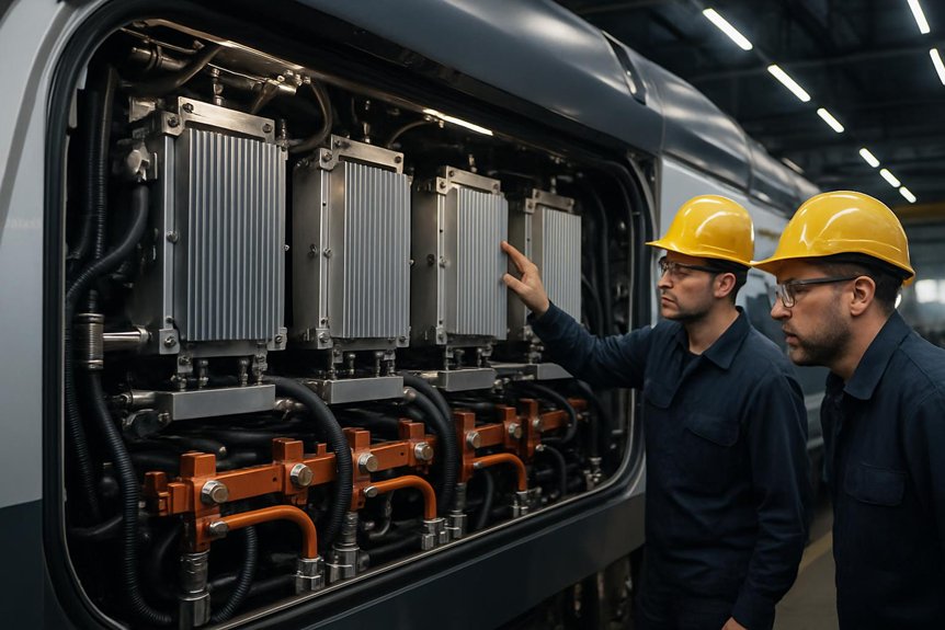
EMD F125 Traction Inverter Topology: You’ll find the EMD F125 uses a high-power voltage source inverter topology: rectified alternator output feeds a DC link, then three-leg IGBT inverter bridges create controlled three-phase AC for each traction motor. This setup improves torque control, adhesion, and regenerative braking while limiting wasted energy through optimized PWM or space-vector modulation. It also concentrates heat in managed power modules, supports liquid cooling, and enables modular fault handling. Next, you’ll see how those benefits affect lifecycle cost.
What traction inverter topology is used on the EMD F125, and how does it impact efficiency, thermal management, and reliability?
The EMD F125 uses a modern three-phase voltage source inverter topology with AC traction motors. This topology switches high DC link voltage into controlled three-phase waveforms for each traction motor. For procurement teams, understanding this choice clarifies lifecycle costs, thermal margins, and maintenance implications in high‑duty passenger service.
Efficiency is driven by semiconductor selection, PWM strategy, and DC link design. High efficiency reduces fuel burn and alternator loading for 125 mph operation. Lower switching and conduction losses translate into smaller cooling packages, lighter inverter cabinets, and more space for other locomotive systems. This directly influences total cost of ownership and energy budget planning.
Thermal management relies on liquid cooling, optimized busbar layout, and robust gate drive control. Stable junction temperatures improve reliability, extend IGBT or SiC device life, and minimize nuisance trips. Redundant protection, conservative de‑rating, and modular power stacks enhance system availability and simplify field replacement for fleet operators.
Key Takeaways
- The EMD F125 uses a DC-link-fed three-phase voltage source inverter to supply controlled AC power to each traction motor.
- Alternator AC is rectified into a high-voltage DC link, then traction inverters modulate voltage, frequency, and phase for torque control.
- IGBT-based PWM or space-vector modulation reduces torque ripple, improves adhesion control, and supports efficient part-load operation.
- Inverter efficiency depends on conduction and switching losses, affecting fuel use, DC-link stress, cooling load, and sustained high-speed performance.
- Reliability depends on liquid cooling, modular power stacks, fault protection, diagnostics, and resistance to vibration, heat, moisture, and contamination.
Understanding the EMD F125 Power Flow
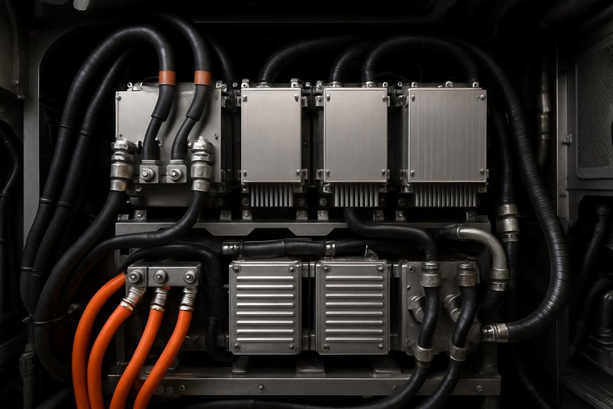
You start with the prime mover driving the alternator, which feeds a high-voltage DC link and then route that energy through traction inverters to control the AC traction motors. You also integrate a separate HEP inverter, so passenger loads stay coordinated with propulsion demand.
Prime mover, alternator, and DC link
Start with the power source: the F125’s Caterpillar prime mover drives the main alternator, which produces high-power three-phase AC for the locomotive’s electrical system. You can view this stage as the mechanical-to-electrical conversion point in the emd f125 traction inverter topology. The alternator output isn’t sent directly to the motors. Instead, rectifiers convert that AC into a controlled, stable DC link.
That DC link matters because it acts as the common electrical bus. You feed traction power from it, and you also support auxiliary inverter loads serving onboard systems. By stabilizing voltage before downstream conversion, you reduce control complexity and protect connected equipment. For rail engineers, this architecture helps separate engine speed, alternator output, and inverter demand while supporting consistent passenger-service performance under changing load conditions.
Traction inverters and AC traction motors
From the DC link, each voltage source inverter converts stable DC power into controlled three-phase AC for its traction motor. You get precise torque control because the inverter adjusts voltage, frequency, and phase in real time. This EMD F125 traction inverter topology lets each motor respond quickly to commanded tractive effort.
You also gain coordinated control across the locomotive. The traction control system compares axle speed, load, and adhesion conditions, then commands each inverter to reduce slip and maintain acceleration. At higher speeds, that same coordination supports smooth speed regulation and balanced motor loading.
For rail operators, traction inverter efficiency in locomotives matters because cleaner power conversion reduces electrical losses before energy reaches the rails. You’ll see better use of alternator output, steadier performance, and less stress on traction motors.
Separate HEP inverter and system integration
Alongside the traction inverters, the EMD F125 uses an independent 1,000 kW inverter for head-end power to the passenger consist. You keep hotel loads separate from propulsion, so lighting, HVAC, and onboard systems receive stable power during acceleration, braking, and station dwell.
| Function | Separate inverter role | Operational value |
|---|---|---|
| Traction | Feeds AC motors | Preserves propulsion control |
| HEP | Supplies consist loads | Stabilizes passenger services |
| DC link | Shares source energy | Balances demand |
| Controls | Coordinates limits | Prevents overloads |
| Diagnostics | Tracks faults | Speeds maintenance |
This integration supports EMD F125 traction inverter topology because you can tune traction and HEP priorities independently. That improves power quality, reduces nuisance trips, and strengthens reliability of ac traction systems in passenger locomotives.
EMD F125 Traction Inverter Topology Explained
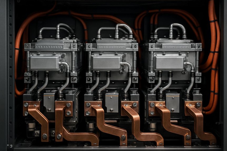
You can view the EMD F125 traction inverter topology as a three-phase voltage source inverter architecture feeding AC traction motors. You’ll see how switching devices and PWM control shape torque, efficiency, and thermal load. You’ll also compare this approach with legacy DC drive and GTO-based locomotive inverters.
Voltage source inverter architecture
Although implementation details can vary by equipment package, the EMD F125 traction inverter topology is best understood as a three-phase voltage source inverter. You start with a high-voltage DC link from the alternator rectification stage, then feed each AC traction motor through a standard three-leg bridge. Each leg uses two controlled switches, creating the phase outputs needed for precise motor torque.
You’ll also find DC link capacitors stabilizing voltage during load changes, low-inductance busbars carrying high current, and gate-drive electronics coordinating safe device operation. This architecture matters because clean power flow reduces electrical stress. It also supports locomotive thermal management and cooling systems by limiting unnecessary heat generation. For rail teams, that means more predictable performance, easier diagnostics, and stronger component life in passenger service.
Switching devices and modulation strategy
Most EMD F125 traction inverter topology discussions point to high-power IGBT switching devices for rail-duty conversion. You typically see modules rated in the kilovolt range, with high current capacity for sustained passenger service. These devices switch the DC link into controlled three-phase output for AC traction motors.
| Element | Typical role | Why it matters |
|---|---|---|
| IGBT module | Switches DC link | Handles rail loads |
| Gate drive | Controls turn-on | Limits stress |
| PWM pattern | Shapes voltage | Smooths current |
| SVPWM option | Uses DC bus well | Improves torque |
| Protection logic | Detects faults | Reduces damage |
You’ll usually evaluate sinusoidal PWM or space-vector modulation. Both strategies shape motor currents, reduce torque ripple, and support precise adhesion control. That improves traction inverter efficiency in locomotives without adding unnecessary mechanical complexity.
Comparison with legacy locomotive inverters
When compared with older DC chopper drives and GTO-thyristor inverter systems, the F125’s VSI architecture gives rail operators finer motor control and simpler maintenance. You get smoother torque regulation because the EMD F125 traction inverter topology shapes three-phase output with modern PWM control. That matters in passenger service, where acceleration, adhesion, and 125 mph stability affect schedules.
Legacy chopper systems controlled DC motors with higher brush wear and heavier rotating maintenance demands. GTO-based inverters improved AC traction, but they used bulkier devices and slower switching. You now benefit from lighter power electronics, cleaner diagnostics, and more modular replacement paths. For procurement teams, that means fewer specialized overhaul tasks. It also supports better locomotive thermal management and cooling systems, since reduced losses ease cabinet heat load.
How Topology Influences Locomotive Efficiency
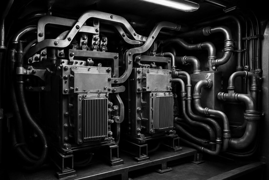
You see the EMD F125 traction inverter topology influence efficiency through lower conversion losses and reduced fuel demand. At 125 mph, it helps manage alternator loading while keeping AC traction motors efficient during part-load operation. You also gain better energy utilization when regenerative braking feeds usable power into HEP loads or braking resistors.
Conversion efficiency and fuel consumption
In high-duty passenger service, conversion efficiency depends on how the inverter manages conduction and switching losses. With the EMD F125 traction inverter topology, you convert DC link power into three-phase motor output while limiting wasted heat. Conduction losses occur as current flows through power devices. Switching losses appear each time devices turn on or off.
- You reduce alternator demand when the inverter wastes less energy as heat.
- Lower fuel burn because the prime mover supplies more usable traction power.
- You improve lifecycle economics through lower energy cost and reduced cooling burden.
For rail engineers, small efficiency gains matter across daily schedules and annual mileage. Higher traction inverter efficiency in locomotives supports better fuel planning, especially under repeated acceleration and station-stop duty cycles without compromising AC traction performance.
High‑speed operation and part‑load behavior
Efficiency gains become more valuable at 125 mph, where sustained cruise power stresses the alternator, DC link, and inverter cooling system. With EMD F125 traction inverter topology, you convert DC link power into stable three-phase motor voltage with fewer wasted losses. That helps you hold schedule speed while limiting heat rise and alternator loading.
At part load, optimized PWM modulation matters just as much. You don’t always run at full output between station stops. You accelerate hard, cruise briefly, then trim power as signals, grades, and dwell patterns change. A voltage source inverter can adjust frequency, voltage, and switching patterns quickly. That improves traction inverter efficiency in locomotives during commuter service profiles. You get smoother torque control, lower thermal cycling, and better use of available engine power.
Regenerative braking and energy utilization
During braking, the AC drive system can reverse power flow and turn traction motors into generators. In the EMD F125 traction inverter topology, the voltage source inverter routes generated energy through the DC link. You can use that energy for head-end power loads when conditions allow, or dissipate it safely through braking resistors.
- You reduce friction brake demand, which cuts wheel, disc, and pad wear.
- Improve energy utilization by capturing useful braking power inside the train.
- You control thermal stress because the inverter manages current, voltage, and resistor loading.
For rail operators, this means less mechanical maintenance and better energy budgeting. It doesn’t make braking losses disappear, but it gives you controlled, predictable energy handling during repeated station stops and downhill operation.
Thermal Management of the F125 Traction Inverter
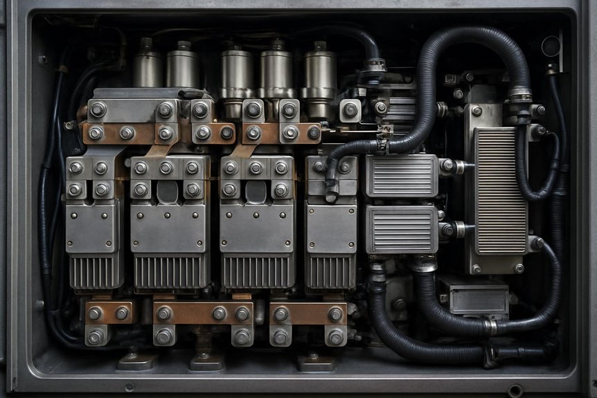
You manage heat from IGBT power modules, busbars, and gate drives before junction limits reduce inverter life. You’ll see how liquid cooling, sensor placement, and airflow protect the F125 inverter cabinet. Good thermal design keeps AC traction systems available and simplifies maintenance during demanding passenger service.
Heat sources and thermal limits in power modules
As the F125 traction inverter converts DC link power into three-phase AC, its main heat sources sit inside the power modules. In the EMD F125 traction inverter topology, you manage junction heating before it becomes a service risk.
- IGBT junctions: You see conduction and switching losses rise with current, PWM frequency, and temperature. That heat narrows safe operating area.
- Freewheel diodes: You control reverse-recovery and conduction losses during motor current commutation. These losses matter during acceleration and braking.
- DC link capacitors: You track ripple current heating, because elevated core temperature shortens capacitor life.
Thermal cycling adds another limit. Each load change expands and contracts bonds, substrates, and solder layers. You protect reliability by keeping junction swings within design margins.
Cooling system design and implementation
Because inverter heat can quickly become a reliability issue, the F125 uses liquid cooling to move losses away from power modules. You typically see coolant routed through cold plates bonded to IGBT stacks, gate-drive areas, and DC link hardware. This supports the EMD F125 traction inverter topology by keeping semiconductor junctions within defined limits during acceleration, braking, and sustained passenger speeds.
You also need heat exchangers sized for locomotive duty, not light industrial service. Pumps circulate coolant through the inverter cabinet, while fans reject heat to ambient air. Temperature, flow, and pressure sensors give the controls early warning before limits become trips. If coolant flow drops or temperature rises, protection logic can reduce output or isolate the affected section. That protects traction inverter efficiency in locomotives without guessing.
Thermal design impact on availability and maintenance
When the inverter holds stable temperatures, power modules experience less thermal cycling and last longer. In the EMD F125 traction inverter topology, that stability protects IGBT junctions, gate drivers, busbars, and capacitors during fast passenger duty.
You gain availability because fewer temperature swings mean fewer cracked solder joints, loosened bonds, or nuisance thermal trips. Inspection intervals can stretch when coolant condition, flow, and sensor data stay within limits.
- You reduce unplanned outages by detecting cooling faults before derating.
- Simplify servicing when filters, pumps, hoses, and heat exchangers remain accessible.
- You control lifecycle cost by replacing modular cooling items without disturbing power stacks.
For maintenance teams, clear access matters. It shortens troubleshooting, improves repair consistency, and keeps locomotives ready for scheduled service.
Reliability and Procurement Considerations
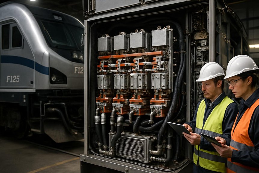
You need modular inverter hardware, redundancy, and fast fault handling to protect availability and also can’t overlook vibration, heat, moisture, and rail-duty cycling when judging environmental robustness. You should weigh lifecycle cost, support quality, and vendor capability before procurement decisions.
Modularity, redundancy, and fault handling
For rail operators evaluating the EMD F125 traction inverter topology, modularity matters as much as efficiency. You need inverter hardware that keeps passenger schedules moving and simplifies depot work. Modular power stacks let your technicians isolate a failed section, remove it, and install a replacement quickly under controlled depot conditions.
- Faster recovery: You reduce troubleshooting time because each stack has defined interfaces, sensors, and service points.
- Managed fault response: The inverter protects itself through overcurrent detection, overtemperature monitoring, and short-circuit shutdown logic.
- Practical redundancy: You limit service disruption by containing faults before they damage adjacent components or traction motors.
You don’t eliminate every failure mode, but you improve maintainability. That supports better availability planning, fewer extended outages, and clearer procurement risk assessment for AC passenger locomotive fleets.
Environmental robustness for rail duty cycles
Because passenger locomotives face constant vibration, shock, humidity, brake dust, and conductive contamination, inverter resilience must be proven before procurement. You should verify that the EMD F125 traction inverter topology uses sealed enclosures, conformal-coated boards, rugged busbars, and secure connectors for rail duty.
Testing matters because small weaknesses become service failures. You’ll want evidence of vibration and shock qualification, thermal cycling, humidity exposure, insulation checks, and contamination resistance. These tests confirm that gate drives, sensors, capacitors, and IGBT power modules remain stable over years of starts, stops, and high-speed operation.
You also need maintainable protection. Filters, pressure monitoring, fault logs, and accessible modules help your team diagnose issues before trips escalate. That’s how reliability of AC traction systems in passenger locomotives becomes measurable.
Evaluating lifecycle cost and vendor options
Environmental robustness only proves part of the business case; lifecycle cost proves the rest. When you evaluate EMD F125 traction inverter topology, connect technical choices to fleet economics. A three-phase voltage source inverter can lower energy losses, cooling stress, and unscheduled removals, but you need evidence before procurement decisions.
Request these vendor data points:
- MTBF by module, gate drive, coolant pump, and control electronics.
- Efficiency curves across passenger duty cycles, not only peak ratings.
- Spares policy, repair turnaround, firmware support, and obsolescence planning.
You’re buying availability, not just hardware. Topology affects total cost of ownership through fuel use, thermal margin, service labor, and inventory strategy. Mikura International helps you review parts support risks honestly, so long-term fleet planning stays practical.
Frequently Asked Questions
Can F125 Inverter Modules Be Repaired During Scheduled Locomotive Maintenance Windows?
Yes, you can often repair or exchange F125 inverter modules during scheduled maintenance windows, unless damage is extensive. Think of one failed module trying to stop a whole passenger fleet like a pebble halting a mountain. You’ll usually isolate faults, review diagnostics, remove modular power stacks, replace cooling seals, and test gate drives. For EMD F125 traction inverter topology support, Mikura International helps you plan serviceable spares and reduce downtime.
What Documentation Should Procurement Teams Request for Traction Inverter Qualification?
You should request qualification test reports, thermal validation data, insulation and dielectric results, vibration and shock compliance, EMC records, failure mode analysis, and lifecycle reliability data. Ask for DC link, IGBT gate drive, cooling loop, and protection settings documentation. Don’t skip service manuals, parts traceability, firmware revision history, and repair criteria. You’ll reduce procurement risk by confirming the inverter matches duty cycle, safety requirements, and maintenance capabilities.
How Does Inverter Software Affect Wheel Slip Control During Passenger Service?
Inverter software keeps wheels biting the rail like boots on wet stone. You get faster torque adjustments from axle speed, motor current, and rail condition signals. The control system trims slip before it grows, so you maintain acceleration, braking stability, and schedule confidence. It also protects AC traction motors, IGBTs, and gearsets from shock loads. During passenger service, that means smoother starts, fewer flat spots, and less unscheduled maintenance.
Are F125 Traction Inverter Components Compatible Across Different Fleet Configurations?
Yes, you can often share some F125 traction inverter components across fleet configurations, but you shouldn’t assume full interchangeability. You need to verify part numbers, software revisions, cooling interfaces, gate-drive settings, and OEM configuration records. Auxiliary loads, HEP demands, and traction motor variants can change requirements. Mikura International helps you confirm compatibility before procurement, reducing inventory risk, avoiding installation delays, and protecting AC traction reliability. Always validate against service documentation first.
What Spare Parts Strategy Supports Long-Term F125 Inverter Availability?
You should stock the small percentage of parts that cause most inverter downtime. Think IGBT power modules, gate drivers, DC-link capacitors, coolant seals, sensors, contactors, and control boards. You’ll reduce risk by pairing onboard spares with depot exchange units and tested vendor-managed inventory. Don’t guess; use failure history, lead times, and fleet duty cycles. Mikura International helps you verify parts, manage obsolescence, and support long-term F125 inverter availability.