


Types of Damper Assemblies Used in Locomotives

Because locomotive suspension systems face constant dynamic loads, damper assemblies come in several distinct configurations. Hydraulic dampers dominate primary suspension applications, offering precise control over vertical oscillations. You’ll find secondary dampers handling lateral and yaw movements between bogie and carbody. Wheelset damper mounting varies materially across these types, affecting overall system responsiveness.
Hydraulic dampers govern vertical precision in primary suspension, while secondary units manage lateral and yaw forces between bogie and carbody.
Friction dampers, though less common today, still appear in older rolling stock. They provide simpler maintenance interval planning but lack the fine-tuning hydraulic units offer. Elastomeric dampers combine damping with vibration isolation, particularly useful where sealing and contamination control matter most.
Your selection process should factor in material fatigue assessment for each type. Steel components in friction dampers wear differently than hydraulic seals under thermal stress. Compatibility with suspension design remains critical when choosing between these options.
Anti-yaw dampers, meanwhile, specifically counter bogie hunting at higher speeds. Each configuration serves distinct operational demands within your locomotive’s overall dynamic behavior.
Why Classification of Damper Assemblies Matters
Since locomotive designs vary widely, damper classification directly impacts procurement accuracy. You need clear categories to match components with specific mechanical demands. Rail engineers rely on this structure for fatigue management across diverse operating conditions. Procurement specialists depend on accurate classification for lifecycle planning and cost control. Correct grouping also supports ride comfort tuning across different locomotive classes.
Classification systems help you address three critical operational factors:
- Compatibility standards ensure dampers integrate correctly with existing suspension systems.
- Maintenance accessibility improves when you select dampers suited to your locomotive’s layout.
- Fatigue management becomes easier with proper damper categorization for stress distribution.
Without structured classification, you risk selecting mismatched components for critical applications. Engineers avoid costly errors when they understand damper distinctions clearly. Precise categorization ultimately reduces downtime while improving overall locomotive performance and reliability.
Primary vs Secondary Suspension Dampers
Primary and secondary suspension dampers serve distinct roles within a locomotive’s suspension architecture. You’ll find primary dampers positioned between the axle and bogie frame, managing wheel-rail interaction forces. Secondary dampers, however, sit between the bogie and carbody, controlling vertical and lateral movements for passenger and crew comfort.
Role of Primary Suspension Dampers
When you carefully inspect a bogie’s suspension layout, you’ll notice two distinct damping stages working together. Primary suspension dampers sit between the axle box and bogie frame, directly influencing wheelset stability under load. They also actively manage hunting suppression, keeping wheel-rail interaction predictable across varying track speeds and curvature. Engineers consistently depend on this damping stage for dynamic load control during frequent track irregularities and gradient changes.
- Axle box motion gets properly regulated, minimizing excessive vertical displacement during operation.
- Bogie frame vibration reduces substantially, delivering smoother wheel-rail contact quality.
- Wheelset alignment stays consistent, ultimately preventing premature component wear over time.
Reliable primary dampers extend service life across the entire bogie assembly substantially. Rail specialists should always prioritize this critical suspension layer during procurement decisions.
Role of Secondary Suspension Dampers
Moving up from the bogie frame, secondary suspension dampers take over ride quality control. You’ll find these units positioned between the bogie frame and the car body. They handle secondary damping, targeting vibrations that primary dampers can’t fully absorb. Your locomotive’s ride comfort depends heavily on this stage of suspension. Engineers design these dampers for car body control during high-speed travel. Sway reduction becomes their primary function, especially when negotiating curves or crosswinds. You’ll notice smoother changes when these dampers work efficiently. Wheelset stability improves indirectly, since reduced body sway lowers stress on lower components. Procurement teams should prioritize dampers with consistent damping coefficients. This ensures long-term reliability across varying operational conditions. Choosing quality secondary dampers safeguards both passenger comfort and structural longevity.
Damper Assembly Types Based on Mechanism
Damper assemblies rely on distinct mechanisms to control locomotive vibrations and oscillations. You’ll encounter hydraulic, friction, and coil spring integrated designs across different applications. Each mechanism type offers unique performance characteristics suited to specific operational demands.
Hydraulic Damper Assemblies
Since hydraulic fluid guarantees energy more consistently than solid materials, engineers favor hydraulic dampers for locomotive suspension systems. You’ll find these assemblies rely on valve based design to control fluid flow precisely. Valves regulate resistance as pistons move through hydraulic fluid, converting kinetic energy into heat.
Hydraulic fluid properties directly influence damping consistency across varying temperatures and loads. Viscosity changes affect how quickly you can expect force generation during operation. Thermal stability becomes critical since locomotives generate substantial heat during extended runs.
Consider these factors when evaluating hydraulic damper assemblies:
- Wear and maintenance requirements determine long-term operational costs.
- Performance testing validates damping consistency under real-world conditions.
- Seal integrity prevents fluid leakage that compromises damping efficiency.
Selecting quality components ensures reliable performance across demanding rail applications.
Friction Damper Assemblies
Friction damper assemblies take a fundamentally different approach than their hydraulic counterparts. You’ll find them using solid contact surfaces to dissipate kinetic energy through friction material selection. Rail engineers often choose these systems for their mechanical simplicity and lower initial cost. However, wear and maintenance demands stay higher than hydraulic alternatives, since friction surfaces degrade over time. Temperature sensitivity remains a key concern, as heat buildup alters friction coefficients during extended operation. You’ll also encounter stick slip behavior, which can create inconsistent damping force and unwanted jerking motions. Noise and vibration control tends to be less refined compared to hydraulic systems. Despite these limitations, procurement specialists still value friction dampers for applications requiring robust, low-maintenance solutions in harsh operating environments.
Coil Spring Integrated Dampers
Several locomotive suspension systems integrate coil springs directly with damping units for dual support. You’ll find this coil spring coupling absorbs vertical shocks while controlling oscillation. Engineers rely on tuned damping to match specific axle load requirements. This setup guarantees balanced load distribution across the bogie frame.
Key functional benefits include:
- Energy dissipation happens through hydraulic resistance paired with spring compression.
- Load distribution improves as coil springs share weight across multiple axles.
- Ride stability increases when damping rates match track irregularities.
You’re getting smoother handoffs between rail joints and curves with this design. Rail engineers often specify this assembly for high-speed locomotive applications.
Classification Based on Direction of Damping
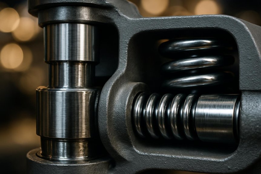
Damper assemblies also get classified by the direction of force they control. You’ll find dampers engineered specifically for longitudinal, lateral, or vertical motion. Each orientation targets distinct dynamic forces that affect locomotive stability and ride quality.
Longitudinal Damping (Yaw Control)
While bogies rotate and swivel through curves, longitudinal dampers control this motion to ensure the direction of travel. You’ll find these components critical for yaw stability assessment across varying speeds. Engineers rely on force feedback sensors to measure resistance during operation. Precise control algorithm tuning ensures dampers respond correctly to different conditions.
Consider these functional priorities when evaluating yaw dampers:
- Track curve behavior directly influences damper sizing and placement decisions.
- Crosswind response mapping helps you predict lateral force impacts on stability.
- Sensor calibration determines how quickly dampers react to directional changes.
Your locomotive’s yaw control system works alongside other damping mechanisms for complete stability. For deeper technical insights, check our dedicated yaw damper article.
Lateral Damping
Because bogies shift sideways during high-speed travel, lateral dampers control this movement effectively. You’ll find these dampers positioned between the bogie frame and the locomotive body. Wheelset hunting causes instability at higher speeds, and lateral dampers counteract this tendency. Bogie frame oscillations reduce materially once you install properly rated dampers.
Your locomotive gains lateral steering stability through consistent damping force distribution. Crosswind vibration mitigation becomes critically essential when locomotives operate across open plains. Axlebox sideplay control works alongside lateral dampers to limit excessive movement.
| Function | Benefit |
|---|---|
| Hunting suppression | Improves speed stability |
| Oscillation control | Reduces frame stress |
| Crosswind resistance | Ensures passenger comfort |
| Sideplay limitation | Extends axlebox lifespan |
Selecting the right damper ensures smoother, safer rail operations.
Vertical Damping
Beyond lateral movement, vertical forces also demand targeted control. You’ll encounter vertical damping methods engineered to manage oscillations from track irregularities. These systems stabilize sprung mass control across bogies, ensuring consistent suspension stability. Engineers rely on this control to maintain axle load balancing during acceleration and braking.
- Hydraulic Vertical Dampers – They absorb shock from rail joints, improving ride comfort tuning.
- Air Spring Assemblies – These regulate load distribution, supporting suspension stability under varying weights.
- Coil-Spring Damper Units – Compact designs enhance sprung mass control on lighter locomotive classes.
Selecting the right assembly depends on axle configuration and operational speed. Procurement specialists must weigh durability against maintenance intervals for long-term reliability.
Application-Based Classification
Damper assemblies vary considerably based on the locomotive type you’re servicing. Diesel-electric locomotives demand dampers that handle engine vibration alongside traction motor dynamics. Electric locomotives, however, require configurations tailored to pantograph stability and different suspension loads.
Diesel-Electric Locomotives
Diesel-electric locomotives depend on multi-stage damping systems to manage engine, traction, and suspension vibrations. Engineers configure dampers to handle tractive load attenuation during high-torque traction events. Traction motors generate forces that require wheel slip steadiness across varying rail conditions. Bogie-mounted dampers support ride quality adjustment for smoother passenger and freight operations.
Three configurations dominate diesel-electric platforms:
- Primary suspension dampers control axle-box movement and absorb track irregularities directly.
- Secondary suspension dampers refine bogie-to-frame interaction, improving overall stability.
- Engine-mount dampers isolate diesel engine vibrations from the locomotive frame.
Thermal effects management becomes critical since engine bays generate substantial heat. Maintenance accessibility design ensures technicians can service dampers without dismantling major components.
Electric Locomotives
Electric locomotives present distinct damper requirements shaped by bogie architecture. You’ll notice bogie geometry effects dictate lateral damper placement across different platforms. Axle load variability demands adjustable damping rates for consistent performance. Suspension travel limits restrict damper stroke length in compact bogie frames. Wheelbase constraints influence longitudinal damper sizing between axles noticeably. Traction control impacts require faster-responding dampers to manage wheel-slip corrections instantly. The table below compares damper specifications across bogie types.
| Bogie Type | Damper Configuration | Key Consideration |
|---|---|---|
| Bo-Bo | Vertical and lateral dampers | Axle load variability |
| Co-Co | Extended-stroke dampers | Wheelbase constraints |
| Articulated | Compact multi-axle dampers | Suspension travel limits |
These variations directly affect how you specify dampers for each locomotive class. Engineers must match damping rates to specific bogie configurations very precisely. Procurement teams should verify compatibility between damper specs and axle load ratings before finalizing orders. Correct selection ensures best ride quality, mechanical reliability, and long-term performance across varying conditions.
How to Choose the Right Damper Assembly Type
How do you select the correct damper assembly for a specific locomotive application? Your choice depends on load characteristics, operating speed, and track conditions. Engineers must evaluate these factors systematically before finalizing any specification.
- Assess load and speed requirements. Heavier locomotives need robust damping ratio tuning for stability. Speed variations demand different ride height selection strategies across service profiles.
- Evaluate track and environmental conditions. Rough tracks require dampers handling higher frequency oscillations. Temperature effects impact fluid viscosity, so climate considerations matter considerably.
- Consider mechanical constraints. Wheelbase constraints limit available mounting space for certain assemblies. Maintenance access planning ensures technicians can service components without excessive downtime.
Combining these three factors helps you narrow down viable options. Reviewing manufacturer specifications against your operational data prevents costly mismatches later. Systematic comparison across these parameters leads to reliable damper selection for any locomotive fleet.
Conclusion: Matching Damper Type to Locomotive Needs
Since every locomotive fleet faces unique operational demands, no single damper type fits all applications. You’ll need to weigh failure modes against your specific route conditions and load profiles. Hydraulic dampers suit high-speed passenger units, while friction types work well for heavy freight service. Consider maintenance intervals when selecting between sealed and serviceable designs. Facilities with limited downtime windows benefit from units requiring less frequent inspection.
Testing standards vary across manufacturers, so you should verify compliance with relevant rail industry certifications. Interface compatibility matters too; mismatched mounting points cause premature wear and alignment issues. Procurement teams must confirm dimensional specs before finalizing orders.
Lifecycle cost ultimately determines value beyond initial purchase price. Factor in replacement parts, labor hours, and expected service life together. Engineers should document performance data across multiple duty cycles for informed comparisons. Your fleet’s long-term reliability depends on matching damper characteristics to actual operating conditions, not generic assumptions.
Frequently Asked Questions
How Often Should Locomotive Damper Assemblies Be Inspected for Wear?
You should inspect damper assemblies every 30,000-45,000 miles of operational mileage, depending on locomotive duty cycles. Follow OEM-recommended inspection intervals rather than generic maintenance schedules. Wear monitoring requires checking seal integrity, fluid levels, and mounting bracket tightness. Service inspections should also assess damping force consistency across varying load conditions. Don’t skip scheduled checks—wear patterns often develop gradually, and early detection prevents costly component failures during high-mileage service.
What Are Common Signs of Damper Assembly Failure?
You’ll notice excessive noise from the damper, signaling internal wear. Check for visible leakage, as fluid loss reduces damping efficiency. Uneven motion often points to bushing degradation within the assembly. Brake pullback creates instability during deceleration cycles. Vibration increase near the mount indicates loosening or fatigue. Watch these five indicators together—they rarely occur alone, and combined symptoms confirm assembly failure requiring immediate replacement.
Can Damper Assemblies Be Repaired or Must They Be Replaced?
A stitch in time ensures nine, and that’s true for damper assemblies too. You’ll find many dampers feature a repairable design, letting you restore function without full replacement. However, severe wear often requires component replacement to maintain safety regulations. Cost viability should inform your decision, weighing repair against replacement expenses. Your maintenance procedures must follow manufacturer guidelines to ensure reliability. Skilled technicians can extend service life through careful inspection and timely intervention.
Which International Standards Govern Locomotive Damper Assembly Quality?
You’ll find several standards governing damper assembly quality across regions. EN 15085 conformity ensures welding and structural integrity for rail applications. TSI requirements set interoperability benchmarks across European rail networks. ISO testing validates material performance and durability under operational stress. NF/EN inspections cover French and European conformity checks for damper components. AAR standards apply if you’re sourcing for North American locomotive fleets. You’ll need cross-referenced certifications when procuring internationally.
Does Climate Affect Damper Assembly Performance in Locomotives?
Yes, climate ensures affects your damper assembly’s performance across operating conditions. Temperature impact alters viscous fluid behavior, changing damping coefficients in cold or hot regions. Humidity variation increases corrosion risk on seals, mounts, and metal housings. You’ll notice lubrication sensitivity becomes critical when grease thickens in freezing climates or thins under heat. Thermal fatigue accelerates wear on rubber and elastomeric components. Selecting climate-appropriate materials ensures your dampers maintain consistent performance year-round.