

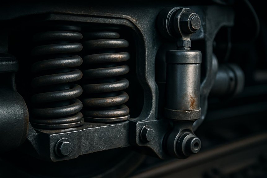
What Is a Damper Assembly? Understanding Its Role in Locomotive Suspension
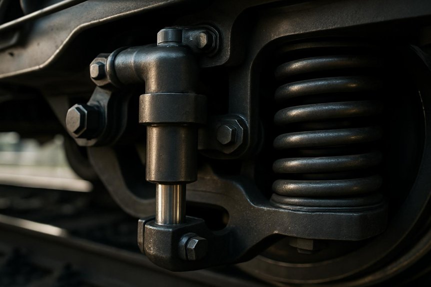
When a locomotive rolls over uneven track, its suspension absorbs constant shocks and vibrations. You’ll find the damper assembly at the heart of this process. It’s a mechanical component that controls oscillations between the bogie and the locomotive body. Engineers rely on it for effective Vibration Management across varying speeds and track conditions.
Your locomotive’s damper works alongside springs to regulate motion. Springs store energy, but dampers dissipate it as heat through hydraulic resistance. This combination stabilises Bogie Dynamics during acceleration, braking, and cornering. Without proper damping, you’d face excessive body sway and reduced ride quality.
Rail engineers specify dampers to prevent resonance at critical speeds. Procurement specialists must select components rated for specific axle loads and operating environments. You’ll notice that damper performance directly affects wheel-rail contact forces. Improper damping accelerates wear on wheels, rails, and other suspension parts, raising maintenance costs considerably.
Introduction to Damper Assembly in Railway Bogies
Because bogies experience continuous dynamic loads, engineers treat the damper assembly as a distinct mechanical unit. You’ll find it mounted between the bogie frame and axle assembly, working independently within the larger suspension system. Engineers design it to control oscillations without relying on other suspension components for basic function.
Suspension kinematics dictates how the damper assembly responds to vertical and lateral movements. Movements transfer through linkages, and the assembly converts kinetic energy into manageable heat dissipation. Kinematics-based design ensures you get consistent damping across varying speeds and track conditions.
Failure mode analysis helps you identify where an assembly’s structural boundaries lie. Boundaries define where the damper’s responsibility ends and the broader suspension system begins. Analysis also reveals why isolating the assembly matters for maintenance and inspection purposes.
Standalone treatment gives procurement specialists a clearer framework for evaluating component quality. Frameworks like this set the stage for a deeper structural breakdown ahead.
Core Function of a Damper Assembly
Structural boundaries only tell part of the story; the damper assembly’s core function reveals its true purpose. You’ll find its main job is absorbing kinetic energy from bogie oscillations. This energy converts into heat through frictional damping mechanisms inside the assembly. Frictional damping controls both amplitude and frequency of unwanted vibrations. As you monitor performance, you’ll notice how temperature effects influence damping efficiency over time. Excessive heat can reduce fluid viscosity, weakening resistance to motion.
You’ll want dampers engineered to withstand these temperature effects without losing consistency. Precision-machined components ensure smooth energy dissipation across varying speeds. Every stroke cycle demands controlled resistance to prevent harsh jolts. Engineers design internal valves to regulate flow rates precisely. This regulation keeps oscillations dampened without compromising ride stability. You’ll appreciate how Mikura International’s expertise in supplying genuine spares ensures reliable damping performance. Their components deliver consistent frictional damping despite fluctuating temperature effects, maintaining stability across diverse operating conditions and demanding rail environments worldwide.
Key Components of a Damper Assembly
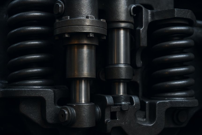
You’ll find that every damper assembly relies on four critical components working in unison. Each part, from the piston and cylinder unit to the valve mechanisms, serves a distinct purpose. Understanding these components helps you evaluate performance, durability, and maintenance needs more effectively.
Piston and Cylinder Unit
Since the piston fits precisely within the cylinder bore, it controls fluid flow during compression and rebound. You’ll notice the piston motion translates locomotive vibrations into controlled hydraulic resistance. This resistance dampens oscillations, protecting the locomotive’s structural integrity during operation.
The cylinder houses precision-machined walls that guide piston movement without leakage. Fluid gets forced through narrow orifices as the piston travels, generating resistance against motion. You can observe this process through several key stages:
- Piston pushes fluid through calibrated valve ports
- Cylinder walls maintain consistent pressure distribution throughout the stroke
- Fluid viscosity increases resistance during rapid piston movement
- Valve orifices regulate flow rate for smooth dampening action
Mikura International supplies precision piston-cylinder units engineered for demanding rail applications.
Sealing System
Beyond the piston-cylinder unit, sealing components keep the entire damper functional under pressure. You’ll find these seals positioned strategically to block fluid leakage at critical points. Piston rod seals prevent hydraulic fluid from escaping during compression and rebound strokes. O-rings maintain tight contact between mating surfaces, stopping external contamination from entering.
Seal material selection directly impacts your damper’s operational lifespan and performance consistency. Engineers typically choose Viton, nitrile, or PTFE based on temperature and chemical exposure requirements. These materials resist wear from continuous friction against moving components.
Pressure retention reliability depends heavily on proper seal installation and maintenance schedules. You’ll need to inspect seals regularly since degraded seals cause pressure loss and reduced damping efficiency. Mikura International supplies precision-engineered sealing components built for demanding locomotive applications.
Mounting Brackets and End Fittings
Mounting brackets and end fittings anchor the damper assembly to the bogie frame and axle. You’ll find these components engineered for precise bushing alignment and consistent bracket load transfer. Rubber-metal bushings absorb high-frequency vibrations while maintaining structural contact. Eyelets provide pivoting connections, allowing the damper to articulate during suspension travel. Brackets distribute forces evenly across the frame, preventing localized stress concentrations.
Your inspection routine should verify these connection points regularly:
- Bushings show no cracking, hardening, or excessive wear
- Eyelet pins rotate freely without binding
- Brackets remain free of fatigue cracks or deformation
- Fasteners maintain specified torque values consistently
Proper alignment at each attachment point ensures efficient force transmission. Misaligned fittings accelerate wear and compromise damping performance across the bogie system.
Valve and Flow-Control Mechanisms
Once brackets and bushings secure the damper, internal valves take over the real work. You’ll find these valves controlling oil movement between chambers under pressure. Flow path routing determines how quickly fluid shifts during compression and rebound strokes. Precise routing prevents turbulence and keeps damping forces consistent across varying speeds. Valve timing control adjusts when ports open or close during piston movement. This timing directly affects how the locomotive absorbs track irregularities. You’ll notice engineers calibrate valve stacks with washers and springs for specific stiffness. Stiffness levels change resistance based on load and speed conditions. Mikura International supplies these calibrated valve components for demanding rail applications. Each part meets strict tolerances required for consistent locomotive performance. Reliable valves ensure smoother rides and reduced mechanical wear over time.
Working Principle of a Damper Assembly
Every damper assembly relies on converting kinetic energy into heat to control locomotive motion. You’ll find this process governed by a damping force curve, which maps force against piston velocity. Understanding this curve helps you predict how the damper responds under varying operating conditions.
Conversion of Kinetic Energy to Heat
Locomotive dampers convert kinetic energy into heat through controlled fluid displacement. You’ll notice fluid gets forced through narrow orifices during compression and rebound strokes. This restriction creates significant pressure drop across the valve assembly. Orifice throttling controls how quickly fluid moves between chambers, directly affecting damping force. Engineers must account for valve cavitation, which occurs when fluid pressure drops below vapor pressure. Poor design leads to bubble formation and premature component wear.
Here’s what happens inside the damper during operation:
- Fluid enters narrow passages, creating resistance against piston movement.
- Molecules collide rapidly, generating friction and heat generation within the chamber.
- Pressure differentials build across valve seats, controlling flow rate precisely.
- Temperature rises as mechanical energy transforms into thermal energy continuously.
You gain smoother rail performance through this precise energy conversion process.
Damping Force Curve and Its Significance
Because piston velocity constantly changes, damping force must adjust in response. You’ll notice this relationship follows a specific curve, not a straight line. Engineers rely on valve characterization to shape this curve precisely. Low-speed movements require gentle resistance for ride comfort. Higher velocities demand stronger damping to control harsh impacts. Fluid dynamics within the damper dictate how oil flows through valve orifices. Restrictive passages create back-pressure, generating the force you need at each speed. Precise tuning prevents excessive stiffness during minor vibrations. Aggressive damping only activates when velocity spikes during rough track conditions. You’ll find this engineered curve balances comfort with structural protection, ensuring locomotives handle diverse operating conditions without compromising ride quality or component longevity.
Where the Damper Assembly Fits in the Bogie Suspension System
Within the bogie frame, the damper assembly sits between the axle box and the bogie frame, working alongside primary springs. You’ll notice its placement directly shapes bogie kinematics during operation. Springs absorb vertical shocks, while dampers regulate motion timing between components. Together, they create a coordinated spring linkage that stabilizes wheel-to-frame interaction. Engineers rely on this arrangement to manage forces transmitted through axle box interfaces.
- Axle box interfaces transfer wheelset movement into the suspension system smoothly.
- Wheelset coupling keeps both wheels synchronized during curves and speed changes.
- Primary springs cushion vertical loads before dampers absorb excess energy.
- Damper mounts attach directly to axle box interfaces for immediate response.
This layout keeps the wheelset aligned under varying rail conditions. Bogie kinematics stay controlled because springs and dampers share load paths efficiently. Precision in this system-level design supports safer, smoother locomotive travel across diverse rail networks.
Visualizing Damper Assembly Parts (Exploded View Concept)
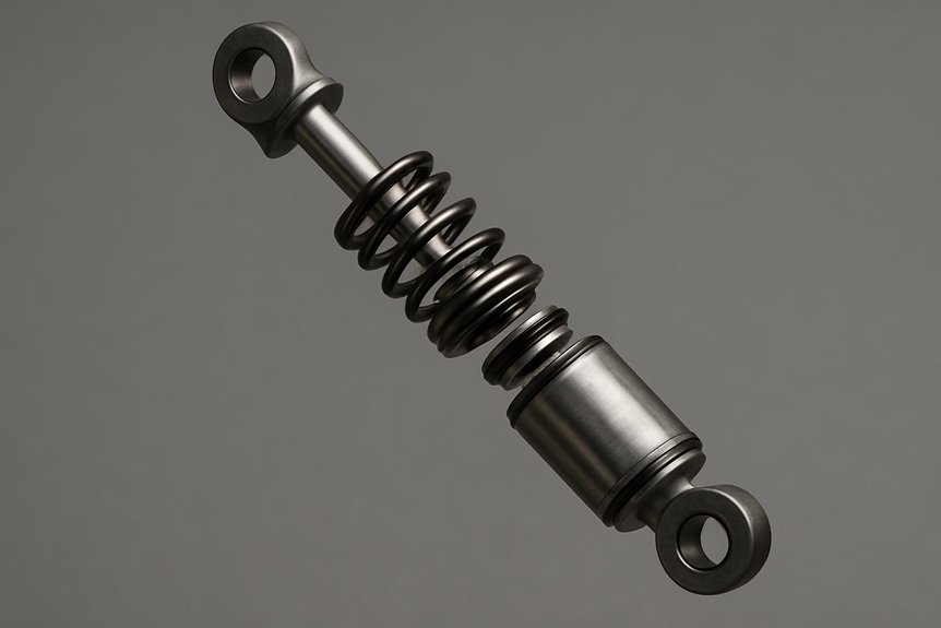
Since spatial relationships aren’t always obvious from assembled views, an exploded diagram clarifies component positioning instantly. A labeled exploded view separates each damper part along its assembly axis. Engineers can trace how the piston rod connects to the mounting bracket. Procurement specialists benefit from seeing exact part placement before ordering replacements. Pairing this with a cross sectional view reveals internal seal arrangements and fluid chambers. Together, these visuals eliminate guesswork during maintenance planning.
| Component | Position in Assembly | Function |
|---|---|---|
| Piston Rod | Center axis | Transfers motion |
| Outer Cylinder | Surrounding housing | Contains hydraulic fluid |
| Mounting Bracket | Top and bottom ends | Secures to bogie frame |
Referencing such diagrams during procurement reduces ordering errors markedly. Technicians rely on this visual clarity for accurate disassembly sequences. Mikura International recommends keeping labeled exploded diagrams on hand for every damper model. Doing so speeds up fault diagnosis across different locomotive fleets.
Conclusion: Why Structural Knowledge of Damper Assembly Matters
Understanding damper assembly structure gives engineers a clear edge in fault diagnosis. You’ll spot irregular wear patterns faster when you know each component’s role. Procurement specialists also benefit, since structural clarity supports smarter sourcing decisions. Knowing part interactions helps you predict failure modes before they escalate. This awareness strengthens maintenance diagnostics and reduces unplanned downtime across your fleet.
Structural knowledge directly shapes several operational outcomes:
- Refurbishment intervals become easier to plan with accurate wear data.
- Safety compliance checks improve when you understand load-bearing components clearly.
- Diagnostic accuracy increases once you recognize early signs of component fatigue.
- Procurement choices get sharper when you match parts to precise specifications.
You’ll make better decisions when you grasp how each part functions. Choosing reliable parts strengthens locomotive performance and long-term operational safety.
Frequently Asked Questions
How Often Should Locomotive Damper Assemblies Be Inspected for Wear?
Think of damper wear like a slow-burning fuse—you won’t notice until it’s too late. You’ll want to inspect dampers every 3-6 months, though inspection intervals vary based on operating conditions. Harsh routes demand tighter checks; milder duty cycles allow flexibility. Your service records guide these decisions effectively. Don’t skip visual inspections for leaks, corrosion, or mounting wear. Mikura International recommends pairing scheduled checks with performance monitoring for maximum damper longevity.
What Causes Premature Failure in Railway Damper Assemblies?
You’ll often trigger premature failure through corrosion fatigue in the damper’s mounting brackets. Moisture and vibration combine, weakening metal joints over time. Seal degradation also plays a major role in reducing damper lifespan. Once seals harden or crack, hydraulic fluid leaks out quickly. You should watch for contaminated fluid, since it accelerates internal wear. Excessive heat exposure further stresses seals, causing premature cracking. Inspecting seals and brackets regularly helps you catch corrosion fatigue before it spreads.
Can Damper Assemblies Be Repaired Instead of Replaced?
Yes, you can repair damper assemblies when field troubleshooting confirms internal wear hasn’t compromised structural integrity. Repair feasibility depends on cylinder condition, rod straightness, and seal degradation levels. You’ll often achieve reliable results through sealing replacement, especially when leakage stems from worn O-rings or gaskets. Component refurbishment works well for valves, pistons, and mounting bushes. However, you shouldn’t attempt repairs on cracked housings—replacement remains safer there.
Which Maintenance Tools Are Required for Damper Servicing?
You’ll need torque wrenches, hydraulic pressure gauges, and seal pullers for damper servicing. Torque settings must be verified using calibrated tools to prevent mounting failures. An inspection checklist helps you track piston wear, fluid levels, and bushing condition systematically. Feeler gauges assist in measuring clearance tolerances accurately. Diagnostic testers evaluate damping force output against OEM specifications.
Does Climate Affect Damper Assembly Performance in Locomotives?
Yes, climate acts like a silent throttle on your damper’s efficiency. You’ll notice thermal expansion effects altering seal tolerances and piston clearances in extreme heat. Cold conditions bring lubrication viscosity changes, thickening fluid and reducing damping response. Your damper assembly faces constant stress from temperature swings across operating regions. Don’t overlook seasonal inspections, since they’ll catch viscosity-related issues early.