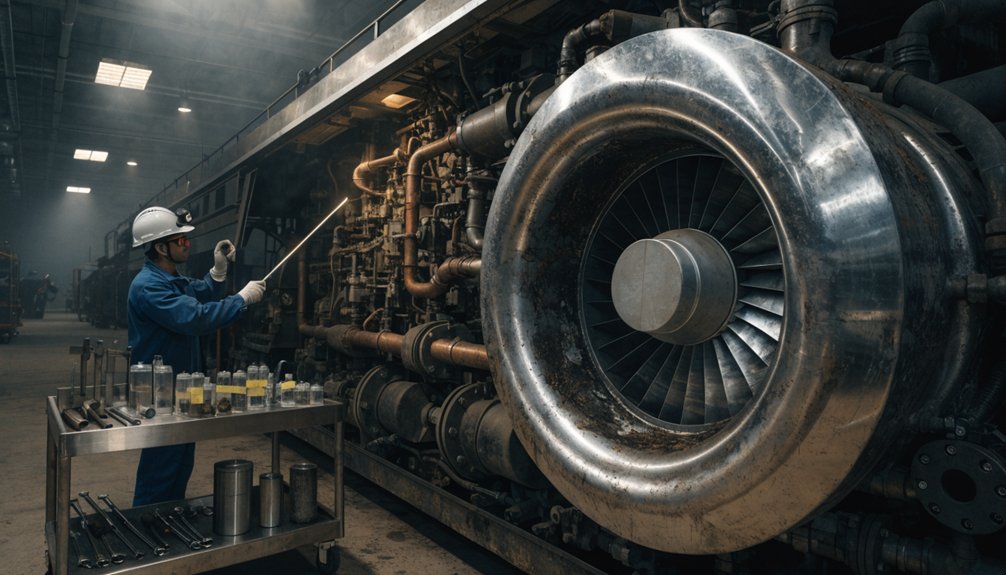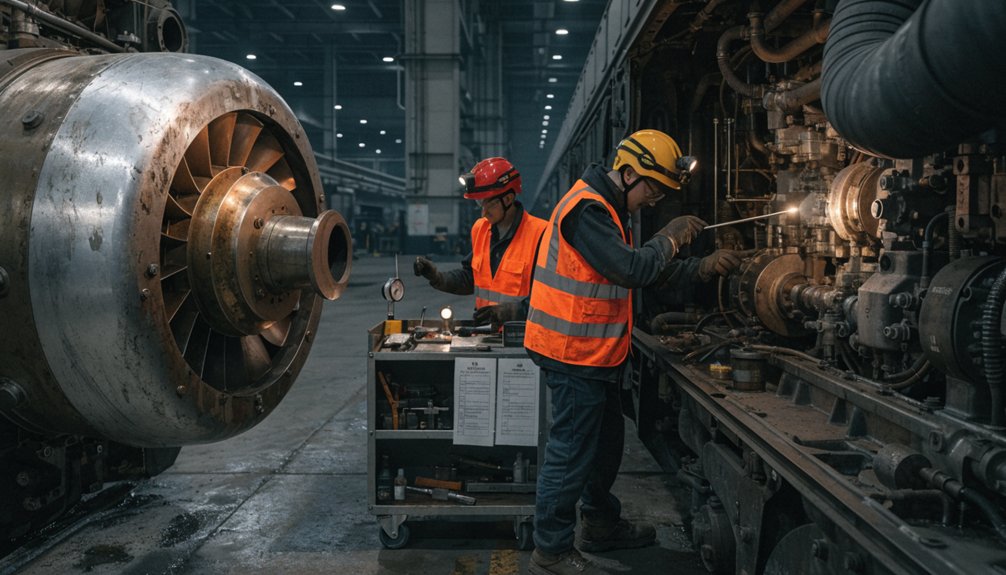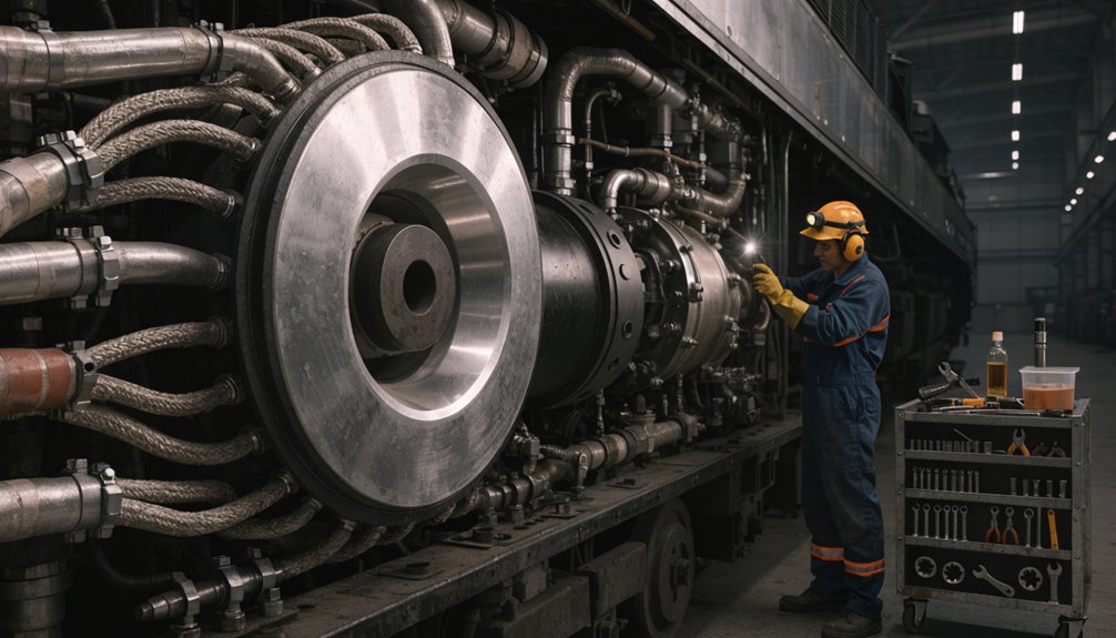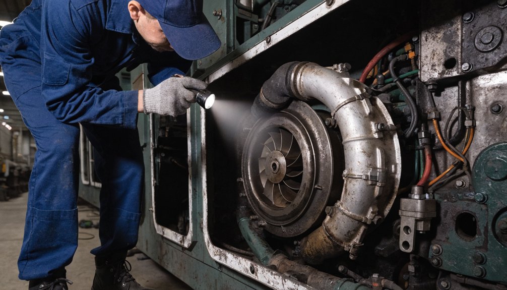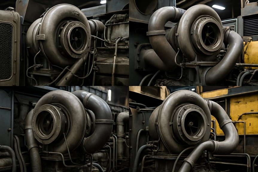
How the EMD 710 turbocharger Actually Makes Life Better

How the EMD 710 turbocharger Actually Makes Life Better

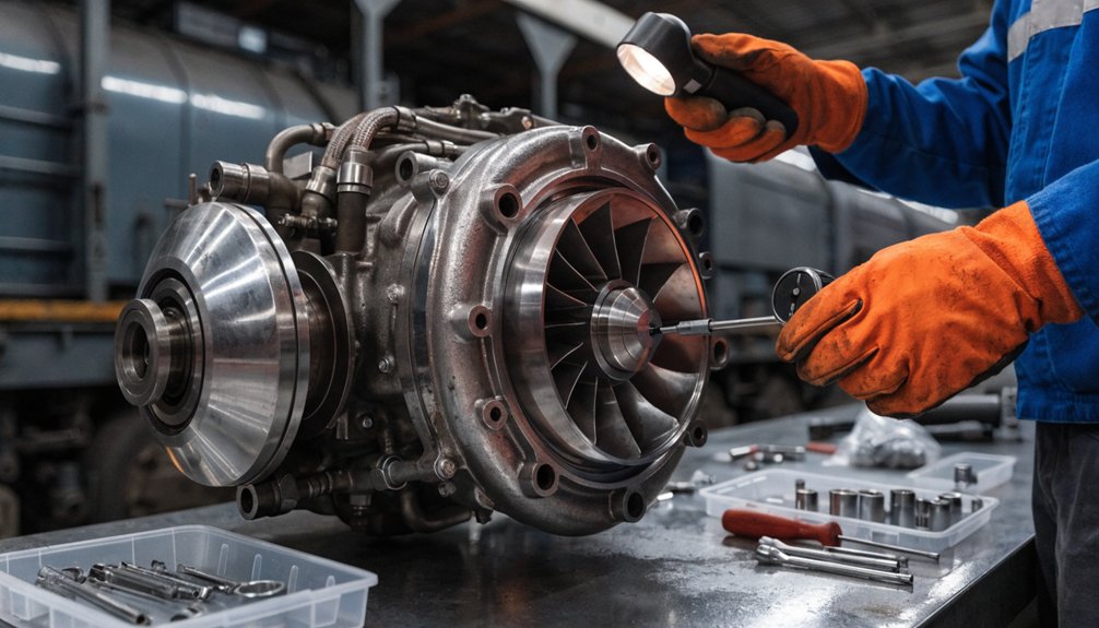
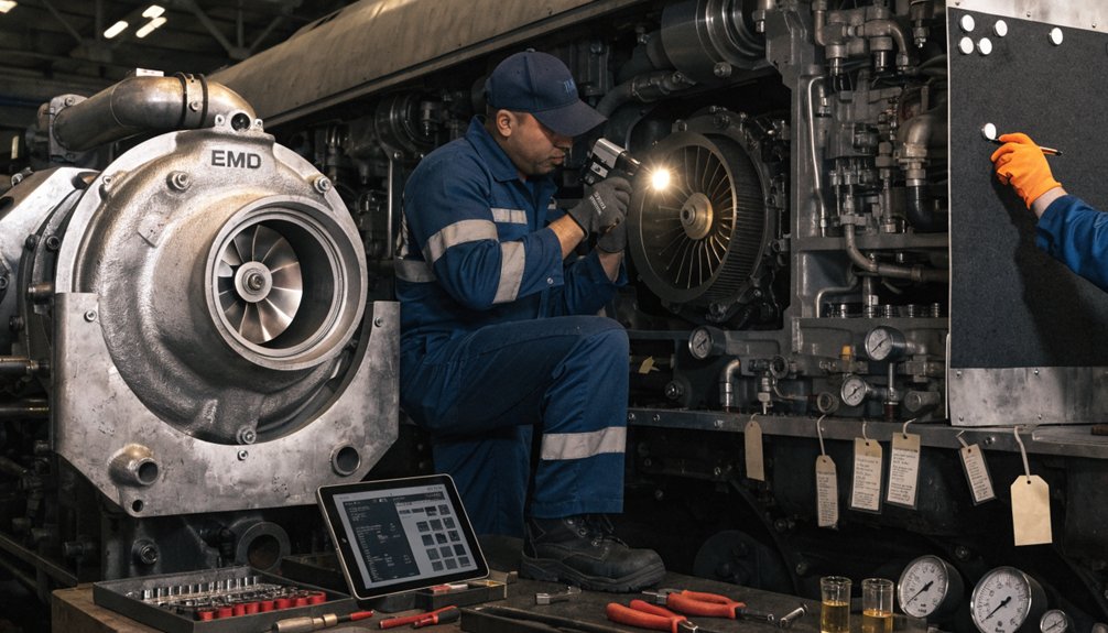
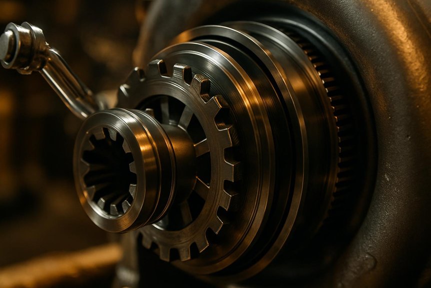
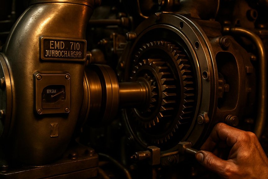
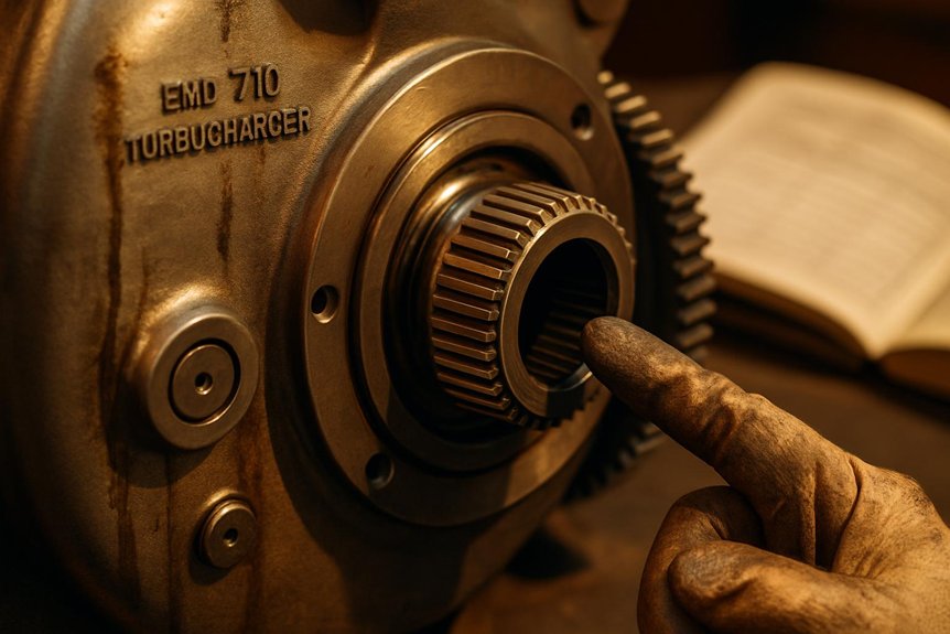
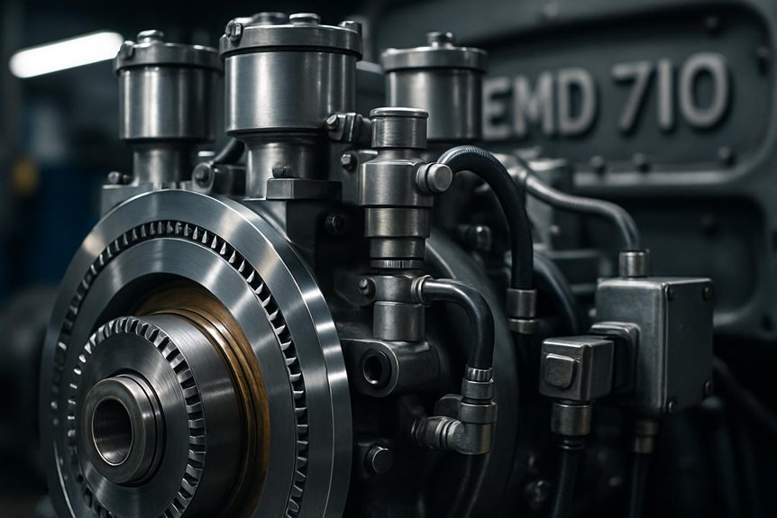
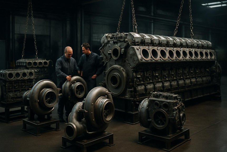
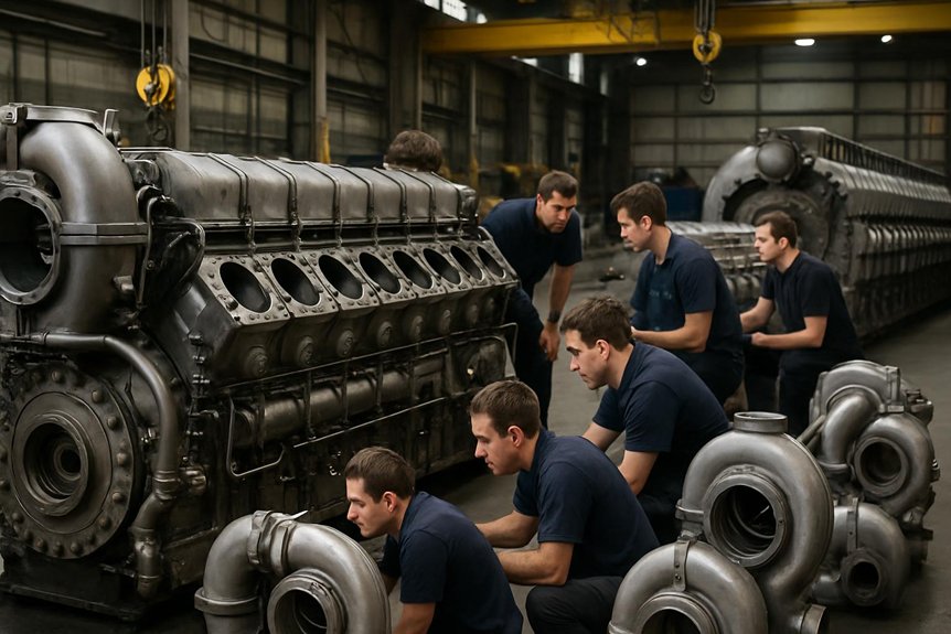
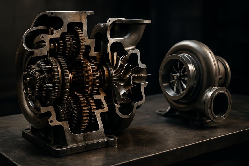
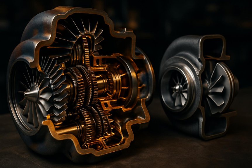
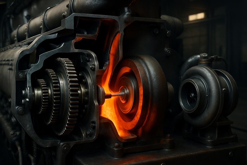
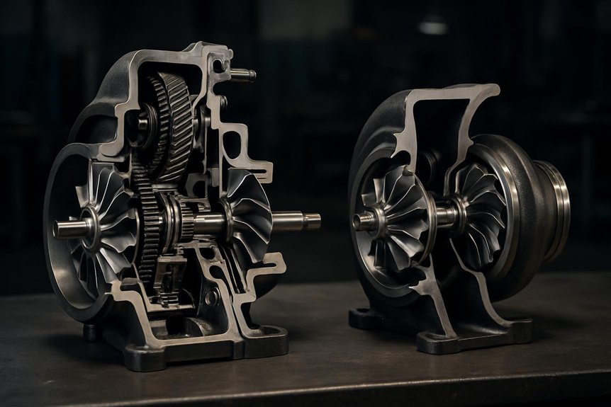
Let’s understand the EMD 710 turbocharger: When you’re operating an EMD 710 locomotive at low loads, the gear train mechanically drives the turbocharger compressor to maintain scavenging pressure. As exhaust energy increases and turbine speed exceeds gear-driven speed, the overrunning clutch disengages automatically—no external control input required. That 3–5% RPM differential threshold governs the handoff, while hysteresis prevents clutch hunting during load cycling. Understanding the full transition mechanics, wear patterns, and maintenance triggers reveals considerably more about keeping this system reliable.

How is clutch engagement/disengagement managed on EMD 710 turbochargers during transition from gear-driven to free-turbine operation in locomotives?

The EMD 710 turbocharger utilizes a specialized overrunning clutch system. This mechanism manages the transition from gear-driven to free-turbine operation. At low loads, the gear train drives the compressor directly. This ensures adequate scavenging air for the two-stroke diesel engine. As load increases, exhaust gas energy rises significantly.

The turbine wheel begins to accelerate rapidly due to this energy. Eventually, the turbine speed exceeds the mechanical gear drive speed. The overrunning clutch then disengages automatically without external control inputs. This freewheeling action prevents mechanical shock and potential damage. It allows the turbocharger to operate efficiently in free-turbine mode.

The system relies on precise differential speed detection for engagement. Lubrication quality critically impacts the clutch engagement reliability. Oil viscosity determines the friction characteristics within the clutch assembly. Proper maintenance ensures smooth transitions during varying locomotive operating conditions. Engineers must monitor these parameters for optimal performance. Procurement specialists should prioritize clutch durability specifications. This design enhances overall locomotive fuel efficiency and reliability.

Key Takeaways

  • The overrunning clutch automatically disengages when exhaust-driven turbine speed exceeds gear-driven speed, requiring no external control input to trigger the transition.
  • Gear train preload forces press clutch rollers against the inner race during low-speed operation, sustaining mechanical torque delivery to the compressor shaft.
  • A 3–5% RPM differential buffer zone separates engagement and disengagement trigger points, preventing clutch hunting between operating modes.
  • Oil viscosity directly affects clutch response timing; cold oil slows transitions while elevated temperatures compromise engagement surface oil film support.
  • Transition hysteresis, typically a 2–5% differential speed band, prevents compressor surge and mechanical resonance during load cycling events.

Architecture and Operating Modes

Architecture and Operating Modes | EMD 710 turbocharger

When you work with the EMD 710 turbocharger, you’re managing a two-stroke engine that demands reliable scavenging air across all load conditions. The gear train delivers torque directly to the compressor shaft, ensuring boost pressure before exhaust energy suffices. Understanding this torque path and baseline component layout is essential before examining how the overrunning clutch changes everything.

Two-Stroke Scavenging Needs and Boost

Two-stroke diesel engines can’t scavenge cylinders effectively without sufficient boost pressure at low speeds. Unlike four-stroke engines, they rely entirely on pressurized air to purge exhaust gases and charge cylinders. Without adequate scavenging aircombustion efficiency collapses rapidly.

At idle and low notch positions, exhaust energy remains too weak to spin the turbocharger freely. The EMD 710 turbocharger addresses this directly through its gear-driven assist mechanism. The gear train mechanically drives the compressor, delivering the boost pressure your engine needs immediately.

This assisted boost maintains the minimum air-to-fuel ratio required for clean combustion. It prevents cylinder scavenging failure, reduces thermal stress on pistons, and protects against incomplete combustion. Your engine operates reliably across all load ranges because the assist system eliminates the low-speed boost deficit entirely.

Gear Train and Torque Path

From the crankshaft gear, mechanical torque travels through a dedicated gear train directly to the turbocharger’s compressor wheel. This path ensures your two-stroke engine receives adequate scavenging air at low loads. Each gear stage multiplies rotational speed before reaching the compressor shaft. Torque flows continuously through this mechanical chain during startup and low-power operation.

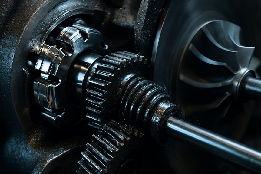
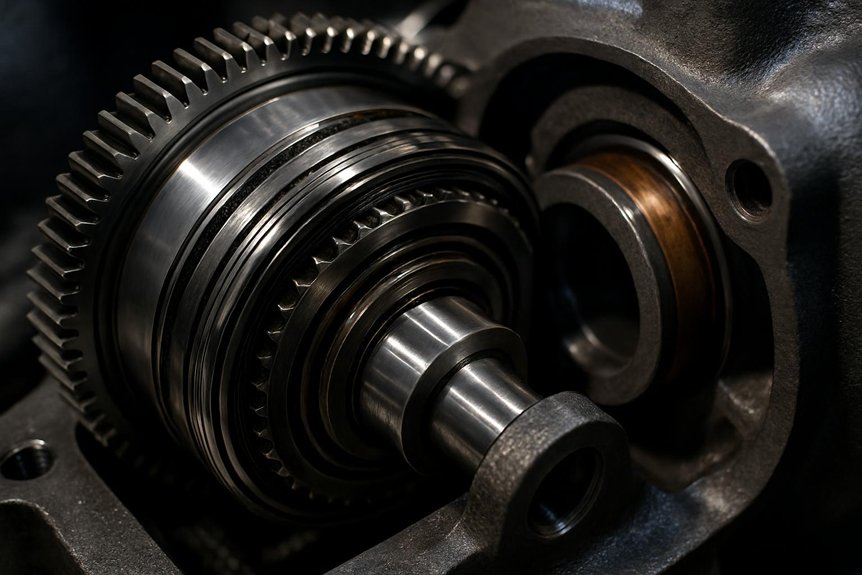
At the heart of this system sits the overrunning clutch. It connects the gear train to the turbocharger shaft mechanically. When exhaust energy accelerates the turbine beyond gear-driven speed, the clutch releases automatically. Your gear train stops driving the compressor at that precise moment.

Understanding this torque path helps you anticipate switching behavior. Maintaining gear train integrity directly protects compressor response during critical load changes.

EMD 710 turbocharger Baseline Components

Understanding the torque path sets the stage for examining what physically makes it possible.

The EMD 710 turbocharger assembly centers on four interdependent components. Each one directly influences transitory behavior during load changes.

Compressor wheel — draws ambient air and delivers pressurized charge air to engine cylinders.

Turbine wheel — extracts exhaust gas energy, converting it into rotational shaft work.

Rotor shaft — connects both wheels mechanically, transmitting torque between them under all operating conditions.

Overrunning clutch assembly — interfaces the gear-driven assist mechanism with the rotor shaft at the critical transitory threshold.

Shaft support relies on precision journal bearings lubricated under continuous pressurized oil flow. These bearings sustain radial and axial loads across both operating modes.

You’re working with a system where component integration—not individual parts—determines reliability.

Clutch Mechanics and Transition Physics

Clutch Mechanics and Transition Physics

When you examine the EMD 710 turbocharger’s overrunning clutch, geometry and load conditions define its entire operating logic. At low locomotive loads, the gear train mechanically drives the compressor, ensuring adequate scavenging air for the two-stroke diesel cycle. Once exhaust energy accelerates the turbine beyond gear-drive speed, the clutch disengages automatically, moving the system into free-turbine mode.

Overrunning Clutch Geometry and Design

The overrunning clutch inside the EMD 710 turbocharger relies on precisely shaped sprag or roller elements. Each element wedges between inner and outer races at a calculated angle. Wedging angles typically range between 5° and 12°, depending on design. These angles determine engagement torque sensitivity and release speed.

Element TypeWedging Angle Range
Sprag5° – 8°
Roller8° – 12°
Sprag (heavy load)6° – 9°
Roller (standard)9° – 11°
High-speed sprag5° – 7°

Tighter angles improve torque transmission during gear-driven assist. Shallower angles enable faster disengagement into free-turbine mode. Your clutch’s geometry directly controls transition smoothness and mechanical load distribution across races.

Engagement Under Low Load Conditions

At low locomotive loadsgear-driven assist keeps the compressor spinning through mechanical torque transfer. The gear train imposes a preload force on the clutch rollers, pressing them firmly against the inner race. This contact stress ensures immediate torque delivery to the compressor shaft. You’re relying on the clutch’s wedging geometry to sustain this mechanical coupling.

Torque flows from the gear drive into the compressor, maintaining adequate scavenging pressure for the two-stroke diesel cycle. Without sufficient exhaust energy, the turbine can’t self-sustain rotation. Mechanical drive compensates directly for this shortfall.

Contact stresses across the roller-race interface remain proportional to transmitted torque. Higher preload forces reduce slip risk but increase wear rates over time. Monitoring these parameters helps you anticipate clutch degradation before it affects locomotive performance.

Disengagement to Free Turbine Operation

As turbine speed climbs beyond the gear drive’s rotational threshold, the overrunning clutch disengages automaticallyDifferential speed drives this shift—no external control input triggers it. Once exhaust energy accelerates the turbine wheel past mechanical drive speed, the clutch ratchets into freewheeling. Sprags or rollers within the clutch assembly rotate away from their locked position. This removes the mechanical load path between the gear train and the turbocharger shaft.

You’re now operating in free-turbine mode. Exhaust gas enthalpy alone sustains compressor output. Gear-train drag no longer burdens the turbine shaft, improving thermodynamic efficiency noticeably.

Shift happens within milliseconds at the crossover threshold. Abrupt load changes can cause brief re-engagement cycles. Monitoring shaft speed differential helps you identify erratic clutch behavior early. Precise disengagement protects both the gear train and turbocharger bearings from shock loading.

Control, Thresholds, and Hysteresis

Control, Thresholds, and Hysteresis

When managing the EMD 710’s assisted turbocharger, you’ll encounter precise speed and pressure thresholds that govern clutch engagement and release. Oil temperature directly influences viscosity, altering friction characteristics and shifting those thresholds unpredictably. You must also account for transition hysteresis—the deliberate lag that prevents surge and mechanical resonance during load cycling.

Speed and Pressure Transition Thresholds

Transition thresholds govern when the overrunning clutch engages or disengages within the EMD 710 turbocharger system. You’re working with two defined bands: gear-driven mode operates below approximately 60–65% of rated turbine RPM. Free-turbine mode activates above that threshold as exhaust energy overtakes mechanical drive speed. Boost pressure mirrors this shift. Below roughly 8–10 psi manifold pressure, the gear train sustains compressor output. Beyond that range, turbine-generated boost becomes self-sustaining. These bands aren’t arbitrary—they’re calibrated to the 710’s two-stroke scavenging requirements. Hysteresis prevents rapid cycling by building a buffer zone between engagement and disengagement points. Typically, a 3–5% RPM differential separates these trigger points. Monitoring both turbine speed and manifold boost simultaneously gives you the clearest picture of transition health.

Oil Temperature and Viscosity Effects

Oil temperature directly controls how the overrunning clutch responds during load changes. Cold oil increases viscosityslowing clutch response during gear-to-turbine transitions. Elevated temperatures reduce viscosity, compromising the oil film that supports clutch engagement surfaces. You’ll see engagement timing drift when oil operates outside its designed thermal window.

Three critical viscosity-related failure conditions affect clutch performance:

  • Cold-soak starts: High-viscosity oil delays roller or sprag element movement, causing sluggish disengagement
  • Thermal runaway zones: Thin oil accelerates surface wear on clutch ramps, reducing service life
  • Viscosity index breakdown: Degraded oil loses consistent behavior across temperature ranges, introducing engagement unpredictability

Monitoring lube oil temperature during notch transitions gives you early warning of viscosity drift. Maintaining oil within specification directly protects clutch reliability across all locomotive operating conditions.

Surge and Resonance Avoidance Strategies

Viscosity drift doesn’t just affect engagement timing—it sets the stage for compressor surge and mechanical resonance.

You must define clear speed-differential thresholds to control engagement hysteresis. Without defined upper and lower trip points, the clutch hunts between gear-driven and free-turbine modes. That cycling generates resonance in the compressor section.

Your control logic should enforce a hysteresis band—typically 2–5% differential speed—before allowing mode changes. This prevents rapid toggling under fluctuating exhaust energy conditions.

Surge avoidance requires coordinating fuel rack position with compressor inlet conditions during changeover. Rapid load increases outpace scavenging air supply, collapsing pressure ratios and triggering surge.

Monitor inlet manifold pressure continuously. Detect pressure oscillations early to distinguish surge onset from normal transient behavior.

Proper threshold calibration protects both clutch longevity and compressor structural integrity across varying locomotive duty cycles.

Reliability, Monitoring, and Maintenance

Reliability, Monitoring, and Maintenance

Sustained clutch performance depends on how well you track wear, interpret diagnostic signals, and schedule overhauls. You’ll find that failure modes often surface gradually through measurable indicators before causing operational disruption. Understanding these patterns lets you establish targeted inspection intervals and make informed rebuild decisions.

Wear Patterns and Failure Modes

Wear inside the overrunning clutch assembly follows predictable failure progressions. Identifying these patterns early prevents costly unplanned locomotive downtime. Three primary failure modes demand your attention:

  • Sprag spalling: Repeated stress cycling fractures sprag contact surfaces, reducing load transfer capacity progressively.
  • Cage wear: Abrasive debris accelerates cage degradation, causing misalignment and erratic engagement behavior.
  • Heat discoloration: Thermal overload from insufficient lubrication leaves characteristic blue-black oxidation marks on sprags.

Each failure mode leaves distinct physical evidence during inspection. Spalling generates metallic debris detectable through oil analysisCage wear manifests as increased rotational play during manual clutch checks. Discoloration confirms oil starvation events have already compromised clutch metallurgy. Addressing these indicators promptly protects your EMD 710 turbocharger’s operational integrity and switching reliability.

Instrumentation and Diagnostic Techniques

How do you catch clutch degradation before it becomes locomotive downtime? Monitoring three key parameters gives you early warning.

Speed deviation between the gear drive and turbine shaft signals clutch slip. Boost pressure drops indicate incomplete free-turbine engagement. Vibration signatures reveal mechanical wear inside the clutch assembly.

Trending these signals together exposes developing faults before catastrophic failure occurs.

ParameterFault Indication
Turbine shaft speedAbnormal differential vs. gear drive
Boost pressureBelow-threshold output at rated load
Vibration amplitudeElevated signatures during phase
Oil pressure/temperatureDegraded lubrication affecting engagement

Correlating all four channels simultaneously accelerates diagnosis meaningfully. You’re not chasing isolated readings—you’re reading system behavior. Mikura International recommends continuous data logging across these channels for fleet-wide reliability programs.

Rebuild and Overhaul Interval Guidelines

Diagnostic data only delivers value when it drives scheduled action. You should align overhaul windows with actual clutch life drivers, not fixed calendar dates. Operational hours, thermal cycling frequency, and oil contamination history all determine true wear progression.

Key interval triggers to track include:

  • Accumulated engagement cycles exceeding manufacturer-rated thresholds for your specific duty profile
  • Oil analysis results showing metallic particulate spikes indicating ramp wear or roller fatigue
  • Transition anomaly logs from prior diagnostic sessions flagging repeated slip events

Waiting for failure introduces unplanned downtime—far more costly than a scheduled overhaul. Mikura International recommends reviewing clutch condition data every major maintenance block. Rebuilding proactively preserves engagement reliability and protects the broader EMD 710 turbocharger assembly from secondary damage.

Procurement and Lifecycle Decisions

Procurement and Lifecycle Decisions

When sourcing components for the EMD 710 turbocharger system, you must prioritize clutch durability ratings over unit price alone. Your spares strategy should account for overrunning clutch wear cycles, retrofit compatibility, and fleet-wide standardization. Total cost of ownership analysis reveals that quality components reduce changeover failures and extend service intervals considerably.

Specification and Spares Strategy

Three critical specification pillars govern clutch procurement for the EMD 710 turbocharger overrunning system.

Clutch ratings, material standards, and interchangeability requirements define your spares strategy’s foundation. Ignoring any pillar creates costly fleet vulnerabilities.

  • Clutch ratings: Verify torque capacity against your locomotive’s maximum gear-drive load conditions.
  • Material standards: Specify hardened steel ratchet pawls and heat-resistant cage alloys meeting OEM metallurgical grades.
  • Interchangeability requirements: Confirm dimensional compatibility across your fleet’s turbocharger variants before bulk procurement.

Mikura International documents all three parameters against original engineering specificationsCross-referencing part numbers prevents costly fitment errors during overhauls. Standardizing approved spares across your fleet reduces mean-time-to-repair significantly. Establishing minimum stock levels for clutch assemblies prevents unplanned downtime during high-utilization periods. Lifecycle data should inform your reorder thresholds proactively.

EMD 710 turbocharger Retrofit and Upgrade Options

Aging locomotive fleets present retrofit opportunities that directly improve clutch engagement reliability. Upgrade kits are now available for older EMD 710 units. These kits typically include improved overrunning clutch assemblies with tighter manufacturing tolerances. Material improvements address wear patterns common in high-cycle service environments.

Hardened clutch races and upgraded sprag elements extend component lifecycle notably. Revised oil feed geometries improve lubrication consistency during engagement turnovers. You’ll find these upgrades reduce hysteresis variability across repeated load cycles.

Procurement specialists should evaluate kits against original equipment specifications carefully. Compatibility with existing gear-train assemblies must be confirmed before ordering. Mikura International supplies verified retrofit components with full traceability documentation. Sourcing from a qualified supplier eliminates counterfeit risk and ensures dimensional compliance throughout installation.

Total Cost of Ownership Analysis

Retrofit investments only make financial sense when weighed against full lifecycle costs. You’re balancing upfront component costs against operational savings, maintenance complexity, and parts availability. Clutch assembly durability directly affects your total expenditure over time.

Consider these critical cost drivers:

  • Clutch replacement frequency: Premature wear from oil degradation or thermal cycling accelerates replacement intervals, compounding maintenance budgets markedly.
  • Spare parts inventory: Stocking overrunning clutch components, gear-drive elements, and lubrication system parts ties up capital but prevents costly unplanned downtime.
  • Diagnostic investment: Early-detection monitoring tools reduce catastrophic failure risk, offsetting their cost through avoided emergency repairs.

Mikura International helps procurement specialists identify high-durability components that balance performance reliability against inventory carrying costs. Choosing correctly upfront prevents compounding expenses throughout your fleet’s operational life.

Frequently Asked Questions

What Are Typical Indicators of Clutch Slip During Transition?

You’ll typically notice clutch slip through erratic turbocharger speed fluctuations during switchovers. Watch for inconsistent boost pressure readings that don’t track throttle notch progression cleanly. You may also detect abnormal vibration signatures in the turbocharger housing. Elevated oil temperatures near the clutch assembly are another warning sign. Acoustic monitoring often reveals intermittent mechanical chatter during engagement. These indicators demand immediate inspection before they escalate into catastrophic mechanical failure.

How Does Oil Temperature Affect Engagement Reliability in Service?

Oil temperature directly affects clutch engagement reliability in your locomotive’s overrunning clutch assembly. Cold oil increases viscosity, slowing hydraulic response during gear-driven to free-turbine transitions. Excessively hot oil thins out, reducing the film strength needed for controlled engagement. You’ll want oil temperature maintained between 160°F–200°F for consistent clutch performance. Monitor your oil temperature gauges actively during high-load operations to catch thermal drift before it compromises transition reliability.

Ironically, the component that never stops working is the one most teams forget to inspect. You should inspect overrunning clutches every 184,000 km or during scheduled engine teardowns, whichever comes first. Check for sprag fatigue, ramp-surface wear, and cage deformation. You’ll also want to verify oil passage cleanliness during each inspection. Don’t skip post-overhaul functional testing—it confirms proper engagement threshold before the locomotive returns to revenue service.

Can EMD 710 Turbocharger Clutch Components Be Retrofitted to Older Locomotive Models?

Yes, you can retrofit EMD 710 turbocharger clutch components to older locomotive models, but it’s not straightforward. You’ll need to verify gear train compatibility, oil system pressure specifications, and housing dimensions first. Mismatched interfaces cause premature clutch wear or engagement failure. Mikura International’s engineering team can assess your specific locomotive configuration and supply correctly matched components, ensuring reliable shift performance without costly fitment errors.

How Does Altitude or Climate Affect Turbocharger Transition Thresholds in Locomotives?

Altitude and climate directly shift your turbocharger’s shift thresholds. At high elevations, thinner air reduces exhaust energy density, delaying free-turbine mode engagement. Cold climates thicken oil viscosity, slowing clutch response during gear-driven transitions. Hot, humid environments accelerate thermal stress on clutch components. You’ll need to recalibrate your control thresholds and monitor oil temperature closely to maintain reliable EMD 710 turbocharger performance across varying operating conditions.

You may also like to read this – Enhanced algorithm for predictive maintenance to detect turbocharger overspeed in diesel engine rail vehicles.

How to Master Your EMD 710 turbocharger Setup

How to Master Your EMD 710 turbocharger Setup

You vary EMD 710 turbocharger mounting and piping by locomotive frame because each frame changes datums, load paths, vibration, clearances, and thermal growth. You must verify bolt patterns, flange geometry, support brackets, isolation mounts, and expansion gaps against OEM standards and also adapt exhaust and intake routing to control backpressure, pressure drop, heat exposure, and service access. Dash 9 and SD70ACe layouts can differ markedly, and the details below show how to manage those differences.

How do mounting interfaces and piping layouts vary for EMD 710 turbochargers across different locomotive frames?

Mounting interfaces vary significantly across locomotive frames. Piping layouts adapt to specific engine bay constraints. EMD 710 turbocharger integration requires precise structural alignment. Engineers must account for vibration isolation needs. Procurement specialists should verify frame compatibility standards. Thermal expansion gaps are critical for safety.

Exhaust routing differs between Dash 9 and SD70ACe models. Intake piping often utilizes flexible connectors. These components mitigate stress from frame flexing. Bolt patterns must match original equipment specifications. Incorrect mounting can lead to catastrophic failures. Regular inspections prevent loose connection issues. Material selection impacts long-term durability. Steel alloys resist high temperature degradation. Proper sealing prevents exhaust gas leaks.

Efficiency gains depend on optimal airflow. Turbo matching affects overall engine performance. Fuel consumption rates improve with correct setup. Emissions compliance relies on consistent boost pressure. Maintenance access dictates piping complexity. Simplified layouts reduce service downtime. Standardized parts lower procurement costs. Custom solutions address unique frame designs. Collaboration ensures successful system integration.

Key Takeaways

  • Locomotive frame design changes turbocharger placement, support geometry, service access, vibration exposure, and required clearance around the EMD 710 engine.
  • Mounting interfaces must match engineered datum points, bolt patterns, flange thickness, stud sizes, and support-pad condition.
  • Misaligned mounts can side-load bearings, distort housings, create exhaust leaks, and accelerate turbocharger rotating assembly wear.
  • Exhaust and intake piping must be routed frame-specifically around structural members, wiring, and fuel lines while controlling backpressure and pressure drop.
  • Flexible connectors, sliding joints, heat shielding, and expansion gaps accommodate frame flex, thermal growth, vibration, and maintenance access.

Understanding Locomotive Turbocharger Integration

emd 710 turbocharger frame integration

You rely on the EMD 710 turbocharger to maintain boost, fuel efficiency, and emissions consistency under rail duty cycles. Each locomotive frame changes load paths, clearances, and rail diesel engine piping layout requirements. You can’t treat the locomotive frame mounting interface as generic because precise alignment protects structural integration and service life.

The Role of the EMD 710 turbocharger in Rail Power

The EMD 710 turbocharger supports the engine’s core air-management function across demanding rail duty cycles. You rely on the emd 710 turbocharger to deliver controlled boost, stable scavenging, and consistent airflow for combustion. Its role isn’t isolated; it ties directly to fuel efficiency, emissions control, and cylinder temperature balance.

In North American locomotive service, the EMD 710 platform remains common because you can maintain reliability under heavy loading. Engineers prioritize dependable boost response over peak output, since rail duty punishes marginal integration. Proper turbocharger integration helps you protect bearings, seals, exhaust joints, and intake connections from avoidable stress.

When you specify components, you need alignment with OEM performance standards. Correct installation supports combustion efficiency, reduces downtime risk, and keeps the locomotive power system operating predictably.

Key Differences in Locomotive Frame Designs

Across locomotive platforms, frame design directly shapes EMD 710 turbocharger placement, support geometry, and service access. You’ll see clear differences between Dash 9 and SD70ACe frames because each structure controls available envelope space, load paths, and vibration behavior.

Dash 9 arrangements often require tighter component placement, while SD70ACe layouts may provide different clearance zones around the engine bay. These variations affect where brackets, pads, and adjoining structures can safely carry turbocharger loads. You can’t assume one locomotive frame mounting interface suits another platform without checking frame geometry.

Vibration profiles also change by frame type. That matters because turbocharger structural integration must tolerate cyclic loading without overstressing supports. Spatial limits further influence nearby intake and exhaust routing, making frame-specific review essential before planning rail diesel engine piping layout.

Importance of Precise Mounting Interfaces

Because mounting interfaces carry turbocharger loads into the locomotive frame, alignment must match engineered datum points. You can’t treat an EMD 710 turbocharger as a standalone component; it’s part of turbocharger structural integration across the engine, supports, and frame.

Misalignment drives side loading into bearings, distorts housings, and accelerates rotating assembly wear. You prevent that by verifying bolt patterns, machined faces, shim packs, and support brackets against applicable locomotive frame mounting interface standards.

Loose mounts create impact loading, exhaust leakage, and possible catastrophic failure modes. Your inspection plan should include torque checks, fretting evidence, cracked brackets, and frame pad condition.

Precise mounting protects boost stability, thermal growth clearances, and service life. At Mikura International, we help you source compatible components that fit the frame, not just the engine.

Variations in Mounting Interface Structures

vibration isolated thermal interfaces

You start by verifying bolt patterns and flange configurations against the locomotive frame mounting interface standard. Then, you apply vibration isolation techniques that protect the EMD 710 turbocharger from frame-induced stress. Finally, you allow controlled thermal expansion at each interface, so the rail diesel engine piping layout stays sealed and aligned.

Bolt Patterns and Flange Configurations

When specifying an EMD 710 turbocharger, engineers must verify the bolt pattern against the engine block and frame-mounted support structure. You can’t assume interchangeability across locomotive frames, especially with legacy units. Bolt-hole spacing, stud diameter, and flange thickness must match original specifications to maintain alignment and sealing integrity.

Flange configurations also vary by manufacturer, production era, and retrofit history. You should compare exhaust inlet, discharge, and support flange geometry before releasing procurement. Standardization has improved compatibility, but older fleets often retain unique interfaces that affect turbocharger structural integration. These differences can also shift the rail diesel engine piping layout, creating fit-up issues at connected ducts. Use certified drawings, serial data, and inspection records to confirm the configuration before installation. Mikura International helps you verify compatibility.

Vibration Isolation Techniques in Mounts

Within the locomotive frame, vibration isolation protects the EMD 710 turbocharger from low-frequency engine shake and cyclic frame movement. You need mounts that control dynamic loads without compromising alignment at the locomotive frame mounting interface.

Rubber isolation elements reduce transmitted vibration where compact packaging limits bracket mass. Spring-based mounts suit applications with higher displacement demands and repeated cyclic loading. You should verify durometer, spring rate, and installed height against frame-specific standards.

Improper isolation transfers stress into housings, exhaust connections, and support brackets. That stress can start fatigue cracks before scheduled inspection intervals. Mikura International recommends matching isolation hardware to the original turbocharger structural integration requirements, not visual similarity. Consistent inspection torque checks also help you catch loosened fasteners early. This protects uptime across aging locomotive fleets.

Thermal Expansion Considerations for Interfaces

Heat turns small alignment errors into serious interface loads on the EMD 710 turbocharger. You manage that risk by treating the locomotive frame mounting interface as a controlled expansion system, not a fixed bracket set. High exhaust temperatures lengthen housings, flanges, and nearby pipe sections during load changes.

Mounts must allow thermal growth while holding turbine alignment within specification. If you lock the exhaust path rigidly, you can warp turbine housings, distort sealing faces, and overload fasteners. Sliding joints give the rail diesel engine piping layout a safe path for dimensional change. Flexible intake connectors also reduce secondary stress from frame movement.

When you review turbocharger structural integration, check expansion gaps, alloy condition, and joint travel. Standards-based inspection helps you prevent leaks, cracking, and avoidable downtime.

Piping Layout Adaptations Across Frames

exhaust and intake routing adaptations

You adapt exhaust routing to tight locomotive bays while maintaining clearance, sealing integrity, and thermal expansion allowances. Intake paths need optimized bends and passages so you preserve airflow stability and boost response. Flexible connectors help you manage frame flexing without overloading the EMD 710 turbocharger piping joints.

Exhaust Routing Constraints in Tight Bays

Because locomotive engine bays leave little unused space, exhaust routing for an EMD 710 turbocharger must follow frame-specific clearance limits. You route exhaust pipes around fuel lines, wiring trays, and structural members without reducing safe service access. Each bend adds curvature, so you verify backpressure against rail diesel engine piping layout standards.

Tight bays also demand controlled thermal separation. You apply heat shielding where exhaust radiation could damage hoses, seals, or nearby fuel-system hardware. Proper shield spacing matters because trapped heat can accelerate material fatigue.

When the locomotive frame mounting interface shifts, exhaust alignment shifts with it. You shouldn’t force rigid piping to fit. Instead, confirm flange position, support brackets, and expansion gaps. That approach protects turbocharger structural integration, controls leaks, and keeps maintenance crews from fighting avoidable access problems.

Intake Airflow Path Optimization Strategies

As each locomotive frame changes available clearance, intake piping must preserve airflow quality into the EMD 710 cylinders. You route compressed air with smooth bends, controlled passages, and verified clearances around the locomotive frame mounting interface. Sharp elbows raise pressure drop, reduce boost consistency, and can compromise EMD 710 turbocharger response under load.

Position filters where crews can inspect and replace elements without disturbing adjacent rail diesel engine piping layout. You also need intake openings placed away from exhaust heat sources, because hot air lowers density and weakens combustion efficiency. Proper shielding and routing help prevent exhaust gas ingestion during sustained high-temperature operation.

Check every layout against OEM dimensional standards, airflow targets, and service access requirements. This discipline supports turbocharger structural integration, emissions stability, and dependable fleet availability.

Flexible Connectors for Frame Flexibility

Intake routing only works long term when the connected piping can tolerate locomotive frame movement. You protect the EMD 710 turbocharger by allowing controlled motion between fixed interfaces. Locomotive frames flex under traction loads, braking forces, and track impacts. Rigid pipes can crack, loosen flanges, or overload seals.

  • Specify flexible bellows where relative motion concentrates.
  • Verify connector length against frame-specific displacement envelopes.
  • Match alloy and liner ratings to intake temperature and vibration duty.
  • Inspect clamps, flanges, and gaskets during scheduled service.
  • Document approved rail diesel engine piping layout changes for procurement.

These connectors maintain seal integrity while absorbing motion. You reduce leakage risk, preserve airflow stability, and protect turbocharger structural integration. Mikura International helps you source compatible parts that support locomotive frame mounting interface standards without guesswork.

Impact on Performance and Maintenance

clear access reduces downtime

You reduce downtime when you design the EMD 710 turbocharger layout for clear inspection access.

Access panels, flexible joints, and clamp locations must support repeatable checks against rail maintenance standards.

Varied layouts often fail at rigid exhaust joints, misaligned mounts, and seals that can’t tolerate frame movement.

Accessibility for Routine Inspection Tasks

How quickly can your crew verify clamps, seals, brackets, and oil lines during a shift window? On an EMD 710 turbocharger, access depends on the locomotive frame mounting interface and rail diesel engine piping layout. You need inspection paths that expose service points without removing major assemblies.

  • Position sight lines toward clamp bands and flange seals.
  • Specify modular pipe sections near routine inspection zones.
  • Maintain hand clearance around brackets, drains, and oil fittings.
  • Use flexible connectors where frame geometry blocks direct access.
  • Document removal sequences for each locomotive frame variant.

Clear access lets you confirm condition, torque status, and sealing integrity faster. Complex routing slows visual checks and increases labor hours. Better layouts support standards-based maintenance, reduce downtime, and keep turbocharger structural integration serviceable across mixed fleets.

Common Failure Points in Varied Layouts

Failure patterns usually reveal the weakest part of the installation geometry. You’ll often find EMD 710 turbocharger issues where rail diesel engine piping layout changes direction, support stiffness, or temperature exposure. Sharp bends create erosion hotspots because exhaust velocity concentrates abrasive flow against outer radii. Weak mounts fatigue when the locomotive frame mounting interface can’t control vibration and frame movement.

Leaks often appear at flexible joints, especially when clamps lose preload or bellows exceed travel limits. You should inspect soot trails, fretting marks, bolt stretch, and gasket compression during scheduled maintenance. These indicators show whether turbocharger structural integration still meets alignment and sealing requirements. By mapping recurring failures by frame type, you can plan preventive maintenance, specify compatible hardware, and protect boost pressure, fuel efficiency, and emissions performance.

Procurement and Engineering Best Practices

verify oem bolt and piping

You should validate each EMD 710 turbocharger component against the locomotive frame mounting interface, piping geometry, and OEM bolt pattern. Standardized rail diesel engine piping layout practices help you reduce mismatch risk, but they don’t replace model-specific verification. Collaborative engineering ensures new locomotive models support proper turbocharger structural integration, thermal growth, and service access.

Selecting Compatible Replacement Components

For every EMD 710 turbocharger replacement, verify the part number against the locomotive frame model, mounting interface, and piping layout before release. You reduce installation risk when procurement and engineering confirm dimensional fit, bolt alignment, and connection geometry together.

  • Cross-reference the locomotive frame mounting interface against approved build records.
  • Check rail diesel engine piping layout drawings for flange, clamp, and seal locations.
  • Compare aftermarket dimensions with original specifications; small deviations can overload joints.
  • Require inspection reports, material traceability, and test documentation before shipment acceptance.
  • Confirm turbocharger structural integration tolerances with maintenance access and vibration allowances.

Mikura International helps you validate compatible components before downtime starts. You shouldn’t rely on visual similarity, because incorrect fitment can cause leaks, stress cracking, and premature failures.

Standardization Efforts in Rail Industry Parts

Across rail maintenance programs, standardization gives procurement and engineering a shared control point for every EMD 710 turbocharger installation. You reduce variation by specifying approved locomotive frame mounting interface dimensions, bolt patterns, gasket materials, and rail diesel engine piping layout tolerances.

Standard focusYour control actionOperating impact
Mounting interfaceVerify drawings before purchaseFewer fit-up delays
Piping layoutMatch routing and flex pointsLower vibration stress

Industry groups promote common interfaces because you can’t manage fleet reliability with unchecked part variation. Shared specifications simplify inventory, reduce duplicate stock, and lower maintenance costs. Engineering still validates turbocharger structural integration against each frame. Procurement then buys compatible parts with documented traceability, not assumptions. Mikura International supports that discipline with standards-aligned replacement sourcing.

Collaborative Design for New Locomotive Models

When new locomotive models enter design review, engineering and procurement should involve trusted suppliers before the EMD 710 turbocharger layout freezes. You reduce late conflicts by validating the locomotive frame mounting interface, rail diesel engine piping layout, and service envelope together.

  • Model turbocharger structural integration with digital twins before prototype release.
  • Verify bolt patterns, isolation points, and thermal expansion gaps against standards.
  • Simulate exhaust routing, intake flex connectors, and maintenance clearances under frame flex.
  • Capture supplier feedback on castings, seals, alloys, and compatible procurement options.
  • Feed inspection data from early units into the next design iteration.

Mikura International helps you align specification control with practical installation realities. That collaboration protects boost stability, reduces rework, and keeps new locomotive programs maintainable.

Frequently Asked Questions

What Inspection Intervals Suit EMD 710 Turbocharger Mounting Hardware?

Like a tensioned bridge, you inspect EMD 710 turbocharger mounting hardware at every scheduled service, then perform detailed torque, crack, and fretting checks every 92 days or 1,500 operating hours. You shouldn’t extend intervals after frame work, vibration events, or exhaust leaks. Use OEM torque standards, calibrated tools, and documented bolt condition records. If you find elongation, heat staining, or looseness, you replace hardware before return to service.

Which Records Confirm Locomotive Frame Mounting Interface Compatibility?

You confirm compatibility with OEM locomotive frame drawings, engine arrangement drawings, turbocharger installation drawings, and approved bill of material records. You should also check service bulletins, modification records, weld repair logs, and prior overhaul reports. Don’t rely on casting numbers alone. Match bolt patterns, pedestal heights, dowel locations, and clearance envelopes. For an EMD 710 turbocharger, you’ll want documented revision control and inspection sign-offs before procurement or installation.

Can Field Welding Alter Turbocharger Structural Integration Tolerances?

Yes—field welding can alter turbocharger structural integration tolerances, and why risk misalignment on an EMD 710 turbocharger? You can introduce heat distortion, residual stress, and bolt-hole shift across the locomotive frame mounting interface. That changes exhaust flange alignment, rail diesel engine piping layout, and vibration load paths. You’ll need qualified welding procedures, post-weld dimensional checks, and OEM tolerance records. Don’t assume fit; verify flatness, concentricity, and thermal expansion clearance before service.

What Torque Values Apply to EMD 710 Turbocharger Mounting Bolts?

You shouldn’t use a universal torque value for EMD 710 turbocharger mounting bolts. You need the OEM service manual for the exact engine variant, frame installation, bolt grade, thread condition, and gasket stack. Torque can change with dry versus lubricated threads and updated hardware kits. Verify part numbers, inspect threads, and follow calibrated-tool procedures. If you’re unsure, Mikura International can help confirm compatible mounting hardware and documentation.

How Should Removed Turbocharger Mounts Be Stored Before Inspection?

Clean, tag, segregate: you should store removed turbocharger mounts in dry, labeled bins before inspection. Don’t stack machined faces against rough hardware. Coat bare steel lightly with approved preservative, and cap threaded holes to keep out grit. Keep each mount with its bolts, shims, and location record. Separate suspect cracked, overheated, or fretted parts. You’ll preserve traceability, prevent corrosion, and support standards-based inspection decisions for EMD 710 turbocharger service.

EMD 710 engine configurations: how turbo choices make locomotives happy

EMD 710 engine configurations: how turbo choices make locomotives happy

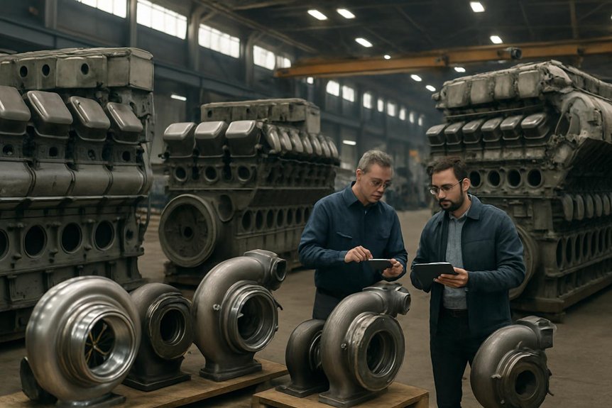
You match EMD 710 turbochargers by full configurationnot cylinder count alone: 8-cylinder engines use smaller approved assemblies, 12-cylinder units use mid-range families, 16-cylinder mainline engines need higher-flow assemblies, and 20-cylinder heavy-haul platforms use the largest approved families. You must verify rating, emissions tier, injectors, controls, lube routing, cooling, gear drive, and approved part numbers. Flange fit doesn’t prove interchangeability, and non-listed turbos can void certification; the details below clarify the limits.

Which EMD 710 engine configurations (8–20 cylinder) use which turbocharger assemblies, and what are the interchangeability limits in locomotives?

The EMD 710 family covers 8–20 cylinder locomotive prime movers with multiple turbocharger assemblies tailored to duty cycles. Railroads typically mate 8–, 12–, 16– and 20–cylinder 710 engines with specific turbo part families to balance fuel efficiency, emissions, and reliability in mainline and heavy-haul service. Interchangeability limits are driven by emissions kits, gear ratios, and control software rather than simple flange compatibility, so engineers must treat turbo swaps as engineering changes, not parts substitutions.

In locomotives, each 710 turbocharger assembly is matched to airflow, backpressure, and thermal loads for its cylinder count and rating band. Swapping to a different turbo model can affect horsepower, NOx compliance, and wheel-slip behavior, even when the hardware mounts correctly. Procurement teams therefore need configuration-level visibility: engine model, tier level, railroad option kits, and approved turbo part numbers.

Locomotive fleets often carry several generations of 710 engines, from early Dash-2 style units to modern Tier 2 and beyond. Managing turbocharger interchangeability across these fleets requires structured asset data and a clear policy for upgrades versus like-for-like replacements. Your blog can guide readers through these practical decisions, highlighting common pitfalls and best practices for EMD fleets.

Key Takeaways

  • EMD 710 turbo matching depends on cylinder count, horsepower rating, emissions tier, duty cycle, and certified equipment package.
  • 8-cylinder 710 engines use smaller turbo assemblies for switching service, lower airflow demand, and controlled exhaust temperatures.
  • 12-cylinder engines use mid-range turbo families, while 16-cylinder engines require higher-flow assemblies for regional and mainline freight duty.
  • 20-cylinder 710 engines use the largest approved turbo families for heavy-haul operation, cooling demand, alternator load, and thermal margin.
  • Turbo interchangeability cannot rely on flange fit; approved part numbers, controls, lube circuits, cooling, backpressure, and emissions compliance must match.

Understanding EMD 710 Engine Configurations in Locomotives

Understanding EMD 710 Engine Configurations in Locomotives

You define modern EMD 710 engine configurations by cylinder count, rating band, emissions tier, and approved turbocharger assembly. Each 8-, 12-, 16-, and 20-cylinder layout supports specific locomotive roles, from switcher duty to heavy-haul mainline service. As fleets age, you must track platform changes, option kits, and certification limits before approving upgrades or interchangeability.

What defines modern EMD 710 engine configurations

Modern EMD 710 engine configurations use a two-stroke, V-type diesel architecture built for locomotive duty. You evaluate them by cylinder count, displacement, rating band, and certified equipment package, not by block size alone. Each bank shares scavenging, exhaust, lube, and cooling requirements that shape approved component choices.

You’ll see 8-, 12-16-, and 20-cylinder variants across locomotive fleets. Smaller 8-cylinder units support lower horsepower requirements where compact packaging matters. The 12-cylinder format raises output while controlling fuel use and thermal stress. A 16-cylinder 710 often serves as the standard high-horsepower road configuration. Larger 20-cylinder versions deliver maximum output where axle loading, cooling capacity, and alternator demand justify the package. Ratings vary with injector settings, turbo matching, controls, and emissions certification, so you should verify the complete locomotive configuration before planning work.

Locomotive roles for each 710 cylinder count

Because duty cycle drives airflow demand, each EMD 710 cylinder count fits specific locomotive roles and turbocharger requirements. You typically see 8-cylinder units in switching service, where frequent throttle changes demand fast response, stable low-speed combustion, and controlled exhaust temperatures.

Regional freight often uses 12-cylinder configurations for balanced horsepower, fuel economy, and axle-loading limits. You’ll match turbocharger assemblies to moderate continuous load, not maximum heavy-haul output.

Mainline freight commonly relies on 16-cylinder EMD 710 engine configurations, where sustained horsepower requires higher airflow, validated backpressure, and approved rating bands. Procurement teams must verify part numbers, gear drives, and emissions files before substitution.

Heavy-haul units may use 20-cylinder platforms for maximum tractive power. Here, emd 710 turbocharger interchangeability narrows sharply because thermal loading, certification, and control calibration leave little tolerance.

Evolution of the 710 platform in rail fleets

As rail fleets evolved, the 710 platform moved from early 710G configurations toward electronically controlled Tier 2 and later emissions packages. You now manage EMD 710 engine configurations by generation, rating band, and approved turbocharger assemblies.

  1. Early 710G units rely more on mechanical governing, fixed calibration, and turbo matching by horsepower class.
  2. Later 12-, 16-, and 20-cylinder fleets add electronic controls that coordinate fuel delivery, boost, and protection logic.
  3. Tier 2+ packages tighten NOx and particulate compliance, so turbo changes must preserve certified airflow and backpressure limits.
  4. Modern overhaul planning treats locomotive prime mover upgrades as configuration changes, not simple component swaps.

You’ll reduce risk by tracking engine model, software, emissions kit, gear train, and approved turbo part family together.

Turbocharger Assemblies Matched to EMD 710 Engine Configurations

Turbocharger Assemblies Matched to EMD 710 Engine Configurations

You match turbocharger assemblies to EMD 710 engine configurations by cylinder count, rating band, and approved duty profile. Each turbo must support the required airflow, boost response, exhaust energy, and thermal margin for locomotive service. You can’t treat interchangeability as simple fitment; emissions certification, drive gearing, and control settings set the limits.

Mapping turbos to EMD 710 engine configurations

When mapping turbocharger assemblies to EMD 710 engine configurations, start with cylinder count, rating band, and emissions tier. You’ll avoid treating turbo selection as simple flange matching during locomotive prime mover upgrades.

  1. 8-cylinder 710: Match smaller turbocharger assemblies to lower airflow demand, lighter duty cycles, and approved horsepower ratings.
  2. 12-cylinder 710: Select mid-range turbo families aligned with commuter, road-switcher, or medium-haul locomotive service.
  3. 16-cylinder 710: Use higher-flow assemblies matched to common mainline ratings, Tier kits, and railroad-specific control settings.
  4. 20-cylinder 710: Reserve the largest approved turbo families for maximum exhaust energy, heavy-haul loading, and thermal margin.

You should verify engine model, software, gear drive, and emissions certification before approving substitutions. That’s how you control EMD 710 turbocharger interchangeability risks.

Key turbocharger design features for locomotive duty

Correct turbo selection also depends on design features that support locomotive duty. You need EMD 710 engine configurations matched to turbocharger assemblies with the right clutch, gas path, and cooling provisions. The integral clutch matters because the turbo must support low-speed scavenging before exhaust energy rises. It lets gear-driven assist transfer to exhaust-driven operation without unstable airflow during throttle changes.

After combustion energy increases, you rely on exhaust-driven operation for efficient boost under sustained load. This supports constant-speed locomotive operation, where engine rpm follows notch settings while traction demand changes. Aftercooling then controls charge-air temperature, protecting pistons, liners, valves, and emissions calibration. You also reduce thermal stress during variable-load service, including grades and dynamic dispatch cycles. Treat these features as approval criteria, not optional preferences.

Rating bands and airflow requirements by cylinder count

Because each 710 cylinder count carries a different horsepower bandturbocharger assemblies must match actual combustion air demand. You size the turbo around fuel rate, exhaust energy, altitude margin, and emissions limits for EMD 710 engine configurations.

  1. 8-cylinder units: You need controlled boost and conservative compressor flow, protecting low-load response and thermal limits.
  2. 12-cylinder units: You balance higher airflow with turbine geometry that supports transient locomotive duty without overspeed.
  3. 16-cylinder units: You match compressor maps to common mainline ratings, fuel burn targets, and certified NOx performance.
  4. 20-cylinder units: You require larger flow capacity, stronger turbine energy handling, and verified cooling capability.

Treat each rating band as a certified system. Don’t interchange turbos unless gearing, controls, lube circuits, and approvals align.

Interchangeability Limits in Locomotive Applications

Interchangeability Limits in Locomotive Applications

You can’t treat flange fit as true interchangeability in EMD 710 locomotive turbocharger assemblies. Emissions certification, rating bands, and approved part numbers define whether a turbo swap stays compliant. Control software, overspeed protection, and thermal limits must match the locomotive’s configuration before release to service.

Mechanical compatibility versus true interchangeability

Although a turbocharger may bolt onto an EMD 710 housing, that doesn’t make it truly interchangeable. You must validate the full EMD 710 engine configurations before approving any swap.

  1. Check drive gear alignment. Mismatched gearing changes rotor speed, load response, and accessory train stress.
  2. Verify lube oil circuits. Incorrect flow or drain routing can starve bearings during locomotive duty cycles.
  3. Confirm cooling and sealing interfaces. Small deviations can raise thermal loading, leakage risk, and exhaust backpressure.
  4. Assess structural limits. Different turbocharger assemblies can impose loads beyond approved frame, bracket, or housing capacity.

Treat EMD 710 turbocharger interchangeability as a controlled engineering change, not a visual match. Mikura International helps you compare part numbers, configuration records, and approved locomotive prime mover upgrades before downtime becomes expensive.

Emissions and certification constraints on turbo swaps

Mechanical fit is only one approval gate; emissions certification often sets the harder limit. For EMD 710 engine configurations, you must verify the certified emissions kit before changing turbocharger assembliesTier documentation can define the turbo as a regulated component, tied to injectors, timing, exhaust hardware, and rating.

Certification data matters because airflow and backpressure influence NOx, particulates, smoke, and fuel maps. You can’t treat EMD 710 turbocharger interchangeability as valid just because the casing, flange, and drive match. A non-listed turbo may void the locomotive’s certified configuration and require revalidation.

Procurement teams should confirm engine model, horsepower rating, Tier level, kit number, and approved part list. Mikura International helps you align locomotive prime mover upgrades with documented compliance, reducing audit exposure and costly rework.

Control system and protection logic impacts

Beyond physical fit, control calibration often defines the real interchangeability limit. With EMD 710 engine configurations, you can’t treat turbocharger assemblies as isolated hardware.

  1. Governor settings set fuel response against expected boost. Change the turbo, and you may create smoke, lag, or overspeed risk.
  2. ECU maps define air-fuel limits, timing, and load response. Incorrect mapping can raise exhaust temperature and reduce component life.
  3. Protection thresholds monitor boost, airbox pressure, lube oil, and temperature. Mismatched signals may trigger nuisance shutdowns or miss real faults.
  4. Approved logic supports emissions certification and reliability records. Uncontrolled EMD 710 turbocharger interchangeability can compromise compliance, horsepower, and wheel-slip behavior.

Therefore, you should verify software, governor setup, and protection logic before approving locomotive prime mover upgrades.

Operational Impacts of Turbocharger Choices in Rail Service

You balance horsepower responsefuel burn, and thermal loading when you change turbocharger assemblies in EMD 710 rail service. You can’t treat reliability separately from configuration approval, because mismatch risks bearing distress, surge, emissions issues, and repeat failures. You gain lifecycle cost control when you standardize approved assemblies by engine rating, duty cycle, and fleet policy.

Performance trade‑offs when changing turbocharger assemblies

When you change turbocharger assemblies on the same EMD 710 locomotive prime mover, you also change its air delivery curve. For EMD 710 engine configurations, that affects how each cylinder count reaches rated load.

  1. Throttle response: You may gain low-speed boost, but you can sacrifice high-notch breathing if the match is wrong.
  2. Fuel consumption: You’ll burn more fuel when boost lags, because racks open before airflow supports combustion.
  3. Smoke levels: You can create visible smoke during load pickup when air-fuel balance falls outside approved calibration limits.
  4. Altitude capability: You’ll protect horsepower better at elevation with the correct assembly, but mismatched units can raise exhaust temperature.

Treat every turbo change as a configuration-controlled locomotive prime mover upgrade, not a simple parts swap.

Reliability, maintenance, and failure modes

Because each turbocharger assembly runs within a defined air, heat, and speed envelope, reliability depends on configuration control. With EMD 710 engine configurations, you prevent avoidable failures by matching inspections to cylinder count, rating, and approved turbocharger assemblies.

Bearing failures often trace to oil contamination, low pressure, or overspeed after an incorrect match. Housing distortion can follow excessive exhaust temperature, poor mounting alignment, or operation outside the certified rating band. Screen plugging restricts airflow and raises thermal loading, so you need configuration-specific cleaning intervals and records.

Treat every turbo change as a controlled maintenance event, not a simple swap. Verify lube supply, drain routing, drive gear condition, mounting hardware, and software settings. When you follow approved limits, you reduce repeat removals and protect locomotive prime mover availability.

Lifecycle cost and fleet standardization benefits

Reliability gains compound when turbocharger choices become fleet standards, not one-off maintenance decisions. You control lifecycle cost better when EMD 710 engine configurations share approved turbocharger assemblies by cylinder count, rating band, and emissions tier. That discipline matters across mixed 8-, 12-, 16-, and 20-cylinder locomotive fleets.

  1. Standardize approved part families, and you reduce slow-moving inventory without risking EMD 710 turbocharger interchangeability limits.
  2. Align training by configuration, so mechanics recognize mounting, gear drive, lube, and cooling differences faster.
  3. Track locomotive prime mover upgrades against certified turbo numbers, because emissions compliance can’t rely on flange fit.
  4. Plan replacements through configuration data, and you cut downtime from wrong assemblies, missing kits, or software mismatches.

Mikura International supports these standards with configuration-focused parts expertise.

Practical Guidance for Engineers and Procurement Specialists

Practical Guidance for Engineers and Procurement Specialists

You should start with a verified register of EMD 710 engine configurations, including cylinder count, rating, tier, and approved turbocharger assemblies. Then, you can separate like-for-like replacements from upgrade candidates using reliability, emissions, and lifecycle-cost criteria. Finally, you’ll reduce interchangeability risk by aligning changes with OEM data, qualified rebuilders, and documented railroad standards.

Building a configuration register for EMD 710 engine configurations

disciplined configuration register gives your team control over EMD 710 engine configurations across mixed locomotive fleets. You prevent unauthorized turbocharger assemblies from entering service by tying every part decision to verified locomotive data.

  1. Record engine model, cylinder count, horsepower rating, and locomotive number.
  2. Capture emissions tier, certification kit, and any railroad-specific option package.
  3. List approved turbo part numbers, supersessions, serial numbers, and installation dates.
  4. Track control software versions, calibration files, and governed speed settings.

Use the register during planning, purchasing, overhaul, and failure analysis. It helps you confirm EMD 710 turbocharger interchangeability before materials leave inventory. Standard fields also support audits, warranty reviews, and emissions documentation. At Mikura International, we treat this record as a control document, not an informal parts list.

Decision framework for upgrades versus like‑for‑like replacement

When should your team upgrade turbocharger assemblies instead of ordering like-for-like replacements? Start with emissions targets. If EMD 710 engine configurations must maintain certified Tier performance, don’t change turbo families without approved configuration evidence.

Next, quantify fuel savings potential against route profile, notch usage, and expected thermal margin. You should upgrade only when airflow and backpressure changes support rated horsepower without raising exhaust temperature risk.

Then, review reliability history by part number, failure mode, and cylinder configuration. Repeated bearing, seal, or turbine damage may justify an engineered upgrade, not another identical replacement.

Finally, test the capital budget against lifecycle value. A like-for-like turbocharger assembly fits urgent outage recovery and fleet standardization. An upgrade fits planned overhaul windows, documented compliance needs, and measurable reliability or fuel-burn improvement.

Collaborating with OEMs and rebuilders for safe interchangeability

Before approving EMD 710 turbocharger interchangeability, verify the proposed assembly against OEM configuration dataqualified rebuilder records, and your locomotive’s certified emissions file. For EMD 710 engine configurations, don’t treat matching flanges as approval.

  1. Confirm cylinder count, horsepower rating, gear drive, lube routing, cooling interfaces, and control software revision.
  2. Require qualified rebuild shops to document clearances, balance reports, material substitutions, actuator settings, and serialized build history.
  3. Run controlled field testing before fleet release, including boost, exhaust temperature, smoke, fuel rate, and fault-code trending.
  4. Keep procurement tied to approved part numbers, emissions tier, and railroad option kits.

Mikura International supports these checks with configuration-focused sourcing and transparent records. You’ll reduce failures, protect compliance, and avoid costly locomotive downtime.

Frequently Asked Questions

Which Turbocharger Assemblies Are Commonly Used on 16-Cylinder EMD 710 Locomotive Engines?

Like a matched compressor wheel to its scroll, you’ll typically see EMD 710 16-cylinder locomotives using EMD turbocharger assemblies from the 710G/GT series, matched by horsepower rating, emissions tier, and control package. You shouldn’t select by cylinder count alone. You’ll need the engine model, rating, gear arrangement, lube and cooling connections, software calibration, and certified part number before approving any replacement or locomotive prime mover upgrade.

How Much Flexibility Do Railroads Have to Interchange Turbochargers Across EMD 710 Configurations?

You have limited flexibility. You can’t treat EMD 710 turbochargers as simple swap parts across 8-, 12-, 16-, and 20-cylinder configurations. You must match airflow, gear drive, mounting, lube circuits, controls, emissions certification, and rating band. Even when a turbocharger assembly physically fits, it may violate Tier compliance or overload components. Use approved part numbers, configuration records, and engineering review before any substitution to protect reliability, fuel burn, and warranty.

What Are the Main Risks of Installing a Non-Approved EMD 710 Turbocharger?

Like a hidden crack in rail, a non-approved EMD 710 turbocharger can turn minor mismatch into costly failure. You risk wrong airflow, excess backpressure, high exhaust temperatures, bearing distress, and piston damage. You can also lose emissions certification, upset control calibration, reduce horsepower, raise fuel burn, and trigger wheel-slip issues. If mounting, gearing, lube, or cooling don’t match, you’ve made an unsafe engineering change, not a replacement for your locomotive fleet.

Can Rebuilt Turbocharger Assemblies Support Certified EMD 710 Emissions Compliance?

Yes, you can use rebuilt turbocharger assemblies to support certified EMD 710 emissions compliance, but only when they match the approved configuration. You need the correct part family, nozzle area, gear ratio, actuator setup, and documented overhaul standard. Don’t treat a rebuild as a generic substitute. Your records should tie the turbo to the engine model, emissions kit, calibration, and test evidence, so audits and performance checks remain defensible.

What Records Should Procurement Teams Keep for EMD 710 Turbocharger Traceability?

Cover your bases by keeping engine serial numberEMD 710 configuration, cylinder count, horsepower rating, emissions tierapproved turbocharger part number, serial number, rebuild status, and certification documents. You should also record installation date, locomotive number, software level, gear ratio, lube and cooling connections, supplier certificates, test reports, and removal reason. Don’t treat these as paperwork; they protect compliance, warranty, reliability, and future procurement decisions across your fleet.

How the EMD 710 Turbocharger Maps Improve Duty Performance

How the EMD 710 Turbocharger Maps Improve Duty Performance

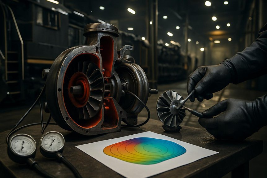
You use EMD 710 compressor and turbine maps to track corrected airflow, pressure ratio, shaft speed, surge margin, exhaust energy, backpressure, and temperature across real notch cycles. The compressor map shows whether boost stays stable during idle recovery, switching, notch-up, and full load. The turbine map shows whether exhaust flow drives boost efficiently without excess heat or scavenging restriction. Together, they (EMD 710 Turbocharger Maps) predict smoke, fuel burn, thermal stress, response lag, reliability, and lifecycle cost across each duty-cycle condition ahead.

How do turbine and compressor maps for the EMD 710 turbocharger influence locomotive duty-cycle performance?

The turbine and compressor maps of the EMD 710 turbocharger determine how effectively the engine breathes across idle, notch changes, and sustained load. In locomotive service, they shape boost, exhaust energy recovery, and transient response, which directly affect tractive effort, fuel use, smoke, and thermal limits.

For rail engineers, the key is matching the turbocharger operating point to the locomotive duty cycle. A compressor map shows where the turbo can deliver stable airflow without surge or excessive discharge temperature. A turbine map shows whether exhaust energy can drive the compressor efficiently at low and high engine loads. Together, they define how well the EMD 710 responds during acceleration, switching, and long-haul running.

For procurement specialists, these maps matter because they influence reliability, maintenance intervals, and life-cycle cost. A poorly matched turbocharger can increase overfueling, lag, fouling, and heat stress in locomotive service. A well-matched unit supports cleaner combustion, better fuel economy, and more consistent performance across changing grades and ambient conditions.

Key Takeaways

  • EMD 710 turbocharger maps verify airflow, pressure ratio, and surge margin across idle, notch changes, and full-load operation.
  • Compressor maps show whether boost and air mass flow remain stable during low-flow events, switching, and rapid throttle commands.
  • Turbine maps reveal how exhaust energy, backpressure, and efficiency affect scavenging, smoke control, and thermal loading.
  • Poor turbine-compressor matching causes boost lag, rich running, higher exhaust temperatures, fuel penalty, and uneven tractive effort.
  • Map-based duty-cycle analysis supports procurement, maintenance intervals, cleaning schedules, reliability planning, and total lifecycle cost control.

EMD 710 Turbocharging in Locomotives

EMD 710 Turbocharging in Locomotives | EMD 710 Turbocharger Maps

You use EMD 710 turbocharger maps to verify airflow, pressure ratio, and surge margin across each locomotive notch. As load changes, you’re asking the turbocharger to match boost demand faster than steady-state test data suggests. Rail duty cycles stress the match harder because grades, throttle transitions, and thermal limits shift engine breathing continuously.

EMD 710 turbocharger maps and engine breathing

The EMD 710’s two-stroke cycle depends on controlled scavenging air at every locomotive load band. You use emd 710 turbocharger maps to verify that airflow supports cylinder clearing, charge density, and combustion stability. Because the engine fires every revolution, weak boost quickly raises smoke, exhaust temperature, and fuel penalty.

Load bandAirflow needMap concern
Idle/low loadStable scavengingSurge margin
Mid loadClean combustionPressure ratio
High loadThermal controlCompressor flow

You should read each operating point against compressor flow and turbine energy lines. That comparison shows whether the turbocharger can move enough air without overspeed, surge, or high discharge temperature. In locomotive service, this breathing margin protects liners, valves, and aftercooler performance under sustained duty.

Locomotive notch changes and boost demand

After confirming engine breathing marginsnotch response shows how quickly the EMD 710 converts fuel demand into stable boost. You see this during rapid throttle changes, when rack position increases before airflow fully catches up. Exhaust energy rises, turbine speed accelerates, and compressor flow must move rightward without crossing unstable regions.

You evaluate EMD 710 turbocharger maps by tracking pressure ratio, corrected flow, and speed during each notch step. A strong match preserves compressor surge margin while building boost fast enough to limit smoke and exhaust temperature. If the turbine efficiency map shows weak energy conversion at that point, boost lags and combustion runs rich. That lag affects tractive effort, fuel rate, and thermal loading. For procurement, you need map evidence that the turbocharger handles notch transients, not just rated load.

Why rail duty cycles are harder than steady-state testing

While steady-state tests hold speed and load nearly constant, rail service forces the EMD 710 through sharper operating changes. You see this when switching demands rapid notch cycling, climbing sustains high exhaust energy, and cruising holds moderate airflow for hours. Bench data can miss these transitions because it averages boost, temperature, and shaft-speed behavior.

In service, you’re managing moving operating points across compressor and turbine maps. A turbine efficiency map helps you judge whether exhaust energy supports boost during acceleration without excess backpressure at load. If matching is weak, you’ll see slower notch response, higher smoke, hotter components, and reduced locomotive duty cycle performance. That’s why EMD 710 turbocharger maps must be reviewed against real routes, tonnage, grades, ambient conditions, and maintenance condition, not only rated-point test results.

Compressor Map and Locomotive Airflow

Compressor Map and Locomotive Airflow

You use the compressor map to verify stable airflow across idle, notch changes, and full-load EMD 710 operation. You’ll protect compressor surge margin by checking low-speed response against required boost and air mass flow. You also track discharge temperature because hotter air reduces combustion quality, raises smoke risk, and stresses engine components.

Compressor operating range in locomotive service

Because locomotive loading changes constantly, the compressor map must show a stable airflow zone across idle, notch changeovers, and full-load operation. You use this zone to verify that airflow, pressure ratio, and compressor speed remain aligned with the EMD 710 engine’s fuel demand. That alignment protects locomotive duty cycle performance by supporting clean combustion during switching, climbing, and sustained haul service.

You should read the operating range as a practical envelope, not a laboratory curve. Each point shows whether the turbocharger can supply enough mass flow without pushing discharge temperature or shaft speed beyond acceptable limits. In railroad service, ambient temperature, altitude, filter restriction, and worn components shift those points. Map review helps you predict boost consistency, thermal loading, and maintenance exposure before sourcing or approving replacement hardware.

Surge margin and low-speed response

After defining the compressor operating envelopesurge margin shows how safely the turbocharger handles low-flow locomotive events. In EMD 710 turbocharger maps, you track this margin between the operating line and surge boundary.

During idle recovery, switching, or notch-up commands, airflow can drop while pressure ratio rises. If matching is poor, you push the compressor toward unstable flow. Surge then creates pulsation, boost fluctuation, and slower cylinder air delivery. That response can delay load pickup and stress bearings, seals, and blades.

You should compare expected duty-cycle points against the compressor surge margin, not just rated-load airflow. A wider margin improves low-speed response during transient rail service. However, excessive margin without efficiency can sacrifice useful boost. Mikura International helps you evaluate map data against actual locomotive duty cycle performance.

Discharge temperature and combustion quality

How does compressor efficiency translate into cleaner combustion on an EMD 710 locomotive? You read EMD 710 turbocharger maps to see where airflow stays efficient, dense, and stable under load.

Higher compressor efficiency reduces discharge temperature for a given pressure ratio. Cooler charge air increases oxygen density entering the cylinders. That helps you match injected fuel with available air during notch changes and sustained pulls.

When discharge temperature rises, air density falls and combustion margin tightens. You’ll see more smoke risk, higher exhaust temperature, and slower recovery after load shifts. Fouling or poor map matching pushes the operating point toward hotter regions.

Use compressor map data to compare airflow, pressure ratio, and efficiency islands against your locomotive duty cycle performance. Better alignment supports smoke control, fuel economy, and predictable thermal loading.

Turbine Map and Exhaust Energy Recovery

Turbine Map and Exhaust Energy Recovery

You use the turbine efficiency map to track how changing exhaust flow drives boost across each locomotive notch. In two-stroke EMD 710 service, you can’t ignore backpressure because it affects scavenging, cylinder clearing, and smoke control. At high load, you need efficient exhaust energy recovery to limit thermal stress and protect duty-cycle reliability.

Turbine map behavior under changing exhaust flow

As exhaust mass flow and temperature rise across the locomotive load range, the turbine map shows how effectively the turbocharger converts that energy into compressor drive. You use EMD 710 turbocharger maps to verify speed, flow, and efficiency alignment during duty changes.

Duty pointExhaust energyTurbine response
IdleLow flow, low heatLimited drive, low boost
Notch-upRising pulse energyAccelerates rotor quickly
TransitoryUnsteady flowTracks stable efficiency island
Full loadHigh flow, high heatDelivers rated compressor power

At idle, you expect modest recovery, not high boost. During notch transitions, you need rapid energy capture without overspeed. At full load, the turbine efficiency map confirms sustained power conversion, supporting locomotive duty cycle performance.

Backpressure and scavenging in two-stroke locomotives

Turbine efficiency also affects exhaust backpressure, which directly shapes scavenging in two-stroke EMD 710 locomotives. You need enough pressure drop across the cylinders to clear residual gas before fresh charge enters. If the turbine map restricts flow, backpressure rises, trapped exhaust increases, and oxygen availability falls. That reduces combustion quality during notch changes and sustained pulling.

You evaluate EMD 710 turbocharger maps to confirm the turbine can pass exhaust mass flow without upsetting air balance. Lower restriction supports cleaner cylinder clearing, steadier blower-assisted airflow, and stronger compressor work. Excessive backpressure can also distort port scavenging, raising smoke risk and fuel penalty. When turbine matching aligns with the duty cycle, you protect locomotive duty cycle performance through stable breathing, consistent boost, and measured exhaust energy recovery across operating notches.

High-load efficiency and thermal stress control

Control high-load heat by reading the turbine efficiency map against exhaust mass flow and pressure ratio. You can see where exhaust energy converts into shaft power without excessive backpressure. In EMD 710 turbocharger maps, that high-efficiency island matters during notch 8, long grades, and hot ambient operation.

Efficient turbine operation lowers exhaust manifold temperature, turbine inlet temperature, and cylinder thermal loading. It also helps the compressor maintain target boost with less waste energy. When the operating point moves outside the efficient zone, you’ll see higher heat rejection, slower boost recovery, and greater stress on blades, bearings, seals, and aftercoolers. That stress shortens overhaul intervals.

Use measured exhaust temperature, boost, and fuel rate to validate map matching. Data helps you protect reliability while sustaining locomotive duty cycle performance under maximum load.

Duty-Cycle Effects on Performance

Duty-Cycle Effects on Performance

You see locomotive duty cycle performance change as acceleration, switching, and haulage move the turbocharger across its maps. and track fuel rate, boost, and smoke response to confirm the EMD 710 turbocharger maps match real notch demand. You reduce reliability risk when compressor surge margin and turbine efficiency map data reflect actual railroad conditions.

Acceleration, switching, and haulage scenarios

When a locomotive moves from idle to higher notches, the turbocharger must build boost before fueling exceeds available air. You read EMD 710 turbocharger maps to predict that delay. In switching, short bursts push operating points rapidly across the compressor map. Weak compressor surge margin can make crews feel hesitation, vibration, or uneven loading.

ScenarioOperational feeling
Yard switchingTense, repeated boost recovery
Notch accelerationUrgent airflow demand
Grade entryHeavy thermal rise
Sustained haulageSteady, confident pull

During long sustained pulls, you hold the turbo near a stable island on the turbine efficiency map. Exhaust energy stays consistent, so boost stabilizes and cylinder balance improves. Compare both cases before approval: transient duty exposes response limits, while haulage reveals endurance limits.

Fuel economy and smoke response

After response and endurance limits, fuel burn and smoke show whether the air path truly matches the duty cycle. With EMD 710 turbocharger maps, you compare commanded fuel, boost pressure, airflow, and exhaust temperature at each notch.

Better map matching keeps the compressor operating in efficient islands, so you get denser charge air without excess discharge heat. That improves air-fuel ratio control during acceleration, switching, and sustained haulage. When airflow arrives late, fuel burns rich, cylinders see incomplete combustion, and visible exhaust rises. When the turbine efficiency map matches exhaust energy, you recover more drive power for boost instead of wasting heat. You’ll see lower specific fuel consumption, cleaner stack opacity, and steadier locomotive duty cycle performance across grades, ambient changes, and throttle transitions while preserving available tractive effort.

Reliability under real railroad conditions

Often, real railroad reliability depends on how well the map fit handles contaminated airheat, and rapid notch changes. You see this in EMD 710 turbocharger maps when operating points stay away from surge and overspeed limits.

  1. Fouling: You reduce efficiency loss when compressor flow capacity tolerates dirty filters and airborne dust.
  2. Heat: You protect pistons, valves, and aftercoolers when the turbine efficiency map controls exhaust temperature.
  3. Bearings: You lower thrust load when pressure ratio changes smoothly during notch shifts, not abruptly.
  4. Service life: You extend overhaul intervals when boost, shaft speed, and exhaust energy align with the locomotive duty cycle performance profile.

You can’t remove railroad variability. You can specify map-matched turbochargers that absorb it with stronger compressor surge margin and lower mechanical stress.

Selection and Procurement Considerations

Selection and Procurement Considerations

You should match EMD 710 turbocharger maps to each locomotive mission profile, including switching, grade haul, and sustained notch operation. You’ll need to verify compressor surge margin, turbine efficiency map data, material specifications, and test records before approval. This approach links procurement decisions to maintenance planning, reliability targets, and measurable life-cycle value.

Matching turbo maps to locomotive mission profiles

Match EMD 710 turbocharger maps to the locomotive’s actual mission profile before approving a replacement unit. You’ll reduce mismatch risk when map data reflects real throttle time, load factor, altitude, and ambient temperature.

  1. For yard duty, prioritize compressor surge margin at low airflow and rapid notch changes.
  2. For regional service, balance transient boost response with mid-load fuel efficiency.
  3. For mainline haulage, emphasize stable high-load operation on the turbine efficiency map.
  4. For mixed fleets, compare operating points against recorded duty-cycle histograms before selection.

This approach helps you predict locomotive duty cycle performance with fewer assumptions. You can identify where boost lag, overfueling, exhaust temperature, or fouling may appear. Mikura International supports sourcing decisions with practical application review, not guesswork, for demanding EMD 710 locomotive service conditions.

Specification checks for buyers and engineers

Before approving an EMD 710 replacement turbocharger, procurement teams should request map-based performance data, not only part numbers. You should ask for EMD 710 turbocharger maps showing corrected airflow, pressure ratio, shaft speed, and efficiency islands across expected locomotive notches.

Review compressor surge margin at low-load shifts and high-altitude operation. Check turbine efficiency map data against exhaust temperature, mass flow, and backpressure limits. Require evidence of boost response during notch changes, including acceleration time and smoke-related airflow shortfall. Compare heat rejection, overspeed margin, and discharge temperature with your engine limits. Ask Mikura International for dimensional checks, material specifications, balancing records, and test-stand results. Document acceptable tolerances before purchase, so you can verify performance, not assume interchangeability across demanding rail duty cycles.

Maintenance planning and life-cycle value

When maintenance teams use map data during selection, they can forecast wear risk before it becomes downtime. You use EMD 710 turbocharger maps to link operating points with heat, speed, surge exposure, and fouling sensitivity across locomotive duty cycles.

  1. Compare compressor surge margin against notch transitions, not only rated load.
  2. Check the turbine efficiency map for exhaust energy use during sustained grades.
  3. Track predicted discharge temperature to plan cleaning, inspection, and bearing intervals.
  4. Align replacement specifications with fleet routes, ambient conditions, and load factors.

This approach helps you reduce unplanned removals, smoke events, and fuel penalties. It also supports stronger budget control because you’re buying expected service life, not just hardware. Mikura International helps you evaluate map fit, failure risk, and total ownership cost before procurement.

Frequently Asked Questions

How Does Altitude Affect EMD 710 Turbocharger Map Matching?

Altitude lowers air density, so you push the compressor operating point toward higher pressure ratio and reduced mass flow. That can shrink compressor surge margin, raise discharge temperature, and slow notch response. You’ll also see changed turbine drive because exhaust energy must work harder to maintain boost. When you evaluate EMD 710 turbocharger maps, compare expected route altitude, ambient temperature, load profile, and allowable thermal limits before you source or approve replacements.

Can Fouled Aftercoolers Shift Compressor Operating Points?

Yes, fouled aftercoolers can shift compressor operating points. You’ll see higher charge-air temperature, greater pressure drop, and reduced air density. That forces the EMD 710 turbocharger to work farther right on its compressor map for the same cylinder air demand. You can lose compressor surge margin, raise exhaust temperature, and increase smoke during notch changes. You should inspect pressure differential, outlet temperature, and fouling trends before blaming turbocharger performance alone.

How Often Should Turbocharger Performance Data Be Reviewed?

Like reading smoke signals from the stack, you should review turbocharger performance data monthly, and after major load complaints, overhauls, or aftercooler cleaning. Track boost pressure, exhaust temperature, airbox pressure, turbo speed, and fuel rate by notch. You’ll catch drift before it becomes surge, overfueling, or bearing distress. For EMD 710 turbocharger maps, compare field points against expected compressor surge margin and turbine efficiency trends during scheduled reliability reviews.

Do Seasonal Temperatures Change Surge Risk in Locomotives?

Yes, seasonal temperatures change surge risk in locomotives. You see higher risk in cold dense air if fueling and boost control don’t stay matched. Hot weather can reduce air density, raise exhaust temperatures, and narrow operating margins under load. You should compare EMD 710 turbocharger maps against ambient data, notch profile, and compressor surge margin. That helps you predict unstable airflow, smoke, and thermal stress before reliability suffers.

Can Map Data Help Predict Turbocharger Overhaul Timing?

Yes, you can use map data to flag overhaul timing trends. You compare actual boost, exhaust temperature, shaft speed, and airflow against EMD 710 turbocharger maps. If operating points drift toward lower compressor efficiency, reduced surge margin, or poorer turbine efficiency, you’re seeing fouling, erosion, leakage, or bearing wear. That evidence helps you plan overhaul before smoke, fuel penalty, high thermal stress, or unscheduled locomotive downtime appears.

How the EMD 710 Locomotive Turbocharger Makes Better Power

How the EMD 710 Locomotive Turbocharger Makes Better Power

You can view the EMD 710 locomotive turbocharger as a hybrid scavenging air system. At start, idle, and low notches, engine gearing drives the compressor so the two-stroke cylinders get reliable air before exhaust energy builds. As load rises, the turbine accelerates, the centrifugal clutch unloads the gear drive, and the unit acts like a free turbocharger. Unlike exhaust-only turbos, it improves low-RPM response while preserving high-load efficiency, with more to compare in the details ahead.

How does the EMD 710 locomotive turbocharger’s hybrid drive (gear-assisted at low RPM, free-turbine at high RPM) work compared to conventional locomotive turbochargers?

The EMD 710 locomotive turbocharger’s hybrid drive combines a gear‑driven blower and free turbine in one unit. At low engine speeds, a gear train mechanically drives the compressor, ensuring sufficient scavenging air for the two‑stroke diesel. As exhaust energy rises with load, a centrifugal clutch lets the turbine overrun the gear drive, transitioning the unit to pure turbocharger mode.

This hybrid concept differs from conventional turbochargers that rely only on exhaust energy across the speed range. Traditional turbo systems on medium‑speed locomotive diesels can suffer from low‑RPM boost lag and poorer low‑notch response. The EMD design delivers more immediate air delivery at low notches, while still capturing exhaust energy efficiently at higher throttle settings.

For rail engineers and procurement specialists, this brings tangible benefits in throttle response, fuel economy, and emissions. The design also influences maintenance practices, spare‑parts strategy, and lifecycle costing for 710‑powered locomotive fleets.

Key Takeaways

  • The EMD 710 two-stroke needs continuous pressurized scavenging air during cranking, idle, load changes, and all throttle notches.
  • At low RPM, the turbocharger is gear-driven, making the compressor act like a mechanically assisted blower.
  • As exhaust energy rises, a centrifugal clutch allows the turbine to overrun and transition toward free-turbine operation.
  • At high load, exhaust energy drives the turbo efficiently, reducing mechanical load on the engine gear train.
  • Conventional locomotive turbos rely only on exhaust energy, so low-load boost response is generally weaker than the EMD hybrid system.

Understanding the EMD 710 Engine and Its Turbo Needs

Understanding the EMD 710 Engine and Its Turbo Needs | EMD 710 Locomotive Turbocharger

You start with the EMD 710 locomotive turbocharger because the 710 two-stroke engine needs pressurized air for scavenging. You can’t rely on piston motion alone to clear exhaust and fill cylinders efficiently. EMD’s path from Roots blowers to hybrid turbochargers solved low-speed airflow limits while improving high-load energy recovery.

Two‑Stroke Design of the EMD 710 Locomotive Engine

The EMD 710 two-stroke locomotive engine fires every piston on each crankshaft revolution, so it depends on continuous pressurized air. You’re managing a high-output engine with large displacement per cylinder, not a naturally breathing machine. Each power stroke needs fresh air to enter fast, clear residual exhaust, and support stable combustion.

Because the 710 uses ports and exhaust valves, airflow must arrive with enough pressure and volume at all times. You need that air during cranking, idle, changeover, and every throttle notch. If pressure drops, scavenging weakens, temperatures rise, and combustion quality suffers.

That’s why the emd 710 locomotive turbocharger isn’t just a power adder. It’s part of the engine’s basic breathing system, supporting reliable starts, clean idle, and load response.

Why Locomotive Diesels Depend on Turbocharging for Scavenging

On the 710, scavenging links directly to turbocharger performance. You use intake air to sweep exhaust gases from each cylinder, then refill it with clean charge air. The EMD 710 locomotive turbocharger supplies that air under pressure, so combustion stays stable across load changes.

Scavenging stageWhat air doesWhy it matters
Port openingEnters cylinder fastPushes exhaust out
Cylinder clearingReduces residual gasesProtects combustion quality
Fresh refillBuilds oxygen chargeSupports rated horsepower

Without forced induction, you can’t clear cylinders effectively. Power falls, exhaust temperatures rise, and emissions drift out of control. The emd hybrid turbocharger drive matters because your two-stroke locomotive engine depends on positive airflow, not natural aspiration, to breathe correctly.

From Roots Blowers to Hybrid Turbochargers in EMD Locomotives

As EMD locomotive horsepower increased, simple Roots blowers couldn’t recover enough exhaust energy for efficient operation. You still needed positive scavenging air for the two-stroke cycle, but higher loads demanded better fuel use and thermal efficiency. On earlier EMD 645 engines, turbo-superchargers began bridging that gap by combining mechanical assistance with exhaust-driven boost.

With the 710 platform, you see that concept refined into a hybrid drive. The EMD 710 locomotive turbocharger acts like a blower at low speed, then behaves like a free turbine as exhaust energy rises. This gear‑assisted turbocharger in locomotives gives you dependable low-notch air delivery without sacrificing high-load efficiency. For aging fleets, it offers practical balance: reliable scavenging, improved response, and better energy recovery than a Roots-only arrangement.

Inside the EMD 710 Locomotive Turbocharger Hybrid Drive

Inside the EMD 710 Locomotive Turbocharger Hybrid Drive

You’ll see the EMD 710 locomotive turbocharger center on four critical elements: turbine, compressor, gear train, and clutch. At low RPM and low notches, the gear train drives the compressor to support scavenging air. At higher RPM and notches, the clutch lets exhaust energy take over in free-turbine operation.

Key Components: Turbine, Compressor, Gear Train, and Clutch

Although the assembly looks compact from the outside, the EMD 710 locomotive turbocharger integrates several critical functions in one housing. You’re looking at a turbine wheel, compressor wheelgear train, and clutch arranged to support two-stroke scavenging demands.

Exhaust gas drives the turbine side, while the compressor side delivers pressurized air into the engine’s airbox. Between them, the internal gearing connects the turbocharger shaft to the engine gear system. That mechanical link makes the EMD hybrid turbocharger drive different from conventional exhaust-only designs.

You also need to account for the overrunning, centrifugal clutch. It lets the turbine overrun and decouple the gear drive as exhaust energy increases. This clutch action enables free‑turbine turbocharger operation without forcing the gear train to carry unnecessary load.

Gear‑Assisted Operation at Low RPM and Low Notches

The gear train and clutch matter most when exhaust energy is still low. During starting, idle, and low notches, the EMD 710 locomotive turbocharger can’t depend on turbine power alone. You need positive air delivery before combustion produces strong exhaust flow.

In this range, the crankshaft drives the turbocharger through the gear train. The compressor acts like a mechanically driven blower, not a passive exhaust-driven turbo. You get minimum scavenging pressure and airflow for the two-stroke cylinders, even when fuel rate and exhaust temperature stay low.

This gear-assisted turbocharger in locomotives helps prevent weak scavenging, smoky combustion, and slow throttle response. For your maintenance team, the key checks are gear condition, lubrication quality, clutch behavior, and abnormal drive noise during low-notch operation and idle stability.

Free‑Turbine Operation at High RPM and High Notches

As throttle notches rise and exhaust energy increases, the turbine accelerates beyond gear-driven speed. In the EMD 710 locomotive turbocharger, you’re no longer relying on mechanical assist for airflow. The exhaust stream now supplies enough power to drive the turbine and compressor as a free-running turbocharger.

  1. The turbine overruns the gear train through the centrifugal clutch.
  2. The clutch prevents meaningful back-driving, reducing mechanical drag.
  3. The compressor speed follows exhaust energy, improving high-load air delivery.

You gain efficient scavenging without forcing the engine gear train to carry unnecessary load. That matters in high notches, where fuel rate, cylinder pressure, and thermal stress all rise. With free-turbine turbocharger operation, you convert exhaust energy into boost instead of wasting shaft power through the EMD hybrid turbocharger drive.

How the Hybrid Turbo Transitions Across the Power Range

How the Hybrid Turbo Transitions Across the Power Range

You track the EMD 710 locomotive turbocharger from Notch 1 to Notch 8 by watching airflow demand rise with load. The centrifugal clutch manages mode switching as exhaust energy lets the turbine overrun the gear drive. You protect the engine by controlling pressure ratio, turbo speed, and scavenging stability across each change.

Turbo Behavior From Notch 1 to Notch 8

When a 710-powered locomotive moves from Notch 1 toward Notch 8, the EMD hybrid turbocharger drive steadily shifts work from the gear train to exhaust energy. You see the EMD 710 locomotive turbocharger support scavenging air when engine RPM and exhaust flow remain limited.

  1. Notch 1-2: You’re near idle-to-light load, so mechanical drive supplies most compressor work and stabilizes airbox pressure.
  2. Notch 3-5: You’re in the midrange, where rising fuel rate and exhaust temperature add more turbine contribution.
  3. Notch 6-8: You’re at high load, where free-turbine turbocharger operation dominates and mechanical assistance becomes minimal.

This behavior helps you reduce smoke, sharpen loading response, and protect two-stroke scavenging across varying duty cycles. It’s why gear-assisted turbocharger in locomotives remains practical for heavy rail service.

The Role of the Centrifugal Clutch in Mode Switching

Across the notch range, the centrifugal clutch controls how the hybrid turbo shifts load between the gear train and exhaust turbine. In an EMD 710 locomotive turbocharger, you depend on this clutch to keep low-speed operation positive and predictable. At lower engine RPM, the clutch stays engaged, so the gear train drives the compressor directly. That mechanical input supports scavenging before exhaust energy can sustain free-turbine operation.

As load rises, turbine speed increases and begins to overrun the gear-driven side. The clutch then slips or releases its driving role, letting exhaust energy carry the turbo without forcing torque back through the gears. You get a progressive handoff, not a harsh changeover. That design limits driveline shock, protects components, and avoids noticeable step changes during throttle movement.

Managing Airflow, Pressure Ratio, and Turbo Speed Safely

As the hybrid drive changes from gear-assisted airflow to free-turbine operation, the turbo’s aerodynamics must stay within a safe pressure ratio and speed range. You manage this by keeping the compressor away from surge at low flow and preventing turbine overspeed at high load.

In EMD 710 locomotive turbocharger service, you’re watching how airflow, fuel rate, and exhaust energy rise together across notches.

  1. Check boost pressure against expected load, not just engine RPM.
  2. Track exhaust temperature to spot restriction, overfueling, or weak scavenging.
  3. Monitor turbo speed where sensors or test procedures support it.

If boost climbs too fast, pressure ratio can stress the compressor. If flow lags, surge risk increases. Good inspections, clean air paths, and correct clutch behavior keep transitions controlled.

Hybrid vs Conventional Locomotive Turbochargers – Technical Comparison

Hybrid vs Conventional Locomotive Turbochargers – Technical Comparison

You compare conventional exhaust-driven turbos by how they manage boost before exhaust energy builds. With an EMD 710 locomotive turbocharger, you get gear-assisted scavenging at low notches and free-turbine efficiency at load. You’ll also weigh added clutch, gear train, and maintenance complexity against response, emissions, and lifecycle gains.

Conventional Exhaust‑Driven Turbos on Medium‑Speed Locomotives

Unlike the EMD hybrid arrangement, a conventional exhaust-driven locomotive turbocharger relies entirely on exhaust gas energy. You typically see this layout on four-stroke, medium-speed locomotive engines, where exhaust flow spins the turbine, and the turbine shaft drives the compressor. There’s no gear train assisting boost at low RPM, so air delivery depends on engine load and exhaust temperature.

  1. At low load**, you get limited turbine energy, so boost builds slowly.
  2. At midrange, rising exhaust mass flow improves compressor speed and manifold pressure.
  3. At high load, the turbo operates efficiently, provided the turbine and compressor match the engine duty cycle.

For an EMD 710 locomotive turbocharger comparison, this baseline matters. You’re evaluating response, airflow control, and parts strategy against a simpler, exhaust-only architecture.

Advantages of the EMD 710 Hybrid Drive for Rail Operations

That exhaust-only baseline highlights why the EMD hybrid design performs differently in rail service. With an EMD 710 locomotive turbocharger, you get mechanically supported airflow before exhaust energy peaks. That means stronger low-notch response, steadier scavenging, and cleaner cylinder charging during switching, yard moves, and slow acceleration.

You also reduce the smoke commonly seen when a conventional turbo waits for exhaust velocity. Better air delivery supports more complete combustion, which can help emissions control and fuel efficiency. In cold starts, gear-assisted airflow helps the two-stroke engine clear cylinders and stabilize faster.

As load rises, free-turbine operation lets you recover exhaust energy without sacrificing high-notch breathing. For your fleet, that translates into more consistent traction power, fewer sluggish transitions, and better performance across varied duty cycles.

Trade‑Offs: Complexity, Maintenance, and Failure Modes

Sometimes, the same hybrid hardware that improves low-notch response also adds inspection points. In an EMD 710 locomotive turbocharger, you’re maintaining more than turbine and compressor condition.

  1. Gear train wear: You should watch backlash, tooth pitting, and unusual whine. These point to misalignment, overload, or poor lubrication.
  2. Centrifugal clutch problems: You’ll see slow transition, surging, heat marks, or slipping during notch changes. That can reduce scavenging air.
  3. Spring drive and lubrication issues: You need clean oil flow and correct damping. Contamination can accelerate bearing wear and gear distress.

Conventional exhaust-driven turbos avoid these mechanical drive parts, so inspection scope is narrower. Still, they can lag at low RPM. The hybrid design trades simplicity for controlled low-speed air delivery and stronger operational flexibility.

Practical Implications for Rail Engineers and Procurement Teams

Practical Implications for Rail Engineers and Procurement Teams

You manage EMD 710 locomotive turbocharger performance through disciplined inspections, correct lubrication, and timely clutch and gear-train checks. You can’t separate overhaul, repair, or upgrade choices from duty cycle, failure history, and parts availability. You should evaluate each hybrid turbo decision against downtime risk, fuel performance, emissions goals, and lifecycle cost.

Maintenance Practices for EMD 710 Turbochargers

In day-to-day fleet service, EMD 710 turbocharger maintenance starts with disciplined inspectionsclean lube oil, and verified airflow. You protect the EMD 710 locomotive turbocharger by treating oil quality and air restriction as operating controls, not paperwork.

  1. Check inspection intervals against duty cycle, not calendar dates only. Heavy low-notch service can stress the EMD hybrid turbocharger drive.
  2. Keep lube oil clean, confirm pressure, and test the soak-back pump. It prevents heat soak damage after shutdown.
  3. Inspect inlet screensair filters, and duct sealing. Restricted airflow raises temperatures and reduces scavenging margin.

When you specify parts, match components to the locomotive’s emission kit. Correct screens, seals, and filters preserve calibration, protect bearings, and support reliable gear-assisted turbocharger in locomotives operation.

Overhaul, Repair, and Upgrade Options for Hybrid Turbos

Evaluate overhaul options by matching turbo conditionfleet duty cycle, and lifecycle cost. For an EMD 710 locomotive turbocharger, you’ll usually compare OEM replacementcertified remanufactured assemblies, and component-level repair. Use OEM units when rotor damage, housing distress, or repeated failures make recovery uneconomical. Choose certified remanufactured turbos when you need controlled tolerances, tested performance, and shorter downtime.

Component repairs fit targeted defects, such as seal leakage, bearing wear, or compressor damage. However, hybrid-drive hardware needs careful judgment. During major overhaul, you’ll often replace or upgrade clutch and gear assemblies, because they control gear-assisted turbocharger operation and free-turbine turbocharger operation. Verify backlash, clutch release speed, balance, and oil cleanliness. Mikura International supports practical sourcing decisions with proven locomotive and marine engine parts expertise.

Procurement and Lifecycle Cost Considerations for Fleets

Link hybrid turbo performance directly to fleet economics, because air delivery affects fuel burn, reliability, and locomotive availability. For every EMD 710 locomotive turbocharger purchase, you should compare acquisition cost with measurable operating impactLow-notch scavenging quality changes fuel burn, smoke, and loading response across duty cycles.

  1. Parts pricing: Check clutch, gear train, bearing, seal, turbine, and compressor availability before committing budgets.
  2. Overhaul intervals: Align expected service life with inspection data, oil condition, vibration trends, and duty severity.
  3. Downtime impact: Price lost locomotive availability, rescue moves, missed turns, and shop labor into total ownership cost.

You don’t buy only a turbocharger; you buy air delivery reliability. Mikura International supports that decision with fit-for-purpose parts planning and practical lifecycle guidance.

Frequently Asked Questions

Which Inspection Intervals Suit EMD 710 Locomotive Turbocharger Overhaul Planning?

Treat inspections like track signals guiding overhaul timing. You should check the EMD 710 locomotive turbocharger during scheduled service, with detailed inspections every 92-day cycleborescope and oil analysis at semiannual intervals, and teardown assessment near major engine maintenance. Don’t rely only on hours. Track boost pressure, exhaust temperature, vibration, clutch behavior, and oil contamination. If trends worsen, you should advance overhaul planning before failures create costly downtime for your fleet.

How Should Fleets Store Spare EMD 710 Turbocharger Components?

Store spare EMD 710 turbocharger components clean, dry, sealed, and traceable. You should cap oil and air passages, use VCI packaging, and keep rotors supported to prevent shaft or blade damage. Don’t stack precision housings or clutch parts. Control humidity, temperature swings, and contamination. Rotate inventory by overhaul date, inspect seals periodically, and document part history. You’ll reduce corrosion, imbalance risk, and rushed procurement before scheduled locomotive outages.

What Documentation Should Accompany a Rebuilt 710 Hybrid Turbocharger?

You should receive a rebuild reportparts traceability recordsinspection findingsbalance certificates, clutch and gear train measurements, and test-run data. Include compressor and turbine clearances, bearing checks, torque records, serial numbers, and any replaced component details. You’ll also want warranty terms, preservation instructions, and installation notes. For an EMD 710 locomotive turbocharger, this documentation helps you verify quality, plan maintenance, control risk, and support lifecycle cost decisions.

How Do Turbocharger Failures Affect Locomotive Availability Metrics?

single road failure can remove 3,000–4,400 horsepower from service instantly. You’ll see turbocharger failures hit availability through unscheduled downtime, missed dispatches, and longer shop dwell. If an EMD 710 locomotive turbocharger loses boost, bearing integrity, clutch function, or turbine efficiency, you can’t load the unit reliably. You also risk secondary engine damage. Track failures by mean time between failures, repair cycle time, repeat removals, and ready-for-service percentage.

Which Parts Influence Lifecycle Cost Most During Turbocharger Procurement?

You should focus on rotating assembliesbearings, seals, clutch components, gear train parts, and nozzle or turbine hardware. These parts drive overhaul frequency, failure risk, and downtime exposure. Don’t judge procurement by unit price alone. Check material quality, balance standards, interchangeability, warranty terms, and parts availability. For an EMD 710 locomotive turbocharger, you’ll control lifecycle cost best by sourcing proven components with reliable overhaul support and documentation from Mikura International.

Translate »