

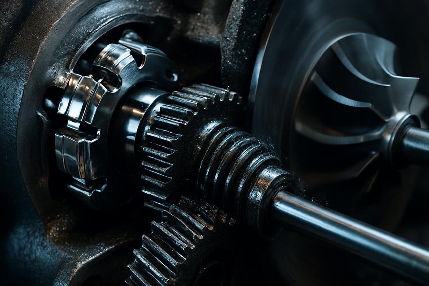
Let’s understand the EMD 710 turbocharger: When you’re operating an EMD 710 locomotive at low loads, the gear train mechanically drives the turbocharger compressor to maintain scavenging pressure. As exhaust energy increases and turbine speed exceeds gear-driven speed, the overrunning clutch disengages automatically—no external control input required. That 3–5% RPM differential threshold governs the handoff, while hysteresis prevents clutch hunting during load cycling. Understanding the full transition mechanics, wear patterns, and maintenance triggers reveals considerably more about keeping this system reliable.
How is clutch engagement/disengagement managed on EMD 710 turbochargers during transition from gear-driven to free-turbine operation in locomotives?
The EMD 710 turbocharger utilizes a specialized overrunning clutch system. This mechanism manages the transition from gear-driven to free-turbine operation. At low loads, the gear train drives the compressor directly. This ensures adequate scavenging air for the two-stroke diesel engine. As load increases, exhaust gas energy rises significantly.
The turbine wheel begins to accelerate rapidly due to this energy. Eventually, the turbine speed exceeds the mechanical gear drive speed. The overrunning clutch then disengages automatically without external control inputs. This freewheeling action prevents mechanical shock and potential damage. It allows the turbocharger to operate efficiently in free-turbine mode.
The system relies on precise differential speed detection for engagement. Lubrication quality critically impacts the clutch engagement reliability. Oil viscosity determines the friction characteristics within the clutch assembly. Proper maintenance ensures smooth transitions during varying locomotive operating conditions. Engineers must monitor these parameters for optimal performance. Procurement specialists should prioritize clutch durability specifications. This design enhances overall locomotive fuel efficiency and reliability.
Key Takeaways
- The overrunning clutch automatically disengages when exhaust-driven turbine speed exceeds gear-driven speed, requiring no external control input to trigger the transition.
- Gear train preload forces press clutch rollers against the inner race during low-speed operation, sustaining mechanical torque delivery to the compressor shaft.
- A 3–5% RPM differential buffer zone separates engagement and disengagement trigger points, preventing clutch hunting between operating modes.
- Oil viscosity directly affects clutch response timing; cold oil slows transitions while elevated temperatures compromise engagement surface oil film support.
- Transition hysteresis, typically a 2–5% differential speed band, prevents compressor surge and mechanical resonance during load cycling events.
Architecture and Operating Modes
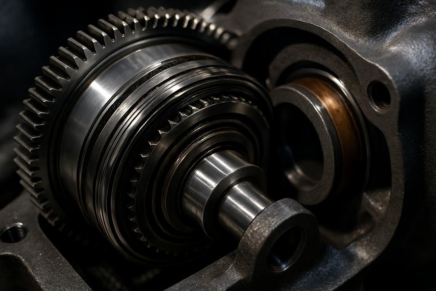
When you work with the EMD 710 turbocharger, you’re managing a two-stroke engine that demands reliable scavenging air across all load conditions. The gear train delivers torque directly to the compressor shaft, ensuring boost pressure before exhaust energy suffices. Understanding this torque path and baseline component layout is essential before examining how the overrunning clutch changes everything.
Two-Stroke Scavenging Needs and Boost
Two-stroke diesel engines can’t scavenge cylinders effectively without sufficient boost pressure at low speeds. Unlike four-stroke engines, they rely entirely on pressurized air to purge exhaust gases and charge cylinders. Without adequate scavenging air, combustion efficiency collapses rapidly.
At idle and low notch positions, exhaust energy remains too weak to spin the turbocharger freely. The EMD 710 turbocharger addresses this directly through its gear-driven assist mechanism. The gear train mechanically drives the compressor, delivering the boost pressure your engine needs immediately.
This assisted boost maintains the minimum air-to-fuel ratio required for clean combustion. It prevents cylinder scavenging failure, reduces thermal stress on pistons, and protects against incomplete combustion. Your engine operates reliably across all load ranges because the assist system eliminates the low-speed boost deficit entirely.
Gear Train and Torque Path
From the crankshaft gear, mechanical torque travels through a dedicated gear train directly to the turbocharger’s compressor wheel. This path ensures your two-stroke engine receives adequate scavenging air at low loads. Each gear stage multiplies rotational speed before reaching the compressor shaft. Torque flows continuously through this mechanical chain during startup and low-power operation.
At the heart of this system sits the overrunning clutch. It connects the gear train to the turbocharger shaft mechanically. When exhaust energy accelerates the turbine beyond gear-driven speed, the clutch releases automatically. Your gear train stops driving the compressor at that precise moment.
Understanding this torque path helps you anticipate switching behavior. Maintaining gear train integrity directly protects compressor response during critical load changes.
EMD 710 turbocharger Baseline Components
Understanding the torque path sets the stage for examining what physically makes it possible.
The EMD 710 turbocharger assembly centers on four interdependent components. Each one directly influences transitory behavior during load changes.
Compressor wheel — draws ambient air and delivers pressurized charge air to engine cylinders.
Turbine wheel — extracts exhaust gas energy, converting it into rotational shaft work.
Rotor shaft — connects both wheels mechanically, transmitting torque between them under all operating conditions.
Overrunning clutch assembly — interfaces the gear-driven assist mechanism with the rotor shaft at the critical transitory threshold.
Shaft support relies on precision journal bearings lubricated under continuous pressurized oil flow. These bearings sustain radial and axial loads across both operating modes.
You’re working with a system where component integration—not individual parts—determines reliability.
Clutch Mechanics and Transition Physics
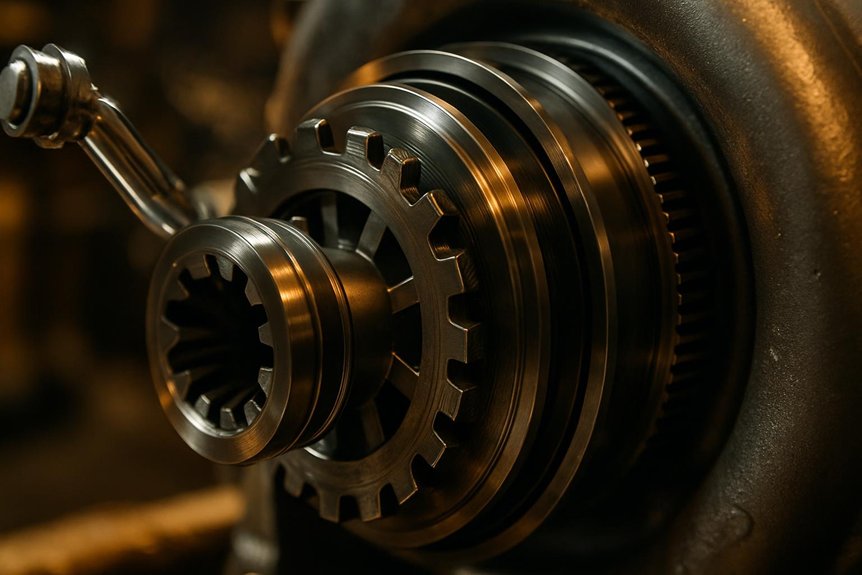
When you examine the EMD 710 turbocharger’s overrunning clutch, geometry and load conditions define its entire operating logic. At low locomotive loads, the gear train mechanically drives the compressor, ensuring adequate scavenging air for the two-stroke diesel cycle. Once exhaust energy accelerates the turbine beyond gear-drive speed, the clutch disengages automatically, moving the system into free-turbine mode.
Overrunning Clutch Geometry and Design
The overrunning clutch inside the EMD 710 turbocharger relies on precisely shaped sprag or roller elements. Each element wedges between inner and outer races at a calculated angle. Wedging angles typically range between 5° and 12°, depending on design. These angles determine engagement torque sensitivity and release speed.
| Element Type | Wedging Angle Range |
|---|---|
| Sprag | 5° – 8° |
| Roller | 8° – 12° |
| Sprag (heavy load) | 6° – 9° |
| Roller (standard) | 9° – 11° |
| High-speed sprag | 5° – 7° |
Tighter angles improve torque transmission during gear-driven assist. Shallower angles enable faster disengagement into free-turbine mode. Your clutch’s geometry directly controls transition smoothness and mechanical load distribution across races.
Engagement Under Low Load Conditions
At low locomotive loads, gear-driven assist keeps the compressor spinning through mechanical torque transfer. The gear train imposes a preload force on the clutch rollers, pressing them firmly against the inner race. This contact stress ensures immediate torque delivery to the compressor shaft. You’re relying on the clutch’s wedging geometry to sustain this mechanical coupling.
Torque flows from the gear drive into the compressor, maintaining adequate scavenging pressure for the two-stroke diesel cycle. Without sufficient exhaust energy, the turbine can’t self-sustain rotation. Mechanical drive compensates directly for this shortfall.
Contact stresses across the roller-race interface remain proportional to transmitted torque. Higher preload forces reduce slip risk but increase wear rates over time. Monitoring these parameters helps you anticipate clutch degradation before it affects locomotive performance.
Disengagement to Free Turbine Operation
As turbine speed climbs beyond the gear drive’s rotational threshold, the overrunning clutch disengages automatically. Differential speed drives this shift—no external control input triggers it. Once exhaust energy accelerates the turbine wheel past mechanical drive speed, the clutch ratchets into freewheeling. Sprags or rollers within the clutch assembly rotate away from their locked position. This removes the mechanical load path between the gear train and the turbocharger shaft.
You’re now operating in free-turbine mode. Exhaust gas enthalpy alone sustains compressor output. Gear-train drag no longer burdens the turbine shaft, improving thermodynamic efficiency noticeably.
Shift happens within milliseconds at the crossover threshold. Abrupt load changes can cause brief re-engagement cycles. Monitoring shaft speed differential helps you identify erratic clutch behavior early. Precise disengagement protects both the gear train and turbocharger bearings from shock loading.
Control, Thresholds, and Hysteresis
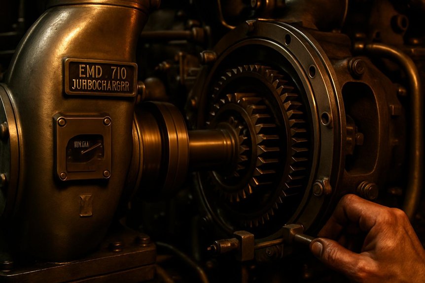
When managing the EMD 710’s assisted turbocharger, you’ll encounter precise speed and pressure thresholds that govern clutch engagement and release. Oil temperature directly influences viscosity, altering friction characteristics and shifting those thresholds unpredictably. You must also account for transition hysteresis—the deliberate lag that prevents surge and mechanical resonance during load cycling.
Speed and Pressure Transition Thresholds
Transition thresholds govern when the overrunning clutch engages or disengages within the EMD 710 turbocharger system. You’re working with two defined bands: gear-driven mode operates below approximately 60–65% of rated turbine RPM. Free-turbine mode activates above that threshold as exhaust energy overtakes mechanical drive speed. Boost pressure mirrors this shift. Below roughly 8–10 psi manifold pressure, the gear train sustains compressor output. Beyond that range, turbine-generated boost becomes self-sustaining. These bands aren’t arbitrary—they’re calibrated to the 710’s two-stroke scavenging requirements. Hysteresis prevents rapid cycling by building a buffer zone between engagement and disengagement points. Typically, a 3–5% RPM differential separates these trigger points. Monitoring both turbine speed and manifold boost simultaneously gives you the clearest picture of transition health.
Oil Temperature and Viscosity Effects
Oil temperature directly controls how the overrunning clutch responds during load changes. Cold oil increases viscosity, slowing clutch response during gear-to-turbine transitions. Elevated temperatures reduce viscosity, compromising the oil film that supports clutch engagement surfaces. You’ll see engagement timing drift when oil operates outside its designed thermal window.
Three critical viscosity-related failure conditions affect clutch performance:
- Cold-soak starts: High-viscosity oil delays roller or sprag element movement, causing sluggish disengagement
- Thermal runaway zones: Thin oil accelerates surface wear on clutch ramps, reducing service life
- Viscosity index breakdown: Degraded oil loses consistent behavior across temperature ranges, introducing engagement unpredictability
Monitoring lube oil temperature during notch transitions gives you early warning of viscosity drift. Maintaining oil within specification directly protects clutch reliability across all locomotive operating conditions.
Surge and Resonance Avoidance Strategies
Viscosity drift doesn’t just affect engagement timing—it sets the stage for compressor surge and mechanical resonance.
You must define clear speed-differential thresholds to control engagement hysteresis. Without defined upper and lower trip points, the clutch hunts between gear-driven and free-turbine modes. That cycling generates resonance in the compressor section.
Your control logic should enforce a hysteresis band—typically 2–5% differential speed—before allowing mode changes. This prevents rapid toggling under fluctuating exhaust energy conditions.
Surge avoidance requires coordinating fuel rack position with compressor inlet conditions during changeover. Rapid load increases outpace scavenging air supply, collapsing pressure ratios and triggering surge.
Monitor inlet manifold pressure continuously. Detect pressure oscillations early to distinguish surge onset from normal transient behavior.
Proper threshold calibration protects both clutch longevity and compressor structural integrity across varying locomotive duty cycles.
Reliability, Monitoring, and Maintenance
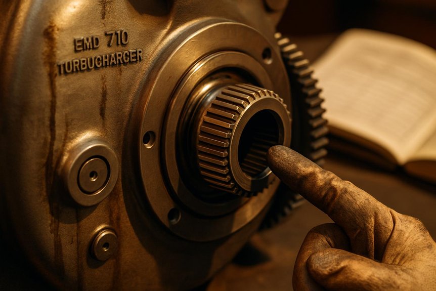
Sustained clutch performance depends on how well you track wear, interpret diagnostic signals, and schedule overhauls. You’ll find that failure modes often surface gradually through measurable indicators before causing operational disruption. Understanding these patterns lets you establish targeted inspection intervals and make informed rebuild decisions.
Wear Patterns and Failure Modes
Wear inside the overrunning clutch assembly follows predictable failure progressions. Identifying these patterns early prevents costly unplanned locomotive downtime. Three primary failure modes demand your attention:
- Sprag spalling: Repeated stress cycling fractures sprag contact surfaces, reducing load transfer capacity progressively.
- Cage wear: Abrasive debris accelerates cage degradation, causing misalignment and erratic engagement behavior.
- Heat discoloration: Thermal overload from insufficient lubrication leaves characteristic blue-black oxidation marks on sprags.
Each failure mode leaves distinct physical evidence during inspection. Spalling generates metallic debris detectable through oil analysis. Cage wear manifests as increased rotational play during manual clutch checks. Discoloration confirms oil starvation events have already compromised clutch metallurgy. Addressing these indicators promptly protects your EMD 710 turbocharger’s operational integrity and switching reliability.
Instrumentation and Diagnostic Techniques
How do you catch clutch degradation before it becomes locomotive downtime? Monitoring three key parameters gives you early warning.
Speed deviation between the gear drive and turbine shaft signals clutch slip. Boost pressure drops indicate incomplete free-turbine engagement. Vibration signatures reveal mechanical wear inside the clutch assembly.
Trending these signals together exposes developing faults before catastrophic failure occurs.
| Parameter | Fault Indication |
|---|---|
| Turbine shaft speed | Abnormal differential vs. gear drive |
| Boost pressure | Below-threshold output at rated load |
| Vibration amplitude | Elevated signatures during phase |
| Oil pressure/temperature | Degraded lubrication affecting engagement |
Correlating all four channels simultaneously accelerates diagnosis meaningfully. You’re not chasing isolated readings—you’re reading system behavior. Mikura International recommends continuous data logging across these channels for fleet-wide reliability programs.
Rebuild and Overhaul Interval Guidelines
Diagnostic data only delivers value when it drives scheduled action. You should align overhaul windows with actual clutch life drivers, not fixed calendar dates. Operational hours, thermal cycling frequency, and oil contamination history all determine true wear progression.
Key interval triggers to track include:
- Accumulated engagement cycles exceeding manufacturer-rated thresholds for your specific duty profile
- Oil analysis results showing metallic particulate spikes indicating ramp wear or roller fatigue
- Transition anomaly logs from prior diagnostic sessions flagging repeated slip events
Waiting for failure introduces unplanned downtime—far more costly than a scheduled overhaul. Mikura International recommends reviewing clutch condition data every major maintenance block. Rebuilding proactively preserves engagement reliability and protects the broader EMD 710 turbocharger assembly from secondary damage.
Procurement and Lifecycle Decisions
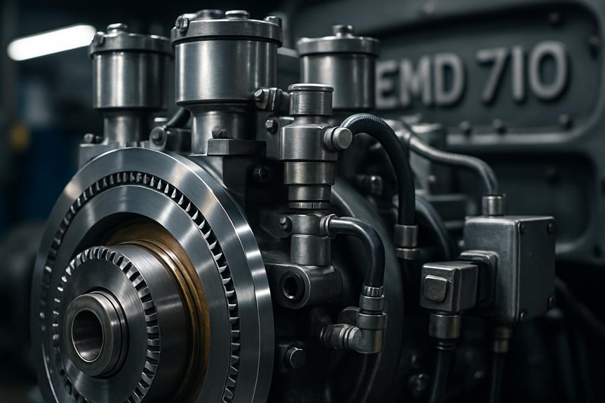
When sourcing components for the EMD 710 turbocharger system, you must prioritize clutch durability ratings over unit price alone. Your spares strategy should account for overrunning clutch wear cycles, retrofit compatibility, and fleet-wide standardization. Total cost of ownership analysis reveals that quality components reduce changeover failures and extend service intervals considerably.
Specification and Spares Strategy
Three critical specification pillars govern clutch procurement for the EMD 710 turbocharger overrunning system.
Clutch ratings, material standards, and interchangeability requirements define your spares strategy’s foundation. Ignoring any pillar creates costly fleet vulnerabilities.
- Clutch ratings: Verify torque capacity against your locomotive’s maximum gear-drive load conditions.
- Material standards: Specify hardened steel ratchet pawls and heat-resistant cage alloys meeting OEM metallurgical grades.
- Interchangeability requirements: Confirm dimensional compatibility across your fleet’s turbocharger variants before bulk procurement.
Mikura International documents all three parameters against original engineering specifications. Cross-referencing part numbers prevents costly fitment errors during overhauls. Standardizing approved spares across your fleet reduces mean-time-to-repair significantly. Establishing minimum stock levels for clutch assemblies prevents unplanned downtime during high-utilization periods. Lifecycle data should inform your reorder thresholds proactively.
EMD 710 turbocharger Retrofit and Upgrade Options
Aging locomotive fleets present retrofit opportunities that directly improve clutch engagement reliability. Upgrade kits are now available for older EMD 710 units. These kits typically include improved overrunning clutch assemblies with tighter manufacturing tolerances. Material improvements address wear patterns common in high-cycle service environments.
Hardened clutch races and upgraded sprag elements extend component lifecycle notably. Revised oil feed geometries improve lubrication consistency during engagement turnovers. You’ll find these upgrades reduce hysteresis variability across repeated load cycles.
Procurement specialists should evaluate kits against original equipment specifications carefully. Compatibility with existing gear-train assemblies must be confirmed before ordering. Mikura International supplies verified retrofit components with full traceability documentation. Sourcing from a qualified supplier eliminates counterfeit risk and ensures dimensional compliance throughout installation.
Total Cost of Ownership Analysis
Retrofit investments only make financial sense when weighed against full lifecycle costs. You’re balancing upfront component costs against operational savings, maintenance complexity, and parts availability. Clutch assembly durability directly affects your total expenditure over time.
Consider these critical cost drivers:
- Clutch replacement frequency: Premature wear from oil degradation or thermal cycling accelerates replacement intervals, compounding maintenance budgets markedly.
- Spare parts inventory: Stocking overrunning clutch components, gear-drive elements, and lubrication system parts ties up capital but prevents costly unplanned downtime.
- Diagnostic investment: Early-detection monitoring tools reduce catastrophic failure risk, offsetting their cost through avoided emergency repairs.
Mikura International helps procurement specialists identify high-durability components that balance performance reliability against inventory carrying costs. Choosing correctly upfront prevents compounding expenses throughout your fleet’s operational life.
Frequently Asked Questions
What Are Typical Indicators of Clutch Slip During Transition?
You’ll typically notice clutch slip through erratic turbocharger speed fluctuations during switchovers. Watch for inconsistent boost pressure readings that don’t track throttle notch progression cleanly. You may also detect abnormal vibration signatures in the turbocharger housing. Elevated oil temperatures near the clutch assembly are another warning sign. Acoustic monitoring often reveals intermittent mechanical chatter during engagement. These indicators demand immediate inspection before they escalate into catastrophic mechanical failure.
How Does Oil Temperature Affect Engagement Reliability in Service?
Oil temperature directly affects clutch engagement reliability in your locomotive’s overrunning clutch assembly. Cold oil increases viscosity, slowing hydraulic response during gear-driven to free-turbine transitions. Excessively hot oil thins out, reducing the film strength needed for controlled engagement. You’ll want oil temperature maintained between 160°F–200°F for consistent clutch performance. Monitor your oil temperature gauges actively during high-load operations to catch thermal drift before it compromises transition reliability.
What Inspection Intervals Are Recommended for Overrunning Clutches?
Ironically, the component that never stops working is the one most teams forget to inspect. You should inspect overrunning clutches every 184,000 km or during scheduled engine teardowns, whichever comes first. Check for sprag fatigue, ramp-surface wear, and cage deformation. You’ll also want to verify oil passage cleanliness during each inspection. Don’t skip post-overhaul functional testing—it confirms proper engagement threshold before the locomotive returns to revenue service.
Can EMD 710 Turbocharger Clutch Components Be Retrofitted to Older Locomotive Models?
Yes, you can retrofit EMD 710 turbocharger clutch components to older locomotive models, but it’s not straightforward. You’ll need to verify gear train compatibility, oil system pressure specifications, and housing dimensions first. Mismatched interfaces cause premature clutch wear or engagement failure. Mikura International’s engineering team can assess your specific locomotive configuration and supply correctly matched components, ensuring reliable shift performance without costly fitment errors.
How Does Altitude or Climate Affect Turbocharger Transition Thresholds in Locomotives?
Altitude and climate directly shift your turbocharger’s shift thresholds. At high elevations, thinner air reduces exhaust energy density, delaying free-turbine mode engagement. Cold climates thicken oil viscosity, slowing clutch response during gear-driven transitions. Hot, humid environments accelerate thermal stress on clutch components. You’ll need to recalibrate your control thresholds and monitor oil temperature closely to maintain reliable EMD 710 turbocharger performance across varying operating conditions.
You may also like to read this – Enhanced algorithm for predictive maintenance to detect turbocharger overspeed in diesel engine rail vehicles.