
Your better locomotive hydraulic dampers create epic rides by converting violent kinetic energy into heat through calibrated oil flow. You get velocity-dependent resistance that suppresses hunting instability while softening impacts from rail joints. Precision-valved pistons and high-strength cylinders manage multi-axial loads far exceeding automotive scales, and digressive force-velocity curves balance wheel-to-rail contact against structural load transfer. Strategic thermal management prevents viscosity fade during extreme duty cycles. The complete engineering story extends well beyond these fundamentals.
How do hydraulic dampers work in locomotive suspension systems?
- Hydraulic dampers in locomotives convert kinetic energy into heat.
- They use fluid flow through calibrated orifices.
- This controls bogie and axle movement.
- It dampens vertical and lateral oscillations.
- It ensures stable wheel-to-rail contact.
- The damper body is robust for heavy loads.
- It withstands harsh environmental conditions.
- A piston moves inside a sealed cylinder.
- It forces oil through precision valves.
- These valves generate velocity-dependent damping force.
- The force resists suspension motion.
- It manages primary and secondary suspension dynamics.
- It reduces yaw, bounce, and pitch.
- This maintains consistent wheel loads.
- The oil is high-viscosity index fluid.
- It resists viscosity changes from temperature.
- Seals prevent leakage under extreme pressures.
- These dampers enhance locomotive safety.
- Minimize dynamic track force variations.
- Reduce wear on wheelsets and bogies.
- Improve ride quality for crew.
- They are vital for heavy-haul operations.
- Ensure reliable traction and braking.
- Extend maintenance intervals.
- They support higher operational speeds.
- Damping curves are tuned for each locomotive class.
- This optimizes performance across speed ranges.
- They also reduce structure-borne noise.
Key Takeaways
- Precision valving generates speed-dependent damping to suppress hunting oscillations and stabilize the locomotive at high speeds.
- Massive oil volume and large stroke absorb severe track impacts while dissipating heat to prevent fade on long runs.
- Digressive force-velocity curves soften high-speed blow-off to protect structure from rail joint shock loads.
- Spherical bearings and robust mounting brackets channel multi-axial forces without inducing seal-wearing side loads.
- Secondary yaw and lateral dampers control body sway through curves for superior ride quality and crew comfort.
Fundamentals of Hydraulic Damping in Locomotives
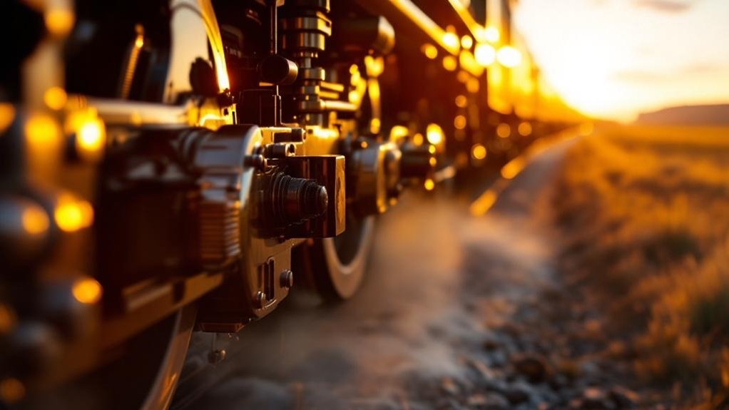
Your locomotive’s suspension needs damping to control bogie oscillations and maintain wheel-rail contact. You’ll find a hydraulic damper works by forcing oil through valves, converting motion energy into heat. Unlike automotive units, these railway bogie dampers handle far greater loads and harsh track environments.
The Need for Damping in Rail Suspension
Because wheel-rail forces create relentless dynamic oscillations, locomotive suspension demands controlled energy dissipation. Without it, you face hunting instability and excessive component wear. Railway bogie dampers directly counter these forces. You need locomotive hydraulic dampers to convert kinetic energy into heat. This process manages vertical and lateral movements precisely. It maintains consistent wheel-to-rail contact for safe traction. You’ll see reduced dynamic track force variations. This protects your wheelsets and bogies from premature wear. It also improves ride quality for your crew. You gain reliable braking and higher operational speeds. Systematic damping prevents derailment risks. It controls yaw, bounce, and pitch motions. Your locomotive’s stability depends on this energy dissipation.
Basic Working Principle of a Hydraulic Damper
Understanding how railway bogie dampers counter those forces starts with a piston displacing oil inside a sealed cylinder. You see kinetic energy convert directly to heat as fluid shears through calibrated passages. This velocity-dependent resistance forms the core of all suspension damping systems, scaling force directly with piston speed. It’s a systematic dissipation process, not storage.
- Your damper generates resistance proportional to velocity, enabling precise locomotive ride control.
- The piston forces oil through restricted orifices, systematically managing energy.
- Internal valving creates a pressure differential, countering bounce and sway.
- This conversion prevents oscillation build-up, stabilizing the carbody immediately.
- You rely on this fluid shear for consistent, speed-dependent force across all operational conditions.
Key Differences from Automotive Dampers
Unlike automotive units, locomotive hydraulic dampers operate at a far larger physical scale and capacity. You see stroke lengths commonly exceeding 200 mm. They dissipate massive kinetic energy from heavy bogies. You rely on their robust, heavy-gauge steel bodies. Their seals withstand much higher internal pressures. They use high-viscosity-index oils for thermal stability. Their mountings manage enormous dynamic load paths. You don’t deal with simple road irregularities. You control violent lateral and vertical rail forces. This demands fundamentally different, industrial-grade engineering. Key divergences define their performance envelope. You can analyze these systematically.
| Feature | Locomotive Damper | Automotive Damper |
|---|---|---|
| Typical Stroke | Often >200 mm | Typically <150 mm |
| Peak Pressure | Very high, extreme duty | Comparatively moderate |
| Fluid Volume | Large for heat dissipation | Relatively small |
| Seal Design | Multi-stage, heavy-duty | Lighter, integrated |
| Mounting Loads | Massive, multi-axial | Lower, primarily axial |
Anatomy of a Locomotive Hydraulic Damper

You’ll examine the cylinder and piston assembly first, as it forms the damper’s core working structure. The valve systems then precisely orchestrate fluid flow to generate the velocity-dependent damping force you need. Finally, you’ll analyze how advanced seals and specific oil specs guarantee consistent performance under extreme railway conditions.
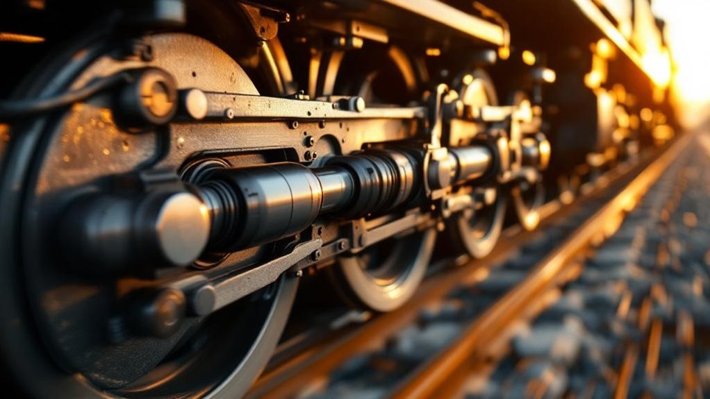
Cylinder and Piston Assembly
A single cylinder and piston assembly forms the damper’s beating heart. You’ll find it houses a high-strength steel cylinder with a hard-chrome-plated bore. Your piston moves within this sealed environment, forcing oil through calibrated routes. Precision clearances stop metal-to-metal contact during operation. This ensures your damper delivers consistent, reliable performance under extreme locomotive loads.
- Your cylinder uses robust steel to withstand high internal pressures.
- Its hard-chrome plating provides a smooth, wear-resistant running surface.
- Wear bands on your piston maintain precise alignment inside the bore.
- Specialized seals prevent fluid bypass around your piston assembly.
- Controlled clearances dictate your damper’s baseline resistance characteristics.
Valve Systems and Damping Force Generation
Valve stacks convert fluid pressure into controlled damping force. You’ll find these shims deflect precisely under oil pressure. Blow-off valves then cap peak forces during extreme shocks. This arrangement generates a digressive curve, softening high-speed inputs. It directly controls locomotive ride control and hunting stability.
| Component | Function | Benefit |
|---|---|---|
| Shim Stack | Progressive deflection under pressure | Tunes velocity-dependent force |
| Blow-off Valve | Port restricts flow at threshold | Prevents damper cavitation |
| Piston Port | Directs oil through stack | Defines initial damping curve |
| Check Valve | Enables asymmetric cycling | Separates rebound from compression |
Sealing Technology and Oil Specifications
While valve stacks generate damping forces, robust sealing and oil specs secure reliability. These two subsystems prevent performance decay from leakage or thermal instability. Your damper’s high-pressure rod seals block oil egress and abrasive ingress. Specialized oil with anti-foam agents and a high viscosity index works from -40°C to +80°C. A built-in oil reserve absorbs thermal expansion, preventing cavitation. This sealed fluid system defines locomotive ride consistency. You count on this triad for every heavy-haul journey, from desert heat to arctic cold.
- Rod seals endure high pressure while blocking water, dust, and chemical contaminants.
- Anti-foam additives instantly collapse bubbles, preserving stable damping force.
- High-viscosity-index oil resists thinning in heat and thickening in cold.
- Thermal expansion is managed by a dedicated compensation volume within the damper body.
- Oil specifications directly shape damper fade resistance and maintenance intervals.
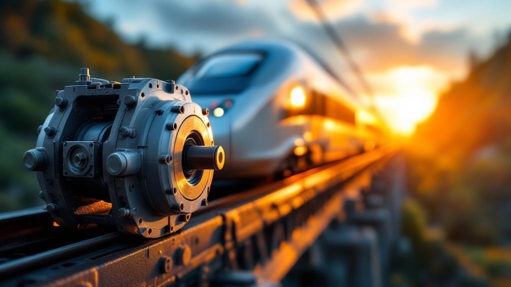
Integration into Locomotive Suspension Architecture
You place primary suspension dampers between the axlebox and bogie frame to control high-frequency track irregularities. You install secondary dampers laterally and vertically between the bogie and locomotive body to manage sway and yaw. These mounting configurations define distinct load paths that isolate force transmission for effective ride control.
Primary Suspension Dampers
Because primary suspension dampers mount directly between the axle-box and bogie frame, they’re the first line of defense against track irregularities. You’ll feel their effect as they control vertical axle hop and lateral guidance forces. This immediate reaction stabilizes hunting oscillations right at the source. Their force-velocity curve is tuned sharply to resist wheel unloading events. You depend on this rigid coupling to maintain consistent wheel-to-rail contact.
- They convert kinetic axle motion into heat through forced high-viscosity oil flow.
- Vertical damping works alongside your coil springs to absorb high-frequency track shocks.
- Lateral damping directly counteracts the conical wheel profile’s natural hunting tendency.
- You secure them through rigid mounting points that define a precise, linear load path.
- Their valve shim stacks open progressively to generate speed-sensitive, digressive resistance.
Secondary Suspension Dampers
Secondary suspension dampers mount between the bogie frame and the locomotive body. You’ll find they integrate lateral dampers to control body sway on curves. Yaw dampers resist bogie rotation, ensuring critical high-speed stability. Sometimes, vertical dampers manage bounce and pitch. This architecture isolates the carriage from track-induced vibrations. It directly improves your ride quality and crew comfort. By precisely tuning damping forces, you maintain consistent wheel loads during operation. The dampers work with air springs to optimize dynamic behavior. Your system reduces structure-borne noise and wear on components. This analytical integration enhances safety across speed ranges.
Mounting Configurations and Load Paths
While controlling motion, locomotive hydraulic dampers transfer substantial forces through their mounting points. You must integrate them carefully into the bogie and body structure. The eyelets incorporate spherical bearings or elastic bushings. These accommodate misalignment during dynamic bogie motions. Mounting brackets must withstand cyclic high forces without fatigue failure. Correct alignment is critical; it eliminates side loads that accelerate seal wear. Analyze these load path factors:
- Spherical bearings permit multi-axis rotation, reducing bending on the rod.
- Elastic bushings isolate vibrations and minimize transmitted structure-borne noise.
- Load paths channel damping forces directly into primary suspension nodes.
- Even slight misalignment induces side loading, leading to premature seal failure.
- Regular visual inspections of mounts and welds prevent catastrophic detachment.
Proper mounting configuration ensures best damper performance and extends maintenance intervals. It’ll protect your investment and ride quality.
Performance Characteristics and Tuning
You start by analyzing force-velocity curves that define damping behavior. You then tune temperature compensation to prevent fade under thermal loads. Finally, you evaluate durability parameters for lifecycle cost optimization.
Damping Force-Velocity Curves
Plotting damping force against piston velocity reveals how locomotive hydraulic dampers manage ride dynamics. You analyze these curves to verify precise, speed-dependent control. A divergent profile dominates because it offers specific advantages for railway bogie dampers and locomotive ride control.
- You gain high damping force at low piston speeds to suppress hunting oscillations and bogie instability.
- You observe force plateau or decrease at higher speeds, softening impact from rail joints and switches.
- You tune the blow-off point to match the locomotive’s unsprung mass and operational track speed.
- You adjust the curve slope to balance critical wheel-to-rail contact against structural load transfer.
- You validate symmetric tension/compression forces for consistent yaw and pitch attitude management.
This systematic tuning within suspension damping systems ensures stability without harshness.
Temperature Compensation and Fade Resistance
Force-velocity curves shift as damper oil heats during operation. You see viscosity drop, which reduces your locomotive ride control force. This fade destabilizes your railway bogie dampers. You need systematic temperature compensation in your suspension damping systems. Quality dampers integrate bimetallic valve discs. These deflect with heat to modify oil flow area. You maintain a consistent damping coefficient despite thinning fluid. Alternatively, your design uses a large internal oil volume. This mass acts as a heat sink to slow temperature rise. For severe-duty cycles, you specify external cooling fins. You might add a remote reservoir for better heat dissipation. These features prevent performance fade on long grades. Your damper’s force output remains stable and predictable.
Durability and Lifecycle Considerations
Before a locomotive damper enters service, manufacturers validate its durability through endurance tests that simulate millions of cycles. You must then consider long-term lifecycle factors. Seal degradation, bushing wear, and oil shear progressively diminish damping performance. You can now leverage condition monitoring to predict failures, not just react to them.
- You analyze seal life to prevent external leakage under high pressures.
- You monitor oil condition because thermal breakdown alters viscosity.
- You check bushing integrity, as wear introduces free play into the load path.
- You use temperature sensors to flag abnormal friction or fade events.
- You deploy pressure transducers for real-time damping force verification.
This systematic approach moves you from fixed schedules to condition-based overhauls, extending service intervals and reducing lifecycle costs.
Selection and Procurement for Rail Engineers
You must first tie damper specs to each locomotive’s loading gauge and duty cycle. Then verify certs like EN 13802 or AAR M-901 for guaranteed ride control. Finally, weigh lifetime costs against supplier record for reconditioning compliance and fleet support.
Specifying Dampers for Locomotive Classes
When specifying locomotive hydraulic dampers, you must analyze the locomotive’s operational profile and suspension requirements. You then define critical parameters to ensure locomotive ride control. This systematic approach prevents hunting instability and excessive wear.
- Calculate the required stroke length from bogie-to-body articulation limits.
- Define damping coefficients for both compression and rebound across speed ranges.
- Specify mounting geometry and load paths to avoid structural fatigue.
- Demand custom valve tuning for velocity-dependent force-velocity curves.
- Consider axle load and track quality to predict damper duty cycles.
Your precision in these specifications directly dictates traction, safety, and crew comfort in heavy-haul service.
Standards and Certification
Because locomotive hydraulic dampers operate under extreme dynamic loads, procurement demands unwavering adherence to rail standards. You’ll specify compliance with EN 13802, AAR M-1003, or UIC 526 at minimum. These standards mandate rigorous type testing protocols. They validate dynamic performance, structural endurance, and environmental resilience. Certification confirms the damper’s design integrity for your specific fleet. You’ll review test reports analytically, verifying force-velocity curves match your hunting stability requirements.
| Standard Body | Key Focus for Dampers |
|---|---|
| EN 13802 | Railway applications; dynamic and endurance testing |
| AAR M-1003 | Quality assurance for North American interchange |
| UIC 526 | International standards for suspension components |
You’ll make sure the supplier’s certification guarantees part interchangeability. This systematic approach eliminates risks from unverified suspension damping systems. It assures consistent locomotive ride control and safety across all operating conditions.
Total Cost of Ownership and Supplier Evaluation
Procurement evaluates locomotive hydraulic dampers through a systematic total cost of ownership (TCO) model. You don’t just compare unit prices. You analyze lifecycle costs from installation to decommissioning. A cheap damper often hides frequent replacement cycles and operational downtime. Instead, you calculate long-term value.
- Assess service life predictions against maintenance schedules to avoid premature failure.
- Verify reconditioning capability because it reduces waste and lowers sustained capital outlay.
- Audit spare parts availability for critical valve and seal kits to prevent extended fleet grounding.
- Quantify technical support responsiveness from suppliers for rapid troubleshooting and engineering feedback.
- Structure performance-based logistics contracts that tie payment to damper reliability metrics, not just delivery.
Frequently Asked Questions
What Causes Hydraulic Damper Fade in Extreme Cold?
In extreme cold, you’ll experience hydraulic damper fade because the oil’s viscosity spikes dramatically. This thickened fluid resists flowing through the calibrated orifices and valve shim stacks that generate damping force. You’ll see delayed piston response, so the damper can’t convert kinetic energy into heat efficiently. The pressure differentials collapse, reducing force output. Your damper momentarily loses its ability to control bogie oscillations until the oil warms from internal shear.
How Do You Detect Internal Seal Leakage Early?
Think of seal leakage as your damper’s silent scream before it goes mute. You catch it early by monitoring the rod for a clinging, wet film that’s more than a whisper. Track performance fade through force-velocity graphs; a sagging curve reveals lost fluid. Regularly inspect the boot for clandestine oil pools. Use thermal imaging to spot a cool zone where damping’s fire dies. These systematic checks let you hear the faintest cry of failure, preventing a total shutdown.
Can Dampers Be Reconditioned After Fluid Contamination?
You can recondition dampers after fluid contamination if you catch the damage early. You’ll first fully disassemble the unit and inspect every internal component. You check for eroded valve seats and scored piston rods. You then replace all seals and flush the contaminated oil completely. You refill it with approved high-viscosity-index fluid. You’ll finally dyno-test it against its original force-velocity curve, ensuring stable damping performance recovers.
How Do Hydraulic Dampers Interact With Air Springs?
Your locomotive’s hydraulic dampers and air springs form an integrated suspension system. Air springs handle static load and primary vertical support, while dampers control dynamic motion. You see this on a heavy-haul EMD SD70ACe, where adjustable dampers precisely manage rebound from air spring compression during curve negotiation. The dampers resist rapid displacement, preventing excessive bounce and pitch. This systematic interaction maintains consistent wheel-rail contact force, optimizing hunting stability across speed ranges without compromising the pneumatic isolation benefits.
What Are the Total Cost Differences Between Reconditioning and Replacement?
You weigh reconditioning’s lower upfront cost against replacement’s longer lifecycle. Reconditioning typically costs 30-50% of a new damper’s price, but you’ll face shorter service intervals and variable quality. Replacement incurs higher initial capital, yet delivers predictable performance, full warranty coverage, and extended maintenance cycles. Your total cost analysis must factor in downtime, labor for changeouts, and reliability risks over the locomotive’s operational life.