
The Critical Role of Mechanical Parameters in Railway Contactors
Railway locomotives depend on sophisticated electro-mechanical switching devices called contactors to manage high-current power distribution across traction motors, braking systems, and auxiliary equipment. These contactors must reliably handle currents exceeding 500 amperes while operating in harsh railway environments characterized by extreme temperature variations, persistent vibration, moisture exposure, and demanding duty cycles. The mechanical parameters governing contact normal load, spring design characteristics, and make/break speed fundamentally determine whether a locomotive’s electrical system operates reliably or experiences catastrophic failure at the worst possible moment.
Understanding how contact normal load and spring design influence contactor endurance represents essential knowledge for rail engineers and procurement specialists responsible for fleet maintenance and capital equipment selection. The relationship between these mechanical parameters and both electrical and mechanical endurance creates optimization challenges that separate well-maintained, reliable locomotives from those experiencing frequent electrical failures and unexpected service interruptions. This comprehensive exploration examines how proper mechanical parameter optimization extends contactor service life, reduces maintenance costs, and improves overall locomotive reliability and safety.
Understanding Contact Normal Load in Railway Contactors
The Fundamental Physics of Contact Pressure and Resistance
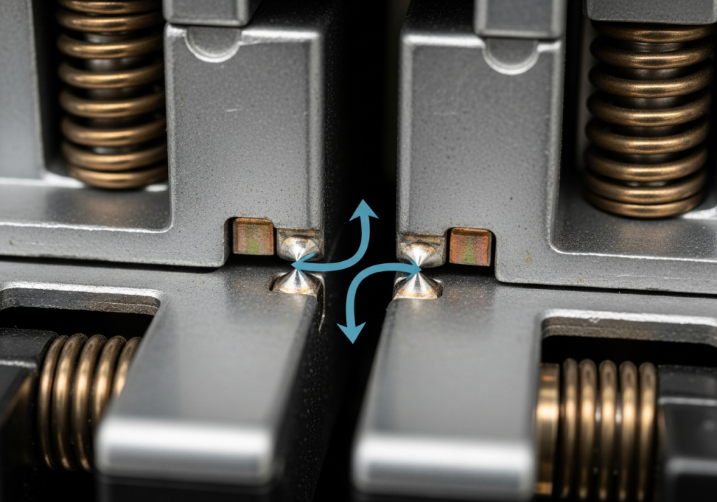
Contact normal load, commonly referred to as contact pressure or contact force, represents the force pressing electrical contact surfaces together during switching operations. This deceptively simple mechanical characteristic profoundly influences electrical performance, thermal behavior, and wear rates in railway contactors. The relationship between contact pressure and electrical contact resistance has been well-established since the early twentieth century through fundamental research in electrical contact physics, particularly work by Ragnar Holm documented in the “Electric Contacts Handbook” that remains relevant to modern applications.
As contact pressure increases, contact resistance decreases following a non-linear relationship rooted in the physics of microscopic contact behavior. When two metallic surfaces meet under load, actual contact occurs only at microscopic high spots called contact spots, creating a constriction in the electrical current path. These constriction spots generate heat proportional to the square of current and inversely proportional to contact area. Higher contact pressure expands the contact area and crushes surface contaminants and films, dramatically reducing contact resistance. This fundamental principle explains why properly maintained contact pressure is absolutely critical for reliable locomotive electrical systems.
In railway locomotive applications, typical contact pressures range from 10 kilograms-force (98 newtons) for lightweight pilot circuits to over 50 kilograms-force (490 newtons) for main traction contactors handling 500+ amperes. The specific pressure required depends on contact material composition, expected current magnitude, frequency of switching operations, and environmental conditions. Indian railway specifications for electromagnetic contactors on electric locomotives mandate maintaining contact pressure within narrow tolerance bands, with specific bolt torque values ensuring consistent pressure application across all contact pairs throughout the contactor’s operational life.
How Contact Pressure Affects Electrical Performance in Locomotive Duty
Contact pressure directly determines whether a locomotive contactor maintains reliable electrical performance or degrades toward failure. When contact pressure is insufficient, several failure modes emerge rapidly. High contact resistance creates localized heating at contact surfaces, potentially exceeding material melting points and causing contacts to weld together in the closed position. This catastrophic failure prevents the contactor from opening, trapping the locomotive in maximum power output with no ability to reduce current or stop the train—an unacceptable safety hazard.
Inadequate contact pressure also allows contact bounce—momentary separation of contacts immediately after they close due to elastic rebound of the mechanical assembly. This bounce creates micro-arcs that cause rapid contact material erosion and pit formation, visible as microscopic craters and material transfer marks. The contact resistance increases as pitting develops, creating a vicious cycle where higher resistance generates more heat, accelerating pit formation and material degradation. Locomotives operating with degraded contact pressure often exhibit erratic motor performance, including sudden loss of power, stuttering acceleration, and inability to maintain consistent speed on grades.
Conversely, excessive contact pressure accelerates spring fatigue and mechanical wear without providing proportional electrical benefits. Beyond approximately 50-60 kilograms-force contact pressure, additional force provides minimal improvement in contact resistance while dramatically increasing stress on spring components and contact carriers. This over-pressure condition shortens mechanical life, increases maintenance requirements, and raises total cost of ownership despite potentially improving short-term electrical performance. Railway maintenance engineers must therefore optimize contact pressure to a specific target value rather than simply maximizing pressure.
Pressure Optimization Techniques for Railway Applications
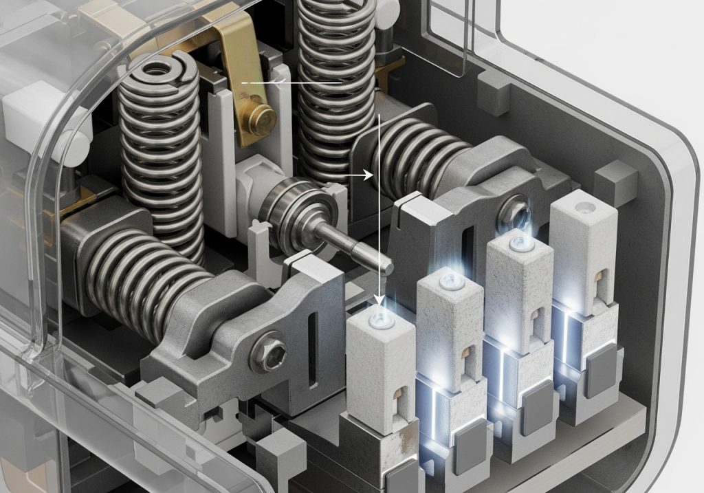
Achieving optimal contact pressure in locomotive contactors requires careful coordination between electromagnetic coil design and mechanical spring preload. The coil, when energized, generates magnetic force that pulls the movable contact assembly toward the stationary contacts. Spring force opposes this motion, and the difference between coil force and spring force determines net contact pressure. Railway contactors are engineered so that at rated coil voltage, the magnetic force exceeds spring force sufficiently to close contacts reliably even if contact resistance is temporarily elevated or spring force has degraded somewhat.
In electro-pneumatic contactors used on some railway locomotives, compressed air pressure supplements or replaces electromagnetic force in achieving contact closure. These pneumatic systems require different optimization approaches, focusing on air pressure regulation, valve timing, and mechanical linkages connecting air cylinders to contact carriers. Maintenance of air system integrity becomes critical—any air leakage reduces available pneumatic force and prevents proper contact pressure, making regular inspection and seal replacement essential for maintaining reliability.
Practical optimization begins with understanding the specific locomotive’s duty cycle and environmental conditions. Heavy-duty freight locomotives operating under maximum load continuously require different contact pressure optimization than lighter commuter locomotives with frequent start-stop cycles. High-humidity environments near coasts or in tropical regions may require higher contact pressure to overcome corrosion film buildup, while dry continental environments tolerate lower pressure. Railway maintenance programs typically establish baseline contact pressure specifications for each locomotive model and verify adherence through resistance testing during periodic maintenance intervals.
Spring Design and Its Impact on Contactor Performance
Spring Mechanics and Material Properties in Railway Contactors
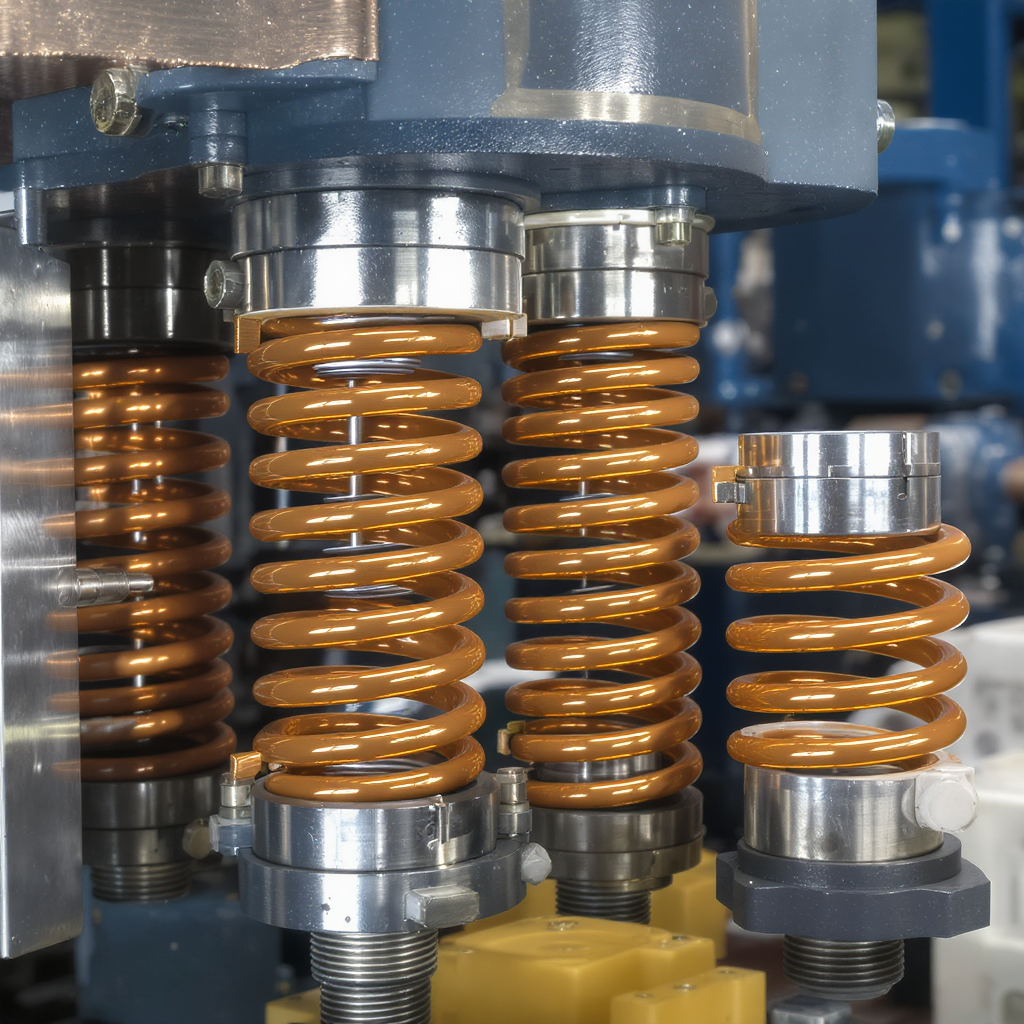
Spring systems represent the mechanical heart of locomotive contactors, serving multiple interdependent functions simultaneously. The contact spring maintains pressure on electrical contacts throughout switching cycles. The reaction spring resists electromagnetic closing force and helps control closing speed. The return spring restores contacts to open position when the coil is de-energized. Each spring must be individually optimized while also coordinating with other springs to deliver smooth, reliable contactor action across the locomotive’s entire operating temperature range and throughout the contactor’s intended service life.
Railway contactor springs are manufactured from specialized steel alloys specifically chosen for their ability to withstand millions of compression-decompression cycles without permanent deformation or fracture. The steel must maintain consistent spring constant across temperature ranges from -40°C in northern European winters to +50°C in tropical railway environments. Material specifications typically call for high-carbon spring steel, often with chromium or vanadium alloying elements to enhance fatigue resistance. The steel undergoes precise heat treatment—hardening and tempering—to achieve the exact balance of strength, hardness, and ductility required for reliable operation.
Spring design begins with calculating the required spring constant (force per unit deflection) using Hooke’s Law: Force equals spring constant times deflection. For locomotive contactors, engineers must determine spring constant by working backward from desired contact pressure. If a contactor requires 40 kilograms-force contact pressure and the electromagnetic coil produces 80 kilograms-force, the spring must provide 40 kilograms-force resistance. The spring constant then depends on how much compression distance is available within the contactor housing. A space-constrained design requires higher spring constant (stiffer spring), while a more spacious design permits softer springs producing the same force.
The spring’s geometry—coil diameter, wire diameter, number of active coils—determines spring constant according to precise mathematical relationships. Larger coil diameter generally produces softer springs (lower spring constant), while smaller coil diameter produces stiffer springs. Thicker wire creates stiffer springs, thin wire creates softer springs. More active coils produce softer springs, fewer coils produce stiffer springs. Railway contactor designers optimize these parameters to achieve exact spring constants while maintaining material stress within safe limits and preventing spring solid-length buckling or excessive free-length coiling.
Spring Fatigue and Life Prediction Models
Spring fatigue represents a critical failure mode limiting mechanical life of locomotive contactors, particularly in intensive-use applications where contactors operate thousands of times daily. Each compression-decompression cycle imposes alternating stress on spring material, causing microscopic damage that accumulates toward eventual fracture. This cumulative damage phenomenon is governed by fatigue mechanics, specifically the Gerber criterion and modified goodman approaches used to predict when springs will fail after a specific number of cycles.
The fatigue life of a spring depends on several factors: the magnitude of alternating stress imposed during cycling, the mean stress around which stress cycles oscillate, material properties including fatigue strength and yield strength, surface condition and finish, and geometric stress concentration factors at spring ends. Railway contactors typically operate springs at stress levels intentionally kept below the material’s fatigue limit—the stress level below which theoretically infinite cycles can occur without failure. However, practical railway experience and conservative engineering practice assume springs will fail after 1-3 million cycles even if theoretical fatigue limits suggest longer life.
Predicting actual spring failure timing requires field data analysis and accelerated testing. Railways maintain detailed records of contactor replacement intervals across their fleet, tracking both calendar time and operating hours. This data reveals actual spring fatigue patterns and validates design assumptions. Some railway operators perform spring compression force testing during periodic maintenance, measuring the force required to compress springs to specific deflection points. Comparison against baseline measurements from new contactors reveals spring weakening, allowing predictive replacement before complete failure occurs. Springs showing 10-15% force loss typically schedule replacement during the next planned maintenance window before failure strands locomotives in service.
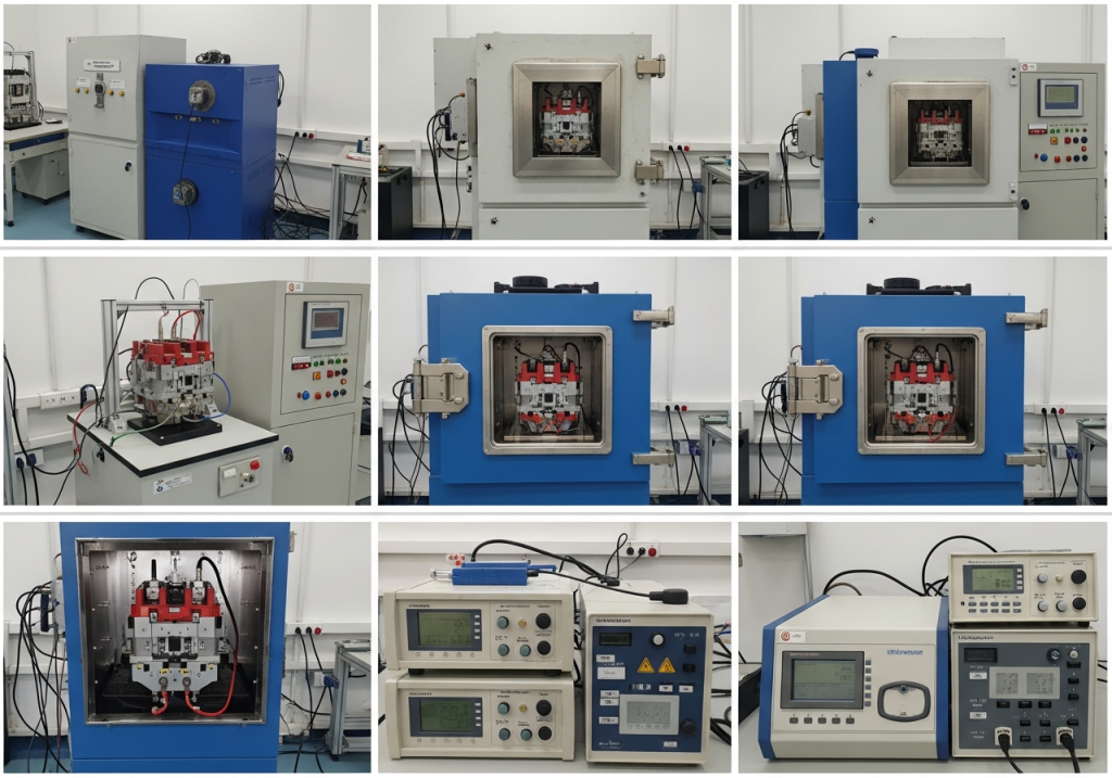
Accelerated testing in laboratories subjects contactors to elevated temperatures (to simulate continuous summer operation in hot climates) and compressed operating schedules (thousands of cycles over hours rather than weeks). These tests identify potential spring failure modes and validate that new designs achieve intended service life. Indian railways and international railway operators conduct such testing per IEC standards and internal specifications before approving contactors for revenue service, ensuring fleet reliability before deployment.
Spring Optimization for Reducing Contact Bounce and Wear
Contact bounce represents one of the most damaging phenomena in electrical contactors, particularly at high switching frequencies common in locomotive applications. When contacts close, the electromagnetic force accelerates the moving contact assembly toward the stationary contacts. The assembly possesses significant kinetic energy at impact, causing the moving contact assembly to decelerate rapidly but elastically rebound due to mechanical compliance in the system. This rebound creates momentary separation of contacts immediately after they close, lasting just 1-20 milliseconds depending on design.
During contact bounce, electrical current flowing through the partially-separated contacts creates micro-arcs that generate temperatures exceeding 5000°C at contact surfaces. These arcs cause rapid metal evaporation, ionization, and material transfer from one contact to the other. The contact surfaces deteriorate visibly as material is deposited and eroded, creating pitted surfaces and excessive surface roughness. Contact bounce is therefore one of the primary drivers of electrical life limitations in locomotive contactors—a design phenomenon that can be managed and minimized but never completely eliminated.
Spring optimization specifically targets contact bounce reduction through careful balance of multiple competing objectives. Softer springs allow easier contact closure with lower electromagnet power requirements but increase contact assembly mass and kinetic energy at impact, worsening bounce. Stiffer springs reduce kinetic energy at impact but require more powerful electromagnets, increasing coil heating and power consumption. The contact mass itself influences bounce—lighter assemblies have less kinetic energy and bounce less severely, but lightweight designs sacrifice mechanical ruggedness. Modern locomotive contactors employ electromagnetic-mechanical coupling simulation using finite element analysis to optimize these competing factors simultaneously.
One advanced technique involves multi-stage spring design where springs have different rates at different positions in the cycle. Early in the closing motion, softer springs allow rapid contact closure, minimizing contact opening duration. As contacts near closure, spring rate increases, decelerating the contact assembly and reducing impact velocity and resulting bounce. Return springs are similarly optimized to open contacts quickly enough to extinguish arcing but not so fast as to cause rebound that retards opening speed. These sophisticated designs achieve contact bounce reduction of 20-30% compared to conventional single-stage springs, extending electrical life and reducing maintenance costs.
Make/Break Characteristics and Contact Wear Mechanisms
Understanding Arcing Phenomena and Contact Erosion in High-Current Applications
When locomotive contactor contacts separate during the “break” operation, an electrical arc forms across the gap between contact surfaces. This arc represents a partially-ionized plasma channel conducting current through ionized metal vapor and gases. The arc persists as long as current magnitude exceeds the minimum current required to sustain ionization in the gap geometry. At current zero crossing (in AC applications) or when contact gap becomes sufficiently large (in DC applications), the arc extinguishes, interrupting the circuit and allowing full voltage recovery across the now-separated contacts.
The physics of arcing in high-current applications creates extraordinary conditions at contact surfaces. Contact current flowing through a few square millimeters of contact area creates current density in the range of 1,000-10,000 amperes per square millimeter. Resistance to current flow in this geometry generates resistive heating at contact spots, creating temperatures that can exceed 5000°C—well above the melting point of contact material. This extreme temperature causes metal evaporation and ionization, forming the arc plasma. The arc burns backward from the point of separation, creating visible erosion tracks on contact surfaces and preferentially eroding material from the opening (negative) contact.
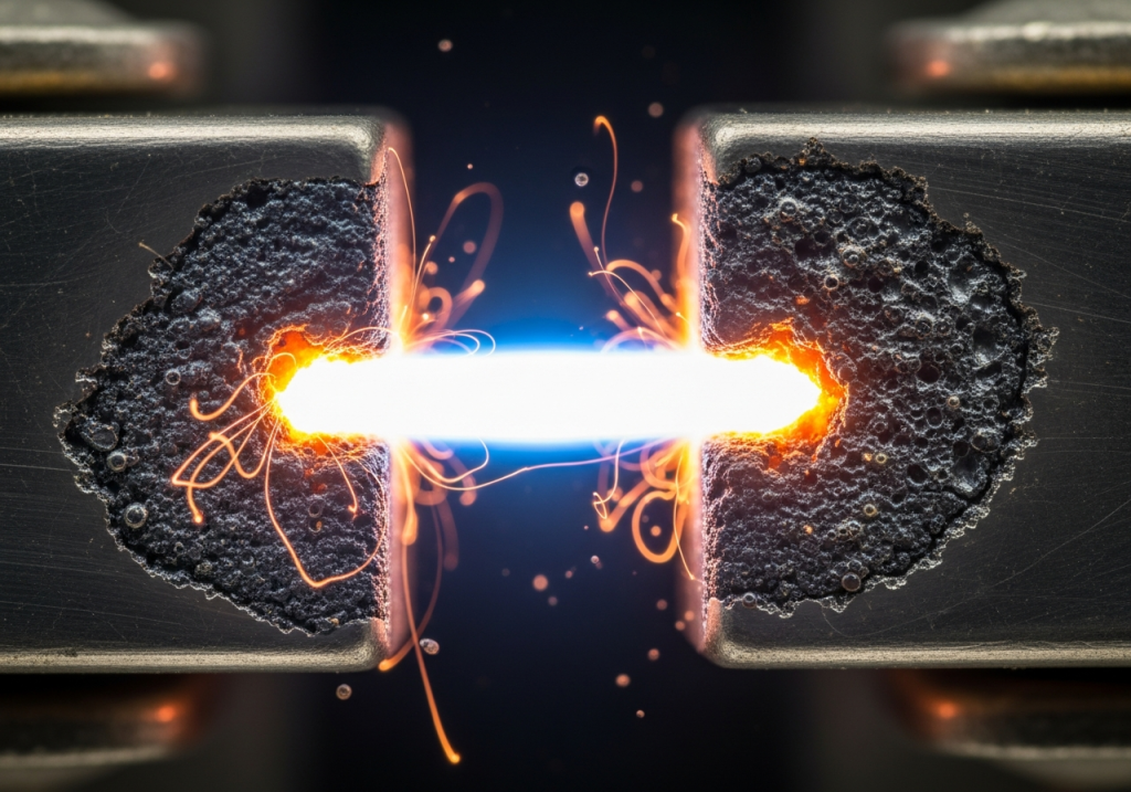
Contact erosion during arcing occurs through several mechanisms. Direct arc heating melts and vaporizes contact material at the arc root. Momentum transfer from the ionized plasma stream physically blasts material from the contact surface. Chemical reactions between vaporized contact material and atmospheric oxygen can form oxides and other compounds. In severe cases, crater formation occurs where contact material has been entirely removed from localized regions, leaving deep pits. Over thousands of arcing events, these pits accumulate and coalesce, creating rough, degraded contact surfaces with high contact resistance.
The erosion rate depends critically on current magnitude, arcing duration, contact material, and environmental factors. High current produces high temperature arcs that erode faster than low-current arcs. Long arcing duration allows more material removal per cycle. Contact material composition profoundly influences erosion resistance—silver-tin oxide contacts erode much more slowly than pure silver or silver-copper contacts due to oxide layer formation that resists sputtering. Environmental humidity and contamination can accelerate corrosion-induced contact degradation alongside direct arc erosion. Railway contactors in coastal regions experiencing salt-air corrosion often require more frequent contact replacement than identical contactors in inland locations with benign environments.
Contact Material Selection and Performance Characteristics
Selecting appropriate contact material for locomotive contactors represents a critical engineering decision balancing electrical performance, mechanical durability, cost, environmental compliance, and regulatory requirements. Historically, many railway contactors used silver-cadmium oxide contacts because cadmium oxide provides excellent arc erosion resistance and cadmium improves mechanical hardness. However, cadmium’s toxicity and environmental concerns have led to elimination of this material from new contactor designs across most railway systems.
Modern railway contactors primarily employ silver-tin oxide (AgSnO2) contacts for main power switching circuits. Silver provides exceptional electrical and thermal conductivity, essential for managing high currents and dissipating heat generated at contact surfaces. Tin oxide particles dispersed throughout the silver matrix improve arc erosion resistance by 50-100% compared to pure silver, enabling longer electrical life and extended maintenance intervals. The oxide particles resist vaporization during arcing, creating a protective surface layer that slows material erosion. Silver-tin oxide contacts maintain adequate mechanical hardness for reliable switching while resisting welding and sticking that can occur with softer pure silver contacts.
Silver-copper alloys (AgCu) represent an alternative material choice for some applications, particularly where cost constraints limit silver usage. Copper increases mechanical strength compared to pure silver, providing better resistance to contact carrier deformation and spring relaxation. However, copper’s lower thermal conductivity compared to silver results in higher contact temperatures for equivalent current-carrying conditions. Silver-copper contacts typically tolerate slightly lower current ratings than equivalent silver-tin oxide contacts, but their lower cost may be justifiable in cost-sensitive procurement decisions for non-critical contactor applications.
Silver-nickel (AgNi) contacts provide additional mechanical durability in applications expecting significant contact carrier vibration or mechanical stress. Nickel increases hardness and wear resistance, improving mechanical life in vigorous switching duty. However, nickel also slightly reduces electrical conductivity compared to pure silver, requiring somewhat larger contact area to achieve equivalent current rating. Railway operators typically reserve silver-nickel contacts for specialized applications rather than standard main power contactors.
Contact material thickness represents an important design consideration often overlooked in maintenance planning. Contacts are typically 0.5-2.0mm thick, sized to provide adequate material for erosion accommodation throughout intended service life. A contactor designed for 100,000 switching cycles with expected erosion rate of 0.01mm per 1,000 cycles would require at least 1.0mm contact thickness to provide 100,000 cycles before erosion reaches the copper base material. When contacts erode through their original thickness into the underlying copper carrier material, contact resistance increases dramatically because copper conducts current less efficiently than silver, and copper oxidizes rapidly in humid environments.
Break Speed and Arc Extinction Timing
Contact break speed—the rate at which contacts separate during the opening operation—directly determines arc duration and the resulting contact erosion. Fast-opening contacts create large air gaps quickly, accelerating arc extinction. In AC systems, successful arc extinction requires reaching sufficient gap distance and cooling before current naturally attempts to reverse direction at the next current zero crossing. If contacts open slowly, the arc burns for extended duration, accelerating contact material erosion. If contacts open too fast, mechanical stress on contact carriers and springs increases, potentially causing mechanical failure and increasing costs of contactors replacement.
Railway contactors typically achieve break speeds in the range of 0.5-2.0 meters per second depending on coil design, spring rates, and mechanical leverage. Heavier contactors handling higher currents often employ faster break speeds to minimize arcing, while lighter pilot circuit contactors sometimes use slower break speeds to reduce mechanical stress. The break speed is partially controlled by the return spring force—stronger springs accelerate contact opening, weaker springs allow slower opening. However, spring force must also provide adequate contact pressure during closed operation, creating a design tradeoff.
Arc extinction in DC systems (common in some railway applications, particularly older diesel-electric locomotives with DC generator and DC traction motor systems) requires different considerations than AC systems. DC current doesn’t naturally go through zero like AC current, so the arc persists until the contact gap becomes so large that ionization can no longer bridge the gap.
This requires larger contact gaps and/or faster opening speed in DC systems compared to AC systems. Many DC railway contactors employ arc chutes—specially shaped metal or ceramic chambers surrounding the arc zone—that cool the arc and distribute it across larger regions to promote extinction. Modern DC contactors sometimes use magnetic blowout coils that generate magnetic fields concentrating the arc and accelerating its movement and extinction.
Electrical Endurance vs Mechanical Life in Locomotive Applications
Understanding the Distinction Between Mechanical and Electrical Endurance Ratings
Railway contactors carry two distinct endurance ratings that fundamentally drive maintenance scheduling and replacement decisions. Mechanical life represents the number of opening-closing cycles the mechanical components can withstand without permanent deformation or fracture—typically 1-3 million cycles for industrial-grade contactors and up to 10 million cycles for specialized lightweight contactors. Electrical life represents the number of load-breaking cycles the contactor can perform while switching current without contact erosion exceeding acceptable limits—typically 50,000-200,000 cycles for AC-3 motor starting applications and 10,000-50,000 cycles for AC-4 plugging and jogging applications.
This distinction creates a critical insight that surprises many maintenance engineers: in 95% of real-world railway applications, electrical life determines replacement timing rather than mechanical life. A locomotive contactor rated for 1 million mechanical operations and 100,000 electrical operations at AC-3 duty reaches electrical end-of-life at 100,000 cycles, leaving 900,000 unused mechanical capacity. This represents an apparently wasteful design until one recognizes that electrical stress from arc erosion limits the contactor first, making further mechanical cycling impossible because electrical failure has already rendered the contactor unreliable.
The fundamental reason for this disparity involves the energy scales involved in mechanical versus electrical degradation. Mechanical wear from friction and abrasion removes microscopic material at rates measured in nanometers per 1,000 cycles—requiring 1-3 million cycles to accumulate sufficient material loss to cause mechanical failure. Electrical stress from arcing removes material at rates measured in micrometers per 100 cycles—a thousand times faster than mechanical wear. The arc temperatures exceed 5000°C and impart enormous energy densities at contact surfaces, causing catastrophic erosion compared to the gentler mechanical wear processes.
Mechanical Life Limitations and Spring Component Wear
Mechanical life limitations arise from multiple degradation mechanisms accumulating throughout the contactor’s operational history. Spring fatigue represents the primary mechanical life limiter in most locomotive contactors. Each compression-decompression cycle imposes stress on spring material; millions of cycles cause microscopic crack initiation and propagation that eventually leads to catastrophic failure. Modern contactor springs are engineered to operate at stress levels designed not to exceed fatigue strength, theoretically allowing infinite cycles. However, practical designs conservatively limit mechanical life to 1-3 million cycles based on field experience showing that other degradation mechanisms typically intervene before true infinite life is achieved.
Pivot bearing wear represents a secondary mechanical life limitation in contactors employing pivot connections between contact carriers and the electromagnetic coil armature. These bearings must support large forces repeated millions of times while surviving continuous locomotive vibration. Over time, bearing surfaces wear, creating increased friction and play in the mechanical linkage. Excessive play results in sluggish contact opening and closing, potentially allowing contact bounce to increase and arcing to worsen. Some advanced railway contactors employ roller bearings or plastic-on-metal bearing combinations to extend bearing life beyond mechanical component life.
Contact carrier deformation occurs when contact carrier structures yield or fatigue under repeated mechanical stress. The contact carriers experience acceleration forces during rapid contact opening and closing, and these inertial forces multiply by the mass of the contacts and mechanical components they support. Insufficient structural stiffness or material strength in contact carriers can lead to permanent deformation—bending or warping of the carrier structure that changes contact geometry and alignment. Misaligned contacts may not mate properly, resulting in increased contact resistance or partial contact area usage.
Elastic deformation of contact materials themselves represents the final mechanical life consideration. Contact materials, despite being hardened metals, still undergo elastic deformation under repeated mechanical stress. In elastic deformation, the material deforms temporarily but recovers its original shape after stress is removed. However, repeated elastic deformation can eventually transition to plastic deformation, creating permanent shape changes. The contact surface may not align properly after plastic deformation has occurred, degrading contact quality and increasing electrical resistance.
Electrical Life and IEC Utilization Categories
Electrical life depends critically on application duty category, defined in IEC 60947-4-1 standard for low-voltage electromechanical contactors and motor starters. Different categories impose different electrical stress levels, directly affecting how quickly contacts erode and electrical life is consumed. Understanding utilization categories enables proper contactor selection—using an undersized contactor for the wrong duty category causes premature electrical failure and inadequate motor protection.
AC-1 category encompasses resistive or only slightly inductive loads such as resistance heating elements and incandescent lighting. Full load current equals rated current with minimal inrush current. The power factor is high (typically above 0.95), indicating resistive rather than inductive character. Electrical life is extremely long in AC-1 applications, often approaching mechanical life limits because arcing energy per cycle is minimal. A contactor rated for 400 amperes at AC-1 duty might achieve 500,000+ electrical cycles because the low inrush current limits arcing severity. Railway applications rarely use AC-1 contactors because locomotive circuits inherently involve large inductive traction motors, not resistive loads.
AC-3 category handles squirrel-cage AC induction motors during starting and switching off while running. This category introduces significant inrush current—typically 6-7 times rated full-load current during motor starting—creating severe arcing stress. However, AC-3 duty cycles involve “make at high current” but “break at low current.” The contactor closes at high current (worst case for inrush arcing), but when opening, motor current has typically dropped near full-load running value, minimizing break arcing. This asymmetry limits electrical stress compared to fully balanced duty cycles. Electrical life in AC-3 is typically 100,000-200,000 cycles, representing a practical balance between cost and performance for most industrial and railway applications.
AC-4 category encompasses squirrel-cage motor plugging, jogging, inching, and rapid start-stop sequences. This represents the most severe duty category, requiring the contactor to make and break high currents repeatedly. Plugging involves reversing motor rotation by switching connections while the motor is still running forward, requiring the contactor to interrupt full-load current in the opposing direction. Jogging involves rapid starts and stops. These operations create intense arcing at both make and break, severely stressing contacts. AC-4 electrical life is typically only 10,000-50,000 cycles—approximately 7.5 times shorter than AC-4 despite identical mechanical operations. The difference entirely reflects increased electrical stress from making and breaking at high current repeatedly.
AC-2 category (slip-ring motor starting and switching off with slip-ring resistance in circuit during acceleration) and AC-22 category (switching highly inductive loads occasionally) represent intermediate categories with electrical life between AC-1 and AC-3. Railway contactors are almost always specified at AC-3 or AC-4 level because locomotive duty involves starting large inductive traction motors under load, creating high inrush currents characteristic of AC-3 or AC-4 service.
Real-World Service Life Prediction and Maintenance Planning
Converting electrical and mechanical cycle ratings into actual calendar service life requires understanding the specific locomotive’s operating profile. A locomotive starting its traction motors 10 times daily (typical for commuter service) would accumulate 3,650 starting cycles annually. This locomotive would consume 100,000 electrical cycles in approximately 27 years of service, suggesting 27-year intervals between contactor replacements if only electrical stress limited life. However, environmental factors, maintenance quality, and actual duty variations often compress this timeframe.
More aggressive operating profiles dramatically accelerate contactor replacement needs. A shunting locomotive performing yard switching duty might start traction motors 50+ times daily, consuming 100,000 electrical cycles in just 5-6 years. A high-frequency rapid-transit locomotive with frequent acceleration and deceleration cycles might consume electrical life even faster. Railway operators must analyze their specific fleet’s duty cycles to establish realistic replacement intervals and maintenance budgeting.
Environmental factors strongly influence actual service life independent of electrical stress calculations. Coastal railways with salt-air corrosion experience accelerated contact deterioration, often requiring 20-30% shorter intervals between contact replacement compared to inland railways in benign environments. High-temperature operations in tropical climates accelerate spring relaxation and reduce spring fatigue strength. Humid environments promote corrosion that increases contact resistance even when arc erosion hasn’t yet reached replacement limits. Dusty environments allow contamination to accumulate on contacts, interfering with electrical contact.
Predictive maintenance programs use field data to validate theoretical life predictions and guide replacement scheduling. Railway operators track contactor performance through resistance testing and visual inspection during routine maintenance. When resistance measurements begin trending upward or pitting becomes visible on contact surfaces, the contactor schedules replacement during the next planned maintenance opportunity before complete electrical failure occurs. This condition-based maintenance approach optimizes cost by replacing contactors before failure rather than on fixed calendar schedules, while maintaining reliability by preventing unexpected in-service failures.
Optimization Strategies for Railway Contactor Performance
Advanced Contact Pressure Optimization Techniques
Optimizing contact pressure for specific locomotive applications involves sophisticated analysis balancing electrical performance, mechanical durability, environmental resilience, and cost. The baseline optimization starts with calculating the minimum contact pressure required to maintain contact resistance below acceptable limits throughout the contactor’s intended service life. Contact resistance must remain sufficiently low to prevent excessive heating while carrying rated current for extended periods. Typical specifications limit contact resistance to 0.2-0.5 milliohms per contact pair, requiring pressure calculations accounting for contact material properties and expected surface contamination.
The electromagnet force available for achieving contact pressure depends on coil design, operating voltage, and duty cycle. Higher coil voltage produces stronger magnetic force, enabling higher contact pressure or larger contact gaps. However, higher voltage also increases coil power dissipation, creating heat that must be dissipated to maintain insulation integrity. Thermally stable contactors operating at maximum voltage continuously produce more waste heat but achieve superior contact pressure consistency. Duty-cycle-limited (intermittent-use) contactors can operate coils at higher effective temperature rise, enabling higher pressure with lower average heat dissipation.
Spring preload optimization involves selecting spring material, geometry, and assembly procedures to provide exactly the required spring force. Over-preload increases spring stress, accelerating fatigue and shortening mechanical life. Under-preload reduces available contact pressure as spring force weakens with age, potentially causing late-life electrical failures. Modern contactors employ quality-control procedures verifying spring force within specified tolerances during manufacturing, and maintenance procedures verify spring force periodically throughout the contactor’s service life. Springs showing significant force loss schedule replacement during the next maintenance cycle, preventing performance degradation.
Contact surface preparation and maintenance profoundly influences actual contact pressure requirements. Clean, smooth contact surfaces require less pressure to achieve low resistance than contaminated, pitted surfaces. Modern railway maintenance procedures include periodic contact cleaning using appropriate methods for each contact material—typically specialized contact cleaners for mild contamination, or mechanical burnishing with soft abrasives for heavier oxidation. This preventive cleaning maintains optimal contact resistance and allows railway operators to optimize contact pressure toward lower values, reducing spring stress and extending mechanical life.
Spring System Tuning and Load Balancing Using Advanced Simulation
Modern railway contactor optimization employs electromagnetic-mechanical coupling simulation to coordinate spring action with electromagnetic coil behavior. Finite element analysis models the magnetic field distribution within the coil and its interaction with the armature (movable part of the electromagnet). Mechanical finite element models simulate spring deformation, contact carrier motion, and contact approach. Coupling these models reveals how electromagnetic force changes as the armature moves (distance-dependent magnetic force), how spring force varies with compression, and how these forces interact to determine motion characteristics.
The simulation identifies several critical performance metrics: iron core closing time (how quickly the electromagnet snaps closed), contact closing velocity (speed at which contacts make), bounce time (duration of contact separation immediately after closing), contact break velocity (speed of contact opening), and overall cycle time (total time for complete open-close-open cycle). Each metric affects contactor performance—faster closing ensures motor starts reliably, lower bounce reduces contact erosion, faster breaking enables rapid fault interruption and arc extinction.
Multi-objective optimization adjusts spring parameters to optimize multiple competing objectives simultaneously. Lower spring constant enables faster closing (less spring force to overcome) but increases contact bounce (more kinetic energy at impact). Higher spring constant reduces bounce but requires more powerful electromagnet coils. Optimization seeks the Pareto frontier—the set of design solutions where no single parameter can be improved without degrading others. Response surface methodology creates mathematical models showing how each spring parameter influences each performance metric, allowing designers to navigate this complex design space efficiently.
Field validation confirms that simulated performance predictions match actual contactor behavior. Railway operators measure contact closing velocity, bounce duration, and break velocity on test benches and in revenue service locomotives, comparing results against simulation predictions. When predictions diverge from field measurements, engineers investigate root causes—often discovering unexpected effects like armature magnetic saturation, friction in mechanical linkages, or air resistance effects not fully captured in the simulation. These discoveries lead to refined models providing more accurate predictions for future designs.
Material Selection and Surface Treatment for Enhanced Performance
Contact material selection fundamentally influences make/break characteristics and electrical life. Silver-tin oxide contacts offer superior arc resistance compared to pure silver or silver-copper combinations, extending electrical life 20-50% depending on specific application duty category. The tin oxide particles resist vaporization during arcing, creating a protective oxide layer that slows material removal. However, silver-tin oxide contacts cost more than alternative materials, requiring economic justification through extended maintenance intervals and reduced total cost of ownership.
Contact surface treatment and finishing processes significantly impact contact performance. Contact surfaces must be extremely clean and smooth for optimal electrical performance. Manufacturing processes typically include mechanical burnishing with soft brushes or fine abrasive media to remove oxide films and establish smooth surface topology. Some manufacturers apply protective coatings to reduce oxidation during storage before installation. In-service contact cleaning (performed during routine maintenance) maintains optimal surface condition, particularly in high-humidity environments where oxidation occurs rapidly.
Contact carrier material and design also influences overall contactor performance. Aluminum or aluminum-alloy carriers provide light weight, reducing inertial forces and enabling faster contact opening and closing. However, aluminum has lower electrical conductivity than copper, potentially increasing contact resistance if current paths flow through the carrier. Copper carriers provide superior conductivity but weigh more than aluminum. Modern designs often employ hybrid structures—aluminum carriers for mechanical advantages but with copper current paths and contact attachment points for electrical optimization.
Testing, Maintenance and Reliability Considerations
Laboratory Testing Standards and Validation Procedures
Railway contactors undergo rigorous laboratory testing before approval for revenue service, ensuring that mechanical parameters and designs deliver intended performance. Indian railways (RDSO) and international railway standards require 8,000-100,000 electrical endurance test cycles depending on application category. AC-3 contactors typically undergo 50,000 cycles, while AC-4 applications require 100,000 cycles to validate contact integrity and mechanical reliability throughout electrical life. These test cycles operate at rated voltage and current, subjecting the contactor to realistic electrical stress.
Thermal cycling tests subject contactors to temperature swings from -25°C to +55°C, simulating seasonal variations in railway yards and tunnels where locomotives operate. Spring constants, electrical properties of coil insulation, and contact material properties all vary with temperature. Contactors must maintain specified performance across this temperature range without degradation. Coil insulation integrity is particularly critical—excessive heating can degrade insulation or cause complete failure. Thermal tests verify that coil temperature rise remains below specified limits (typically 60-80 kilowatts rise at rated continuous current).
Megger insulation testing with 500V direct current confirms electrical safety of coil winding insulation. Resistance should remain above 1 megohm (1,000,000 ohms) throughout the contactor’s service life. Contact resistance measurements with precision microohm meters verify that contact quality remains within specification—typically 0.0-0.4 milliohms for main power contacts and 0.0-2.0 milliohms for pilot circuit contacts. Visual inspection of contact surfaces with optical magnification identifies pitting, erosion, and surface degradation requiring contact replacement.
Short-circuit withstand testing verifies that contactors can handle momentary fault currents without mechanical failure. During fault conditions, extremely high currents flow through contacts momentarily before protection devices (circuit breakers, fuses) interrupt the circuit. The electromagnetic force at high fault current can exceed 100 kilograms-force on contact carriers, requiring robust mechanical design to prevent armature or carrier deformation. Contactors undergo proof testing at 1.5-2.0 times rated current for duration of 1-3 seconds, verifying mechanical integrity without actual fault conditions.
Field Inspection and Condition Monitoring Programs
Railway maintenance technicians perform visual inspections of contactor contacts through observation ports or by removing protective covers. Contact surfaces should appear smooth and silvery in new or well-maintained contactors. Pitting (small surface cratering), oxidation (dark or discolored surfaces), or material transfer (rough buildup of material) indicates contact degradation requiring attention. Severely pitted or eroded contacts indicate accumulated electrical stress approaching or exceeding replacement limits.
Resistance measurements using precision microohm meters (accurate to ±0.01 milliohms) provide quantitative assessment of contact quality. Normally open contacts in the open position should show essentially infinite resistance (megohms), confirming proper contact separation. When manually depressed or with coil energized to close contacts, resistance should drop to specification range (typically 0.1-0.4 milliohms depending on current rating). Elevated resistance (0.5-2.0 milliohms) indicates contact degradation but not yet requiring immediate replacement. Extremely high resistance (10+ milliohms) demands urgent replacement, as such high resistance causes dangerous overheating.
Coil resistance testing using precision multimeters detects wire insulation damage, partial internal shorts, and complete open-circuit failures. Measured coil resistance should match manufacturer specification (typically 50-500 ohms depending on contactor size and design). Resistance significantly higher than specification suggests partial open-circuit or very fine wire breakage. Resistance significantly lower than specification suggests short-circuited turns or damaged insulation bridging across windings. Either condition requires coil replacement.
Spring compression force testing using calibrated force gauges determines whether springs have weakened. Pressing contacts to full closure should require force closely matching specification—typically 30-60 kilograms-force. Springs that require significantly less force suggest mechanical loosening or spring degradation. Mechanical loosening sometimes allows spring tightening. True spring weakness requires spring replacement, as weakened springs cannot maintain adequate contact pressure.
Preventive Maintenance and Optimal Replacement Strategies
Preventive maintenance scheduling balances cost against reliability. Railway operators establish inspection intervals based on operating hours, calendar time (months or years), and duty category. Typical inspection intervals range from 500 operating hours (intensive duty locomotives) to 2,000 operating hours (light-duty locomotives) between full inspections. Calendar intervals typically range from 6 months to 2 years depending on climate and operating environment. Contact replacement intervals typically approach electrical life estimates—100,000-150,000 electrical cycles—combined with condition monitoring to identify contactors requiring early replacement due to environmental factors or unusual duty.
Complete contactor replacement is often more cost-effective than individual component replacement when multiple degradation mechanisms are present. A contactor with degraded contacts, weak springs, and corroded coil terminals might cost 60% as much to repair through component replacement as purchasing a new contactor. Complete replacement ensures all components are in factory-new condition, eliminating risks of residual problems. Repair typically reserves for minor issues like corroded terminal contacts or loose mechanical bolts rather than major component replacement.
Inventory management requires maintaining replacement contactors on hand for rapid deployment during unexpected failures. Most major railway operators maintain 10-20% of fleet size in replacement contactors (depending on fleet diversity), ensuring spare capacity for replacing failed units. Some contactors repair shops maintain cores (used contactors returned for refurbishment) that can be rebuilt and restored to like-new condition more cost-effectively than purchasing new contactors. Refurbished contactors typically cost 40-60% of new contactor prices after cleaning, bearing restoration, spring replacement, contact resurfacing, and electrical testing.
Advanced condition monitoring using vibration sensors and acoustic monitoring can detect early signs of contactor problems before contact resistance measurements reveal degradation. Vibration signatures change as springs weaken or contacts become misaligned. Acoustic signatures of arcing change as contact surfaces deteriorate. These early-warning technologies enable prediction of remaining useful life more accurately than calendar-based replacement intervals, potentially extending contactor service life or identifying problems requiring intervention before catastrophic failure.
Future Considerations
Railway contactors represent critical components determining locomotive reliability, operational efficiency, and safety. The mechanical parameters governing contact normal load and spring design profoundly influence both electrical endurance and mechanical reliability. Optimization of these parameters requires balancing multiple competing objectives—maximizing contact pressure for electrical performance while minimizing pressure to extend spring life, achieving fast contact closing for reliable motor starts while minimizing kinetic energy and bounce, and opening contacts quickly to extinction arcs while minimizing mechanical stress.
Modern railway contactors incorporate sophisticated electromagnetic-mechanical coupling optimization, advanced contact materials, and systematic maintenance programs that extend service life and improve reliability compared to earlier designs. Laboratory testing validates performance predictions before deployment, and field maintenance programs monitor actual contactor condition throughout service life. Railway operators who understand the underlying physics of contactor operation, select appropriate duty ratings for specific applications, and implement systematic maintenance programs achieve fleet performance and cost-effectiveness superior to those relying on reactive failure replacement.
Looking forward, emerging technologies promise further improvements in locomotive contactor performance. Solid-state switching devices (semiconductor switches) may eventually supplement or replace electro-mechanical contactors for some applications, offering faster switching speeds and eliminating mechanical wear. However, electro-mechanical contactors will likely remain essential for high-current traction circuits where power semiconductor losses become prohibitive. Advanced diagnostic techniques including condition monitoring and predictive algorithms will enable increasingly accurate prediction of remaining useful life, optimizing maintenance scheduling and reducing unexpected failures. Continued evolution of contact materials, spring designs, and electromagnetic optimization will extend both electrical and mechanical life, further improving locomotive reliability and reducing total cost of ownership for railway operators worldwide.
Frequently Asked Questions (FAQ)
How do I determine if a railway contactor needs replacement based on contact wear?
Monitor contact surface condition through visual inspection for pitting and erosion. Measure contact resistance—resistance above 0.5 ohms indicates excessive wear. Compare actual contact thickness against manufacturer specifications; if erosion exceeds limits (typically >0.060″ per contact pair), replacement is required. Most railway operators replace contactors after reaching 100,000-150,000 electrical switching cycles or when resistance measurements exceed acceptable thresholds, whichever occurs first.
Why do locomotive contactors fail despite meeting mechanical life ratings?
Locomotive contactors fail primarily due to electrical stress (arc erosion) rather than mechanical wear. Most railway contactors reach electrical end-of-life at 50,000-200,000 cycles, while mechanical components remain serviceable after 1-3 million cycles. Harsh railway environments accelerate failure through moisture ingress causing corrosion, vibration causing contact misalignment, and dust contamination increasing resistance. Additionally, improper utilization category selection—using AC-3 rated contactors for AC-4 jogging duty—dramatically reduces electrical life to 10,000-20,000 cycles.
What spring design improvements reduce contact bounce and extend contactor life?
Modern contactors optimize spring design through electromagnetic-mechanical coupling simulation to achieve bounce times under 5 milliseconds. Key improvements include precise spring constant selection to balance closing velocity against rebound energy, optimized contact mass to minimize inertial effects, and multi-stage spring systems that control motion at different phases. Higher contact force (within material strength limits) helps overcome elastic deformation causing bounce. Advanced designs integrate reaction springs that work synergistically with contact springs to absorb and dissipate bounce energy, improving contact life 20-30% compared to conventional designs.