
When you’re designing AC contactors for electric locomotives, you can’t compromise—failure means lost traction, compromised braking, and cascading faults across critical systems. You need purpose-engineered designs that meet EN 50155, IEC 60077-2, and IEC 61373, built to handle -40°C to +70°C thermal cycling, vibration spanning 10–2000 Hz, and corrosive contaminants. Contact materials, arc quenching geometry, and sealing architecture must be validated from the earliest engineering phase. Keep going to understand exactly how it’s done.
What are the critical design parameters for AC contactors in electric locomotives to ensure reliability under vibration and extreme environmental conditions?
AC contactors in electric locomotives face an exceptionally demanding operational environment, characterized by relentless mechanical vibrations, ranging from 10 to 2000 Hz, and severe thermal cycling between -40°C and +70°C, alongside high humidity, dust, and salt fog exposure. These conditions accelerate degradation mechanisms such as contact wear, electrical erosion, and mechanical fatigue, directly impacting the overall reliability and safety of the power control systems. The design of these critical components must therefore integrate specialized features to ensure resilience and longevity.
Key design parameters focus on enhancing the electromechanical robustness and contact integrity. This includes implementing high-inertia armature damping and reinforced pole-face geometries to absorb mechanical shocks and prevent vibration-induced contact bounce, which can lead to rapid wear and welding of contacts. Additionally, anti-chatter latching mechanisms are crucial for maintaining stable contact closure, especially during dynamic loading conditions inherent to locomotive operation. Material selection for contacts, such as silver-tin oxide or silver-nickel alloys, is vital for resisting arc erosion and maintaining low contact resistance over millions of operations.
Environmental hardening is another indispensable aspect of AC contactor design for rail applications. This involves employing IP67-rated housings to prevent ingress of dust and moisture, silicone-gasketed enclosures for enhanced sealing, and conformal-coated printed circuit boards for auxiliary control coils to protect against corrosion and electrical short circuits. Corrosion-resistant stainless-steel fasteners and mounting brackets further contribute to the long-term structural integrity in harsh railway environments. Adherence to standards like IEC 60077-2 for railway rolling stock and rigorous MIL-STD-810H compliant vibration testing confirms the ability of these components to withstand the extreme operational stresses.
Key Takeaways
- Railway-certified AC contactors must comply with EN 50155 and IEC 60077-2, governing dielectric strength, mechanical endurance, and traction-specific load conditions.
- Locomotive contactors face continuous vibration across 10–2000 Hz, requiring IEC 61373-compliant designs validated against coupling shock impulse forces.
- Contact bounce and chatter re-ignite arcs after each rebound, accelerating erosion and significantly shortening contactor service life.
- Optimized armature mass, calibrated contact pressure springs, and reinforced pole-face geometry collectively suppress bounce and chatter under railway vibration loads.
- Contactor failure risks welded contacts, coil failure, traction power loss, and uncontrolled regenerative braking failure, potentially stranding a consist entirely.
The Indispensable Role of AC Contactors in Electric Locomotives
When you examine the power architecture of an electric locomotive, you’ll find AC contactors at the heart of every critical switching operation — from controlling traction motor circuits to managing auxiliary power distribution. These components directly determine operational safety and system efficiency, as a single contactor failure can interrupt traction power, trigger emergency shutdowns, or compromise braking systems at speed. Unlike standard industrial contactors designed for stable, controlled environments, locomotive contactors must perform these same functions while enduring mechanical shock, continuous vibration, extreme temperatures, and aggressive contaminants that industrial equipment will never encounter.
Core Functionality in Traction Systems:
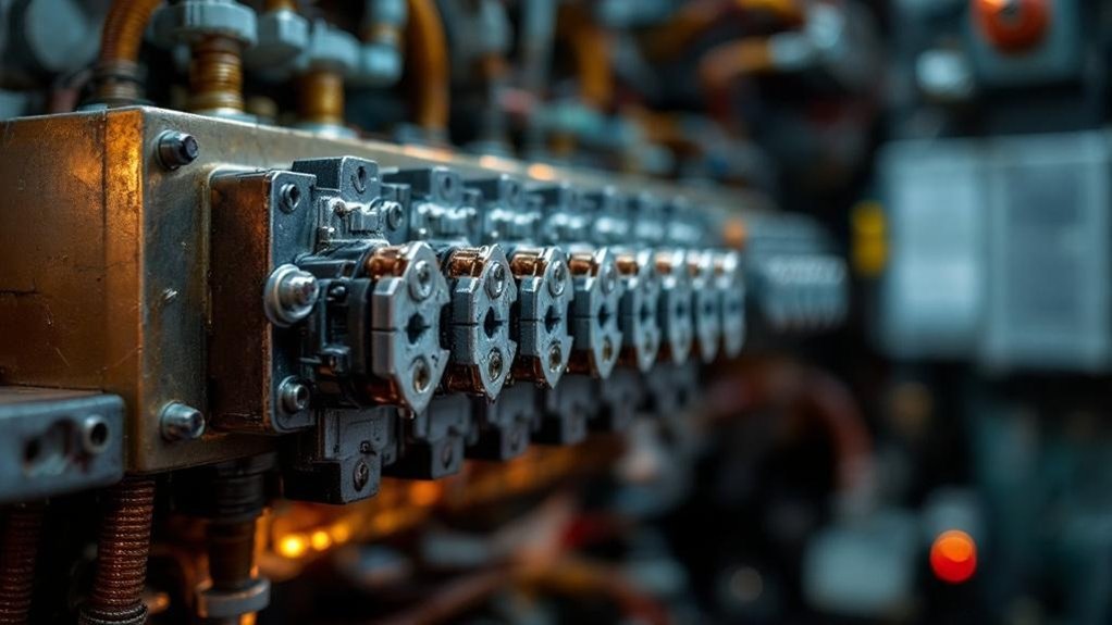
As the primary switching elements in an electric locomotive’s power circuit, AC contactors govern the flow of high-voltage, high-current energy to traction motors and auxiliary systems with precision and reliability that no other component can replicate. Electric locomotive contactors manage circuits operating at voltages exceeding 25kV in some configurations, executing thousands of switching cycles under full load conditions across a locomotive’s service life.
You’ll find these devices controlling traction motor engagement, regenerative braking handovers, and auxiliary power distribution simultaneously. Unlike industrial counterparts, railway vibration resistance isn’t a secondary consideration—it’s a foundational design requirement. Each switching operation must occur with consistent contact force and arc suppression performance, regardless of track-induced mechanical stress, ensuring operational safety and preventing cascading failures within the locomotive’s integrated power management architecture.
Impact on Operational Safety and Efficiency:
The precision switching that AC contactors deliver in traction circuits directly determines whether an electric locomotive stays operational or fails mid-route. When a contactor fails, you’re not just losing one switching component—you’re risking full traction power loss, uncontrolled regenerative braking failure, and cascading faults across auxiliary systems. These aren’t theoretical risks; they’re operational realities that railway engineers actively design against.
AC contactor reliability directly governs locomotive uptime, passenger safety, and schedule adherence. A single welded contact or coil failure can strand a consist, disrupt network-wide scheduling, and trigger emergency protocols. Achieving extreme environmental performance means engineering contactors that eliminate these failure modes under simultaneous electrical, thermal, and mechanical stress. Every design decision—from arc chamber geometry to contact gap tolerances—must prioritize uninterrupted switching performance throughout the locomotive’s operational service life.
Comparison with Industrial Applications:
Although AC contactors serve as fundamental switching components across countless industrial environments, their deployment within electric locomotive power systems imposes operational demands that standard industrial designs simply cannot satisfy. Industrial contactors typically operate within controlled facilities where vibration, thermal cycling, and contamination exposure remain moderate and predictable.
Locomotive environments, by contrast, subject contactors to continuous mechanical shock, multi-axis vibration profiles, extreme temperature differentials, and aggressive chemical contamination simultaneously. You’ll find that industrial-grade contactors carry ratings validated through benign laboratory conditions, whereas railway-certified contactors must demonstrate compliance with EN 50155 and IEC 61373 standards, confirming verified performance across genuinely hostile conditions. This fundamental distinction in operational severity means that AC contactor reliability in locomotive applications demands purpose-engineered solutions rather than adapted industrial equivalents.
The Harsh Reality: Environmental Stresses in Rail

When you design or specify AC contactors for electric locomotive applications, you must confront environmental stresses that far exceed those encountered in stationary industrial installations. Your contactor must simultaneously withstand continuous mechanical vibration and shock loads from track irregularities, extreme thermal cycling driven by traction power demands and ambient fluctuations, and persistent exposure to humidity, airborne particulates, and corrosive atmospheric contaminants. Understanding each of these stress categories in detail is essential to achieving the AC contactor reliability that locomotive service demands.
Mechanical Vibration and Shock Resilience:
Electric locomotives operate within one of the most mechanically aggressive vibration environments imaginable, exposing every onboard component—including AC contactors—to continuous broad-spectrum vibrations spanning 10 to 2000 Hz. Track irregularities, wheel-rail interactions, and coupling forces compound these stresses, triggering contact bounce and accelerating mechanical fatigue.
Robust AC contactor reliability demands engineering solutions targeting three critical failure mechanisms:
- Contact bounce suppression — reinforced spring assemblies and optimized contact pressure prevent unintended circuit interruptions during high-frequency excitation.
- Structural fatigue resistance — rigid mounting configurations and vibration-damping hardware counteract resonance-induced stress fractures in housings and terminals.
- Shock load absorption — EN 61373-compliant designs validate contactor integrity against sudden impulse forces exceeding operational thresholds during coupling events.
Ignoring these factors directly compromises your locomotive’s operational continuity.
Extreme Thermal Cycling and Management:
Mechanical punishment from vibration and shock is only part of the story—your AC contactors must simultaneously endure thermal extremes that would render lesser components unreliable within months. Electric locomotive operating environments expose contactors to ambient temperatures swinging from -40°C to +70°C, sometimes within remarkably short timeframes as locomotives enter different climate zones or get into tunnels.
These rapid fluctuations don’t merely stress components—they actively degrade them. Insulation materials lose dielectric strength under repeated thermal cycling. Metallic components expand and contract at differing rates, inducing mechanical fatigue at joints and contact interfaces. Coil resistance shifts with temperature, directly affecting pickup and dropout voltages.
Effective thermal management demands careful material pairing with matched expansion coefficients, high-temperature-rated insulation systems, and coil designs that maintain reliable actuation across the entire specified temperature envelope.
Humidity, Dust, and Corrosive Atmospheres:
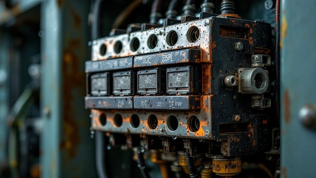
Beyond thermal and mechanical stresses, your AC contactor reliability faces an equally punishing threat from the locomotive’s atmospheric environment. Operating across coastal routes, tunnels, and industrial corridors exposes contactors to conditions that systematically degrade electrical performance.
Three primary atmospheric threats demand deliberate engineering countermeasures:
- High Humidity (>95% RH): Persistent moisture penetrates enclosures, promotes electrochemical corrosion across contact surfaces, and creates conductive films that trigger unintended current paths and short circuits.
- Particulate Contamination: Airborne carbon dust, metal particles, and ballast debris accumulate on contact assemblies, accelerating wear and compromising insulation resistance.
- Salt Fog and Chemical Exposure: Coastal and industrial environments introduce corrosive chlorides and industrial pollutants that rapidly oxidize contact materials, increasing contact resistance and causing premature failure.
Engineering for Durability: Electromechanical Design
When you engineer AC contactors for electric locomotive service, you must prioritize electromechanical design features that directly counter the destructive forces railway environments impose. Two critical focus areas are mitigating contact bounce and chatter, and optimizing contact pressure with sufficient over-travel to maintain circuit integrity under sustained vibration and shock loading. Getting these parameters right separates a contactor that achieves its rated operational life from one that fails prematurely under the mechanical punishment of rail service.
Mitigating Contact Bounce and Chatter:
Contact bounce and chatter rank among the most insidious threats to AC contactor reliability in electric locomotive applications, because each uncontrolled rebound of the contact bridge re-ignites the arc, accelerating erosion and shortening service life. Engineers counter this through three targeted design strategies:
- Optimized armature mass — Reducing moving mass lowers kinetic energy at impact, minimizing post-closure rebound amplitude.
- Calibrated spring characteristics — Precisely tuned contact pressure springs maintain consistent closing force, suppressing secondary bounces under railway vibration loads.
- Reinforced pole-face geometry with anti-chatter latching mechanisms — These magnetic system designs ensure rapid, decisive flux buildup, driving the armature to its seated position without oscillation.
You’ll find that combining all three strategies delivers measurably superior Railway Vibration Resistance and extends your locomotive contactor’s operational lifespan.
Optimized Contact Pressure and Over-travel:
Eliminating contact bounce and chatter gets you halfway to a reliable contactor — but the mechanical precision you’ve built into your armature and spring system only delivers its full value when the contacts themselves close with sufficient force and travel. Two parameters govern this directly: contact pressure and over-travel.
| Parameter | Minimum Specification |
|---|---|
| Contact Pressure | ≥3.5 N |
| Over-travel | ≥0.8 mm |
| Overheating Risk (below spec) | Meaningfully elevated |
| Electrical Life Impact | Reduced under low pressure |
| Railway Vibration Tolerance | Maintained at spec values |
Maintaining ≥3.5 N contact pressure ensures stable electrical connection under locomotive vibration loads. Over-travel of ≥0.8 mm compensates for contact wear, preserving consistent closure force throughout the contactor’s operational life.
Advanced Contact System Engineering

When you engineer AC contactors for electric locomotive service, you must treat the contact system as the most failure-critical assembly in the entire switching mechanism. You’ll need to specify contact materials engineered for arc resistance, design arc quenching geometries that interrupt high-inductive railway loads within milliseconds, and implement degradation monitoring strategies that predict contact wear before it reaches a failure threshold. Each of these engineering disciplines directly determines AC contactor reliability across the hundreds of thousands of switching cycles a locomotive accumulates in service.
Specialized Contact Materials for Arc Resistance:
At the heart of any high-performing AC contactor lies the contact material itself—and in electric locomotive applications, that material selection is non-negotiable. When you’re switching high currents under relentless mechanical stress, the wrong material accelerates failure rapidly.
Engineers prioritize two proven alloys:
- Silver-Tin Oxide (AgSnO₂) — delivers exceptional arc erosion resistance and prevents contact welding under repeated high-current interruptions, maintaining stable contact resistance across thousands of switching cycles.
- Silver-Nickel (AgNi) — offers superior mechanical hardness and thermal stability, critical when locomotive contactors endure continuous vibration alongside high-temperature operation.
- Low Contact Resistance Properties — both materials minimize resistive heating at the contact interface, directly protecting upstream locomotive power circuits from thermal degradation.
Choosing correctly between these materials defines your contactor’s operational lifespan under railway conditions.
Efficient Arc Quenching and Interruption:
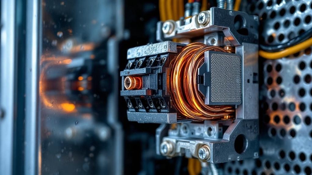
Selecting the right contact material addresses only half the reliability equation—how your contactor *extinguishes* the arc during contact separation determines whether those materials survive long-term. Arc-quenching chambers in locomotive-grade AC contactors use segmented metal arc splitters to divide and rapidly cool the arc column, forcing extinction within milliseconds. Engineers orient these splitter plates perpendicular to the arc’s path, increasing its length and dissipating energy across multiple gaps simultaneously.
Magnetic blowout coils generate directional electromagnetic fields that drive the arc into the quenching chamber, accelerating extinction. Ceramic side walls withstand repeated high-temperature arc exposure without degradation. This coordinated architecture—geometry, magnetics, and materials working together—directly reduces contact erosion per switching cycle, extending your contactor’s operational lifespan under the continuous high-frequency switching demands of electric locomotive power management systems.
Degradation Monitoring and Life Prediction:
Integrating real-time degradation monitoring transforms how you manage AC contactor reliability across a locomotive fleet’s operational lifecycle. Embedded sensors continuously track critical parameters, enabling predictive maintenance before failures disrupt operations.
Key monitoring methodologies include:
- Contact voltage drop analysis — Rising millivolt readings across closed contacts indicate progressive surface erosion, oxidation, or contamination requiring intervention.
- Current waveform diagnostics — Deviations in switching transients reveal mechanical timing drift, coil deterioration, or contact bounce patterns correlating with reduced operational lifespan.
- Thermal profiling — Continuous temperature monitoring at contact interfaces identifies abnormal resistance increases, flagging imminent failure before thermal runaway occurs.
Analytical algorithms process this multi-parameter data against established degradation models, calculating remaining useful life with measurable confidence intervals. You’re consequently replacing components based on actual condition rather than fixed maintenance schedules, optimizing both Railway Vibration Resistance performance and fleet availability.
Environmental Hardening and Protection
When you engineer AC contactors for electric locomotive environments, you must treat environmental hardening not as an afterthought but as a foundational design discipline that directly governs AC contactor reliability across the unit’s service life. Your enclosure design must achieve robust IP-rated sealing to block moisture ingress, airborne particulates, and conductive contaminants that rail operating environments continuously generate. You’ll also need to integrate corrosion-resistant materials, specialized coatings, and rigorous EMC shielding strategies to ensure the contactor performs without degradation despite relentless exposure to traction-induced electrical noise, chemical pollutants, and the demanding mechanical stresses inherent to railway vibration resistance requirements.
Enclosure Design for Environmental Sealing:
Against the relentless ingress of dust, moisture, and corrosive contaminants that characterize active locomotive service environments, IP67-rated housings and silicone-gasketed enclosures form the primary defensive architecture for AC contactor reliability. These engineered barriers maintain internal component integrity under sustained operational stress.
Your enclosure design strategy must address three critical protection layers:
- Dust exclusion — IP67 certification guarantees complete particulate ingress prevention, protecting sensitive contact assemblies from conductive debris accumulation.
- Moisture sealing — Silicone gaskets maintain compression integrity across thermal cycling extremes, preventing condensation infiltration that accelerates insulation degradation.
- Chemical resistance — Enclosure materials resist locomotive-specific corrosives, including brake particulates, lubricant vapors, and tunnel-atmospheric contaminants.
Together, these measures directly extend service intervals, reduce unscheduled maintenance events, and sustain consistent AC contactor switching performance throughout the locomotive’s operational lifecycle.
Corrosion-Resistant Materials and Coatings:
Corrosion doesn’t announce itself—it compounds silently across fasteners, brackets, and circuit assemblies until component failure forces an unscheduled maintenance event. In locomotive environments, you’re dealing with salt spray, condensation cycling, and industrial chemical exposure that accelerate electrochemical degradation on every exposed surface. Specifying stainless steel fasteners and mounting brackets eliminates galvanic vulnerability at mechanical attachment points, where corrosion typically initiates first.
For printed circuit boards governing contactor control logic, conformal coatings provide a critical dielectric barrier against moisture ingress, conductive contamination, and fungal growth. You should select coating materials—acrylic, polyurethane, or silicone—based on the specific thermal and chemical profile of the locomotive’s installation zone. Together, these material choices extend contactor service intervals and directly support AC contactor reliability across the locomotive’s operational lifespan.
Electromagnetic Compatibility (EMC) Considerations:
Material hardening stops at the surface—what your locomotive’s control architecture faces from within is an electromagnetic environment that can corrode signal integrity, trigger false switching events, and destabilize traction control systems just as effectively as physical corrosion degrades hardware.
Designing AC contactors for EMC compliance in electric locomotive environments requires deliberate engineering at multiple levels:
- Shielded coil assemblies suppress conducted emissions generated during switching transients, protecting adjacent signaling and safety electronics.
- Integrated RC snubber circuits attenuate voltage surges across contact gaps, reducing radiated interference within traction control enclosures.
- Compliance with EN 50121-3-2 ensures your contactor meets railway-specific EMC emission and immunity thresholds, validating performance under realistic locomotive operational spectra.
Without these measures, your contactor becomes an active interference source—undermining the very electronic systems it’s designed to serve.
Compliance and Validation: Standards and Testing
When you engineer AC contactors for electric locomotive service, you must validate every design decision against a rigorous framework of railway-specific standards, including IEC 60077-2 and EN 50155, which define performance thresholds for traction electrical equipment under real-world rail conditions. You’ll subject prototype units to MIL-STD-810H-compliant vibration and shock test profiles that replicate the mechanical punishment locomotives endure across diverse track conditions and speeds. Beyond initial qualification, you must run accelerated life testing protocols that compress years of operational stress into controlled laboratory cycles, giving you quantifiable reliability data and confirming that your contactor design will meet its rated service life without unexpected failure.
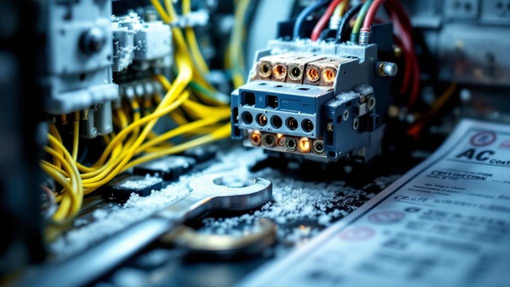
Adherence to Railway-Specific Standards (e.g., IEC 60077-2, EN 50155):
Designing AC contactors for electric locomotives without referencing established railway standards is an exercise in guesswork. Two frameworks define what’s acceptable in locomotive contactor design:
- IEC 60077-2 governs electrical equipment for railway rolling stock, specifying performance thresholds for switching devices under traction-specific load conditions, dielectric strength, and mechanical endurance.
- EN 50155 addresses electronic equipment on rolling stock, mandating compliance across temperature cycling, vibration profiles, humidity exposure, and electromagnetic compatibility—conditions your contactor will face daily.
- Type testing and validation protocols under these standards require documented proof of AC contactor reliability through repeatable, witnessed laboratory procedures—not manufacturer claims alone.
You can’t retrofit compliance after design. Both standards must drive material selection, arc quenching geometry, and enclosure ratings from the earliest engineering phase.
MIL-STD-810H Compliant Vibration and Shock Testing:
Though IEC 60077-2 and EN 50155 establish the baseline for railway contactor compliance, MIL-STD-810H fills a critical gap by providing the most rigorous, methodologically defined vibration and shock test protocols available for validating mechanical integrity under extreme operational stress. Method 514.8, Category 24 specifically targets ground vehicle and rail-applicable platforms, subjecting AC contactors to sustained broadband random vibration profiles and high-amplitude shock pulses that replicate real locomotive operating conditions.
You’re validating contact bounce resistance, coil retention integrity, and structural chassis durability simultaneously across defined frequency sweeps and g-force thresholds. These tests expose failure modes that standard railway certifications don’t fully capture—particularly fatigue-induced contact misalignment and mounting bracket fracture. MIL-STD-810H compliance accordingly doesn’t replace railway standards; it strengthens your validation architecture by closing critical mechanical stress verification gaps.
Accelerated Life Testing and Reliability Assessment:
Accelerated life testing bridges the gap between laboratory validation and decades of real-world locomotive service by compressing years of operational stress into controlled, measurable test cycles. You validate AC contactor reliability by subjecting components to simultaneous thermal shock cycling and rated electrical loads, exposing failure modes that standard qualification testing misses.
Three critical assessment parameters define a rigorous accelerated life test protocol:
- Operational endurance threshold: Contactors must complete over 1,000,000 switching operations under full rated current without contact degradation or mechanical failure.
- Thermal shock cycling: Sequential exposure to extreme temperature differentials simulates decades of locomotive service within compressed timeframes.
- Load-concurrent stress application: Electrical and mechanical stresses apply simultaneously, replicating actual locomotive operating conditions rather than isolated laboratory variables.
This methodology generates statistically defensible lifespan predictions that support maintenance scheduling and fleet reliability management.
Frequently Asked Questions
What Distinguishes AC Contactors Used in Locomotives From Those in General Industrial Applications?
You’ll find that locomotive AC contactors push far beyond what industrial-grade units can handle. They’re engineered to withstand railway-specific vibration profiles per IEC 61373, extreme temperature swings, high-altitude pressure drops, and aggressive chemical exposure. You’re also dealing with higher short-circuit ratings, enhanced arc quenching for traction-load switching, and IP67-rated enclosures—specifications that standard industrial contactors simply aren’t designed or certified to meet.
How Do AC Contactors Contribute to the Overall Energy Efficiency of Electric Locomotives?
When you deploy high-efficiency AC contactors in electric locomotives, you directly reduce resistive losses during switching transfers. Contactors with low-resistance silver-alloy contacts minimize voltage drops across high-current circuits, preserving traction motor power delivery. Fast, precise switching reduces arc duration, cutting energy dissipation. You also enable optimized regenerative braking sequences, recovering kinetic energy back into the supply network—maximizing overall locomotive energy efficiency across demanding operational duty cycles.
What Are the Immediate Consequences of an AC Contactor Failure in an Electric Locomotive?
Like a broken link in a chain, a failed AC contactor immediately disrupts your locomotive’s traction power circuit, triggering emergency shutdowns per IEC 60077 protection protocols. You’ll experience total propulsion loss, compromised auxiliary system performance, and potential arc flash hazards. Your onboard diagnostics flag critical fault codes, forcing unscheduled service interruptions that cascade into delayed consists, revenue loss, and mandatory compliance inspections before returning the locomotive to operational status.
How Frequently Should AC Contactors in Electric Locomotives Undergo Scheduled Maintenance Inspections?
You should inspect AC contactors in electric locomotives every 30,000–50,000 operational kilometers or every six months, whichever comes first. Follow IEC 60077 and manufacturer-specified maintenance intervals closely. During each inspection, you must assess contact wear depth, spring tension, arc chute integrity, and coil resistance. High-duty-cycle routes demand shorter intervals, so you’ll need to adjust schedules based on actual switching frequency logs and thermal stress data.
Can Damaged Locomotive AC Contactors Be Field-Repaired, or Do They Require Complete Replacement?
The answer depends on the damage type—but most failures demand full replacement. You can’t risk recalibrating worn contact assemblies or compromised arc chutes mid-route. Field repairs on locomotive AC contactors violate IEC 60077 compliance, introduce unverified tolerances, and invite catastrophic switching failures under traction loads. If you’ve identified contact erosion, coil degradation, or mechanical wear, replace the unit completely using OEM-certified components to maintain AC Contactor Reliability.