What is the expected lifespan of a Grid Box in an EMD locomotive, and what factors affect it? The short answer: 8-15 years in typical freight service, often aligning with a 20-30 year locomotive service life through rebuild cycles. Lifespan varies with duty cycle, thermal stress, traction motor loading, braking frequency, ambient dust, electrical systems health, and maintenance quality. Below are fast steps to extend life and lower maintenance costs in rail operation.
Keep resistive grids clean to prevent hot spots and arcing. Verify blower airflow to manage energy consumed as heat. Monitor traction motor current during dynamic brake events. Align rebuild intervals with prime mover overhaul windows. Inspect electrical systems for loose lugs and insulation wear. Log braking profiles on freight trains and passenger service. Use IR thermography after heavy freight service runs. Test contactors and grid fans before peak seasons. Replace corroded bus bars to maintain reliability. Standardize procedures across rail operators for cost-effective upkeep.
| Action | Purpose/Focus |
|---|---|
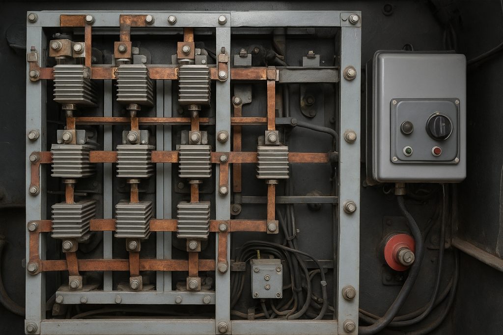
| Keep resistive grids clean | Prevent hot spots and arcing |
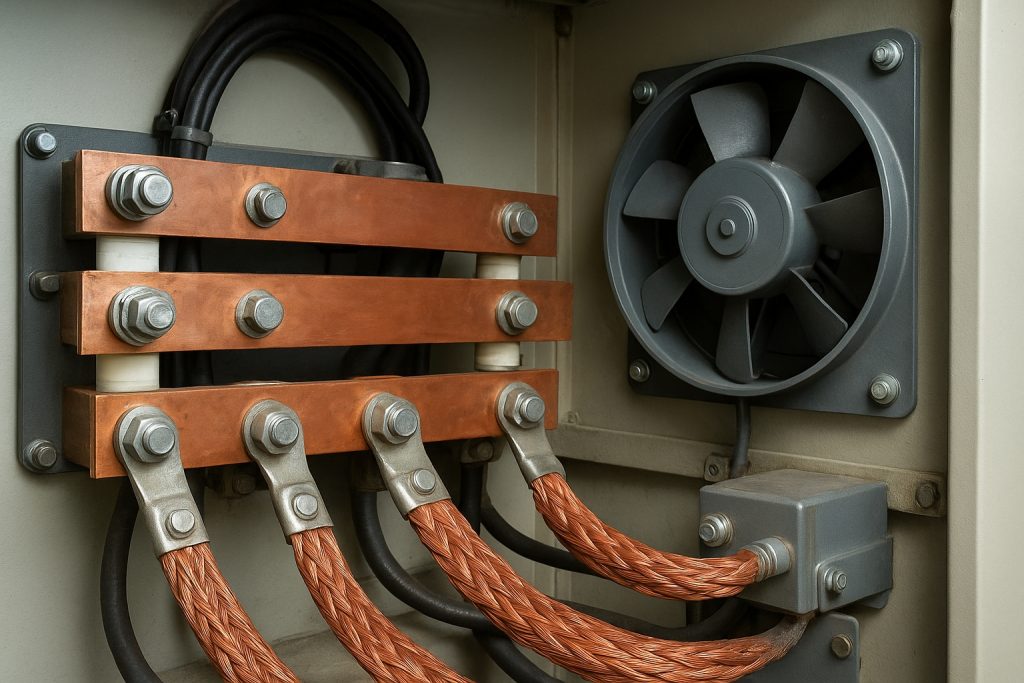
| Verify blower airflow | Manage energy consumed as heat |
| Monitor traction motor current | During dynamic brake events |
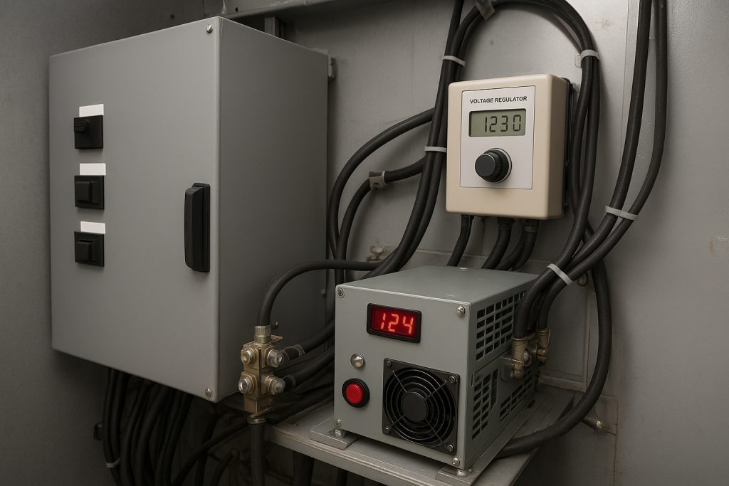
| Inspect electrical systems | Check for loose lugs and insulation wear |
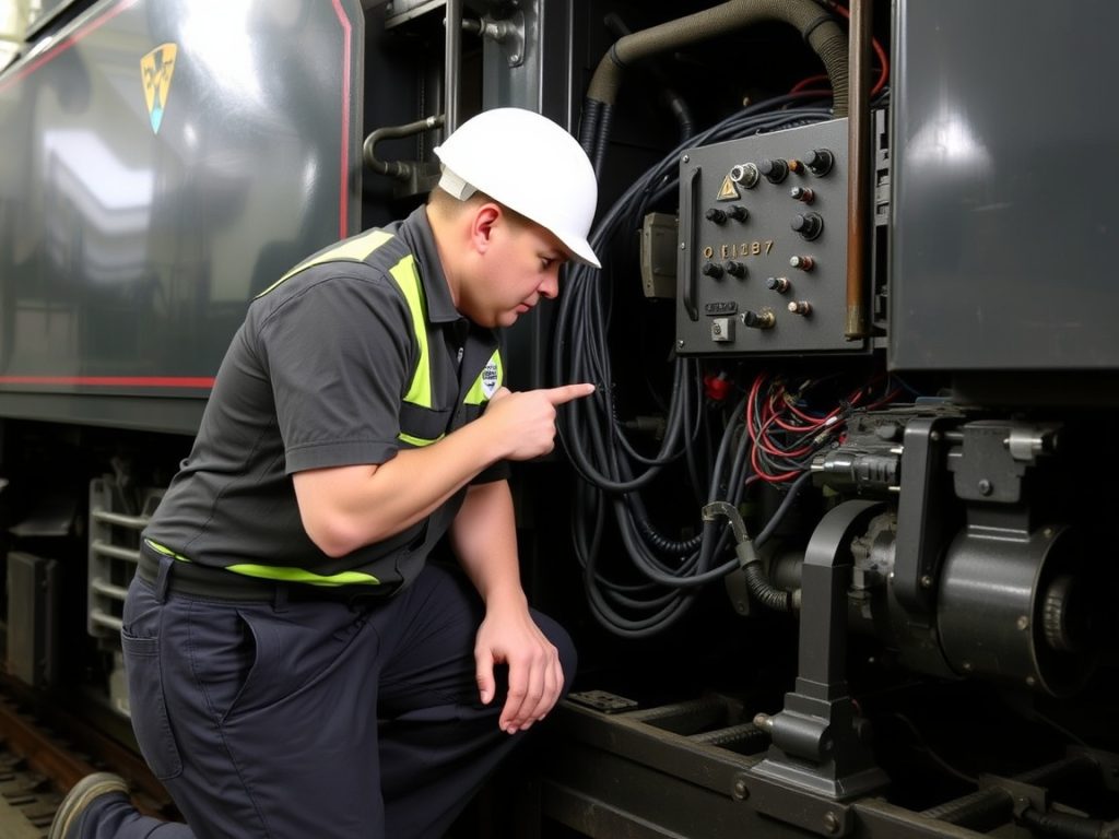
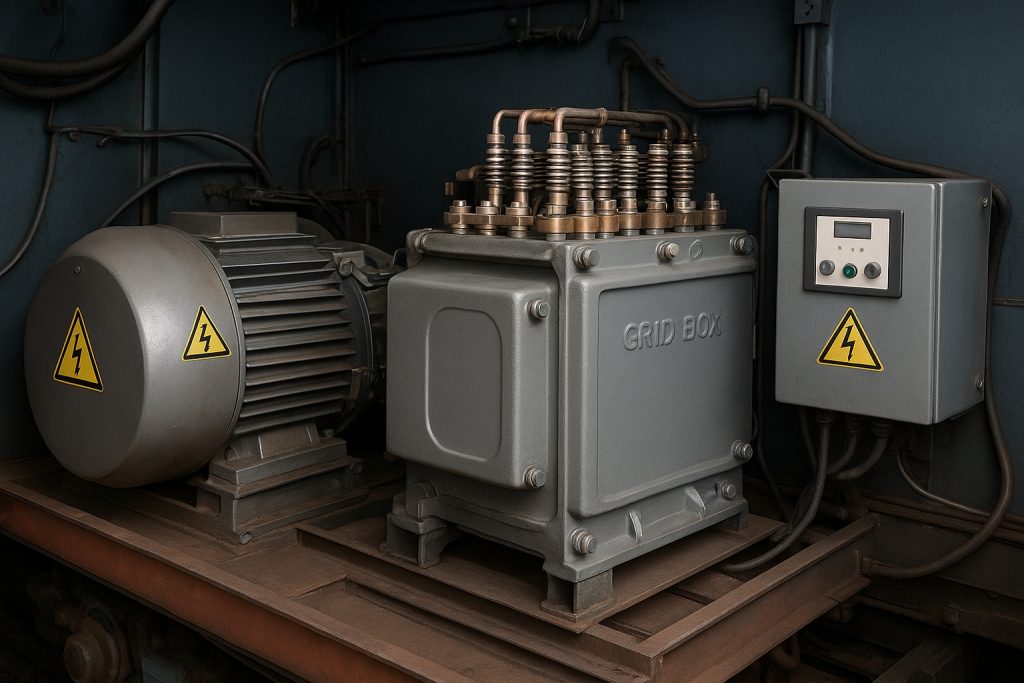
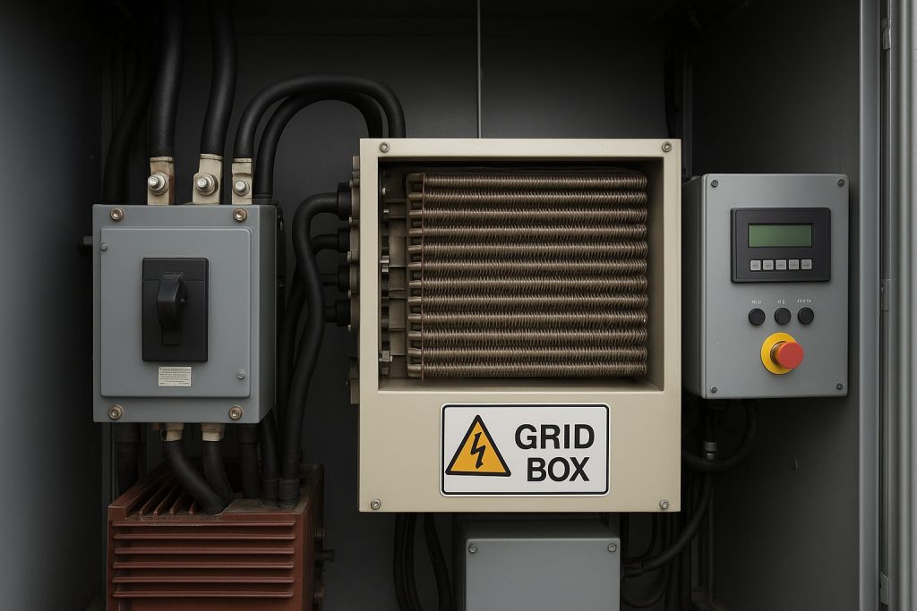
Introduction to Grid Boxes in EMD Diesel Locomotive Engines

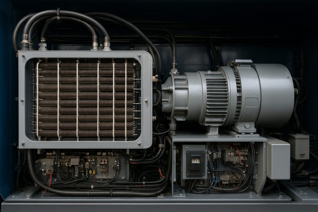
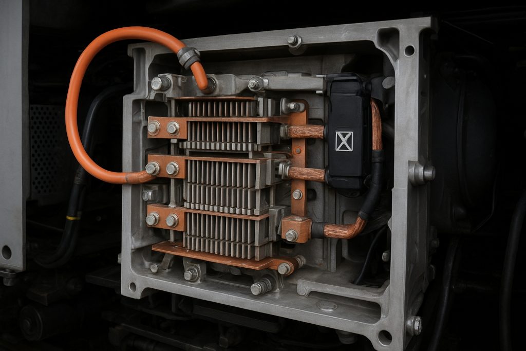
In an EMD diesel-electric locomotive, the grid box houses resistive elements that dissipate electric power during dynamic brake. Traction motors become generators, converting kinetic energy into electric power. The grid converts this electric power into heat, managing total energy consumption during descent and heavy freight service. Proper airflow, clean fins, and robust electrical connections preserve reliability and extend service life per locomotive, across freight and passenger operations.
Understanding the Grid Box Function
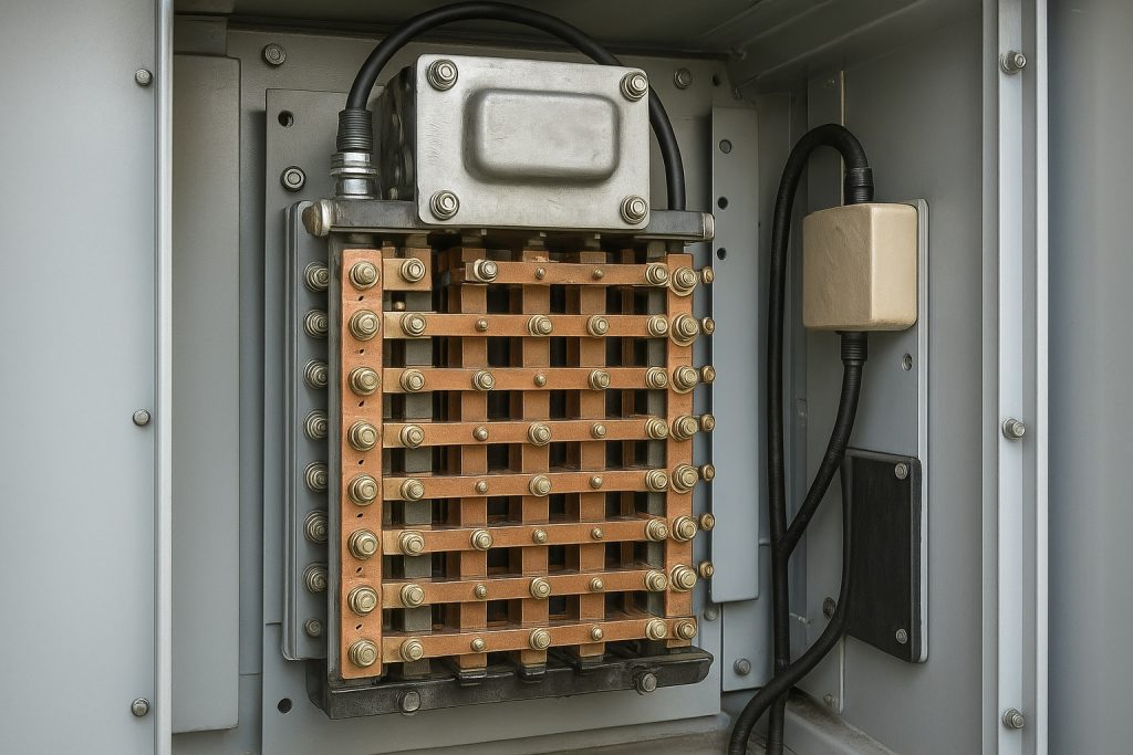
The grid box forms the core of the dynamic brake system in diesel locomotives. When a loco decelerates, each traction motor back-feeds electric power into the grids. The grids turn that energy into heat, controlled by fans and ducting. This protects the mechanical brake, reduces wear, and supports energy efficiency of diesel-electric systems. EMD grid designs balance resistance value, airflow, and thermal capacity to meet energy requirements on steep grades and long consists.
Main Pain Points Addressed
Operators struggle with unpredictable grid failures, soaring maintenance costs, and downtime during peak rail operation. Heat cracks elements, dust insulates fins, and weak fans spike temperatures. Mismatched overhaul schedules inflate costs. We provide actionable rebuild standards, inspection intervals, and sourcing guidance to stabilize life expectancy. Mikura International supports compliant components for EMD platforms, ensuring reliable spares for freight and passenger locomotives without disrupting existing power system strategies.
Importance of Life Expectancy in Locomotive Performance
Grid box life expectancy shapes fleet reliability and cost-effective deployment. Stable grids protect traction motors, brakes, and electrical systems, sustaining timetable integrity for freight and passenger trains. Extending lifespan reduces unexpected shop events and improves energy efficiency of diesel-electric operations. Coordinated rebuild practices align with prime mover and turbo service windows, optimizing the life span of each diesel engine asset and smoothing capital plans for rail operators managing mixed freight and passenger service.
Factors Affecting Lifespan of Grid Boxes

The lifespan of an EMD locomotive grid box depends on heat, duty cycle, and maintenance rigor. Material stability, airflow, and traction motor loading define stress. Harsh freight service, dust, and vibration accelerate wear. Misaligned overhaul plans shorten life expectancy. Smart inspection, rebuild timing, and electrical systems checks cut maintenance costs. Rail operators should match cooling capacity to energy requirements and track braking profiles per locomotive.
Material Quality and Manufacturing Standards
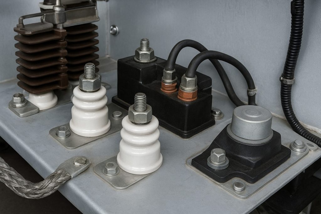
Grid element alloys must tolerate repeated thermal cycling without creep or cracking. High nickel-chrome content improves reliability under diesel-electric locomotives’ dynamic brake loads. Precision winding, uniform resistance, and tight tolerances prevent hot spots and arcing. Robust bus bars and braze joints limit voltage drop and electric power loss. Coatings resist corrosion in humid rail operation. Consistent QA, traceability, and test certificates ensure each rebuild meets EMD specification and service life targets across freight and passenger service.
Operating Conditions and Usage Patterns
Duty cycle sets the life span. Long downhill braking on a freight train pushes total energy consumption through the grid box. Stop‑start passenger service adds frequent thermal shocks. High ambient temperature raises energy consumed as heat and fan demand. Dust and corrosive air increase insulation and resistance drift. Mismatched consists can overload a loco’s traction motor set. Operators should log grade profiles, dynamic brake time, and airflow to forecast lifespan across 20–30 year locomotive service life.
Maintenance Practices and Their Impact
Clean grids run cooler and last longer. Scheduled inspections find cracked elements, loose lugs, and worn contactors before failure. IR thermography highlights imbalance in electrical systems under brake. Align grid box rebuild with prime mover and turbo overhaul to reduce downtime. Calibrate fans and verify ducts for cost-effective cooling. Replace corroded connectors to protect power system integrity. With disciplined procedures, rail operators lower maintenance costs and stabilize life expectancy per locomotive in freight and passenger operations.
Expected Lifespan of Grid Boxes in EMD Locomotives

EMD grid box lifespan depends on thermal cycling discipline, airflow, and duty profile. In typical freight service, expect 8–15 years before a scheduled rebuild. Passenger service may shorten intervals due to frequent brake events. Proper alignment with prime mover overhaul extends life expectancy and lowers maintenance costs. Clean electrical systems, balanced traction motor loading, and verified fans preserve reliability. Harsh dust, moisture, and corrosive exposure reduce life span. Smart monitoring helps rail operators meet energy requirements while protecting diesel-electric locomotives.
Average Lifespan Estimates
For an EMD diesel locomotive, average grid box life clusters in three bands. Units rebuilt with upgraded alloys and bus bars add one cycle. Aligning with 20–30 year service life requires two to three rebuilds. IR surveys, fan verification, and contactor testing push the upper bound. Clean grids sustain energy efficiency of diesel-electric operations.
| Service Type | Average Grid Box Life |
|---|---|
| Light freight | 12–15 years per locomotive |
| Mixed freight/passenger | 10–12 years |
| Heavy mountain freight | 8–10 years |
Comparative Analysis of Lifespan Across Models
Legacy EMD freight locomotives with axial fans show modest lifespan under heavy dynamic brake. New locomotive platforms with improved ducting extend intervals. Passenger locomotives face higher thermal shock but benefit from tighter electrical systems. Freight and passenger mixed fleets see variance by consist mass and grade. Compared with some GE peers, EMD grid architecture emphasizes serviceability and rebuild ease. When rail operators harmonize airflow and element resistance, lifespan converges. Duty cycle, not badge, drives total energy consumption through the grid.
Case Studies on Lifespan Variations
A mountain subdivision freight locomotive logged high dynamic brake hours and reached rebuild at nine years. After airflow upgrades and contactor refurbishment, the next cycle extended to twelve. A passenger service loco faced thermal fatigue from frequent stops, prompting an eight-year rebuild. Fan calibration and improved bus bar plating reduced heat rise by 12 percent. A coastal railroad battled corrosion; a sealing retrofit and scheduled washing stabilized resistance drift. These cases show disciplined maintenance cuts risk and preserves reliability.
Rebuilding Grid Boxes: Process and Benefits

Rebuilding restores reliability, trims maintenance costs, and matches the diesel engine overhaul window. The process replaces cracked resistive grids, renews insulators, and resurfaces bus bars. Fans, contactors, and wiring in the power system get tested and calibrated. Rail operators recover energy efficiency during dynamic brake by lowering hot spots. Rebuilds suit 20–30 year asset plans, especially in freight service. Mikura International supplies compliant components and rebuild kits for EMD platforms to ensure consistent specification and service life.
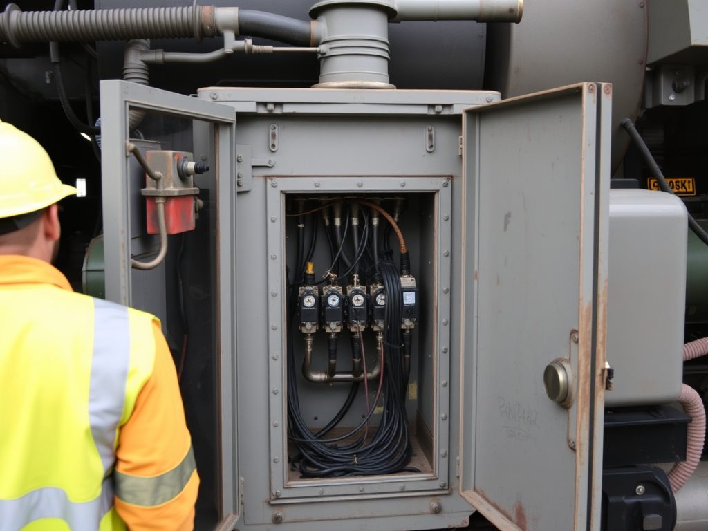
Overview of the Rebuild Process
Begin by isolating electrical systems and removing the grid box assembly. Inspect traction motor cabling and bus connections. Disassemble modules, measure resistance, and remove drifted elements. Install new alloy grids, renew insulators, and torque lugs to specification. Dress contact surfaces and test dielectric strength. Balance fan blades, verify airflow, and benchmark temperature rise at set electric power. Update wiring to meet insulation ratings related to emission standards. Finalize with IR thermography, vibration checks, and documentation for cost-effective rail operation.
| Task | Action |
|---|---|
| Electrical preparation | Isolate systems, remove grid box, inspect cabling and bus connections |
| Module service | Disassemble, measure resistance, remove drifted elements, install new alloy grids and insulators |
| Connections and surfaces | Torque lugs to spec and dress contact surfaces; test dielectric strength |
| Cooling and performance | Balance fan blades, verify airflow, benchmark temperature rise at set electric power |
| Compliance and verification | Update wiring for required insulation ratings; complete IR thermography, vibration checks, and documentation |
Cost-Benefit Analysis of Rebuilding vs. Replacement
Rebuilding costs 35–55 percent of new, depending on damage and parts scope. Replacement offers longer warranty but higher capital outlay. For a freight locomotive, a rebuild aligned with prime mover and turbo work slashes downtime. Energy consumed as heat drops after refurbishing airflow and connections. Passenger trains gain quick turnaround and standardized spares. Over 20–30 years, two rebuilds often beat one replacement on net present cost. Replacement suits severe corrosion or obsolete modules with scarce parts.
Expert Insights on Effective Rebuild Strategies
Schedule rebuilds by brake hours, not calendar age. Track dynamic brake energy per locomotive to forecast life span. Standardize resistance values across consists to balance traction. Cleanliness is performance; dust control extends lifespan. Verify contactor timing to cut arcing. Specify nickel-chrome grids and plated bus bars for corrosion control. Calibrate fans for target CFM and confirm duct sealing. Close the loop with post-rebuild data logging. Mikura International recommends aligning grid work with engine overhaul to lower maintenance costs.
Maintenance Tips for Prolonging Grid Box Lifespan
Extending grid box lifespan in an EMD diesel locomotive starts with disciplined practices. Focus on heat control, airflow, and clean electrical systems. Match rebuild timing to overhaul events on the prime mover and turbo. Track dynamic brake energy consumed per locomotive. Use quality resistive elements and robust bus bars. Standardize inspections across rail operation. Align parts with emission standards. Target cost-effective actions that reduce maintenance costs and protect traction motor health. These steps stabilize life expectancy in freight service and passenger service.
Routine Inspections and Maintenance Checks
Set inspection intervals by brake hours and duty cycle. Use IR thermography after long freight train descents to spot hot grids. Verify fan CFM, duct sealing, and filters to protect airflow. Torque-test lugs and bus bars to stop arcing in electrical systems. Inspect insulators and contactors for carbon tracking. Measure resistance drift against EMD specification. Clean dust from fins to lower total energy consumption as heat. Record traction motor currents during dynamic brake. Document findings per locomotive to forecast life span accurately.
Best Practices for Maintenance Costs Management
Bundle grid service with diesel engine overhaul windows to cut downtime. Stock standardized grid elements to streamline rebuild tasks. Track electric power throughput and thermal cycles to predict lifespan. Use condition-based triggers for loco entry to the shop. Negotiate volume buys for insulators and bus bars to lower maintenance costs. Apply failure mode data to prioritize actions that boost reliability. Calibrate fans before peak seasons. Keep spares aligned with emission standards. These steps keep rail operators cost-effective while sustaining service life.
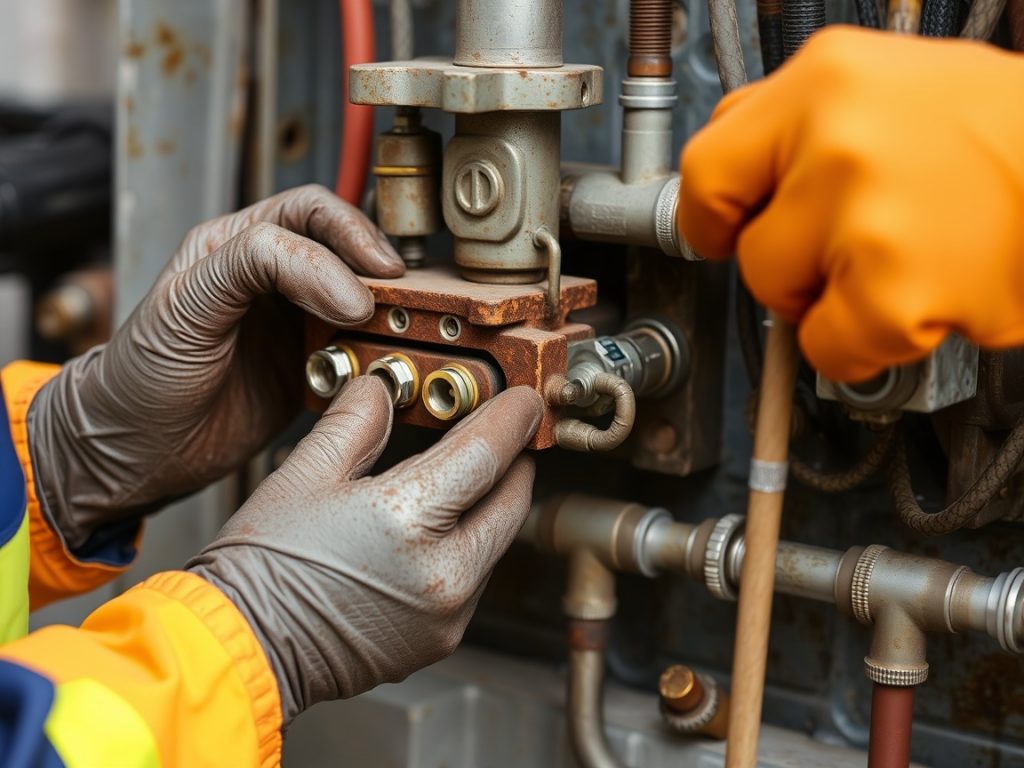
Utilizing Quality Parts for Repairs
Select nickel-chrome grid alloys rated for repeated thermal cycling on diesel-electric locomotives. Specify plated bus bars for corrosion control in harsh railroad environments. Choose insulators with proven dielectric strength and emission compliance. Verify compatibility with the loco power system and traction motor connectors. Avoid mixed resistance values across modules. Test new components under target electric power and airflow. Mikura International supplies quality EMD-compatible parts that meet energy requirements. Using reputable components reduces rework, improves reliability, and extends life expectancy per locomotive.
Conclusion: Maximizing Performance and Lifespan

Maximizing grid box lifespan hinges on airflow, cleanliness, and precise electrical systems work. Monitor dynamic brake duty on freight and passenger operations. Align rebuild timing with prime mover and turbo overhaul to capture savings. Track energy consumed and temperature rise to target interventions. Use IR surveys to find hot spots early. Select quality parts and maintain documentation per locomotive. These actions protect traction motors, reduce maintenance costs, and preserve the energy efficiency of diesel-electric fleets over a 20–30 year service life.
Summarizing Key Takeaways
Plan inspections by brake hours, not calendar time. Keep fins clean and fans calibrated to manage heat. Tighten lugs and replace corroded bus bars to avoid arcing. Standardize resistance values to balance traction across consists. Bundle rebuild with diesel engine overhaul for cost-effective downtime. Log electric power and temperature during dynamic brake events. Use quality EMD-specified parts to ensure reliability. Maintain records per locomotive to refine life span predictions. These steps stabilize grid performance in freight service and passenger trains.
Future Considerations for EMD Locomotive Owners
Adopt continuous monitoring of traction motor current and grid temperatures. Consider upgraded ducting on legacy freight locomotive platforms. Evaluate new locomotive fan technologies that deliver steadier airflow. Integrate analytics that relate duty cycle to lifespan forecasts. Ensure parts comply with evolving emission standards and insulation ratings. Plan spares strategies that support rapid rebuild turnaround. Mikura International can assist with sourcing strategies and standardization. Investing in predictive tools now will reduce risk and improve reliability across the diesel-electric fleet.
Final Thoughts on Lifespan and Maintenance
Grid box life expectancy is manageable with data and disciplined practice. Control heat, airflow, and cleanliness to extend service life. Match rebuild cadence to overhaul cycles to lower maintenance costs. Use components that meet EMD specification and energy requirements. Record total energy consumption and temperature rise per locomotive. These fundamentals protect the power system and traction motors. Rail operators that execute consistently will realize longer lifespan, fewer shop events, and stable performance on both freight and passenger service corridors.