TL;DR
- Critical Protection: The Turbo Soak Back Pump 40182032 provides essential auxiliary lubrication for EMD locomotive engines, circulating filtered oil for 30, 35 minutes after shutdown to prevent heat-induced damage.
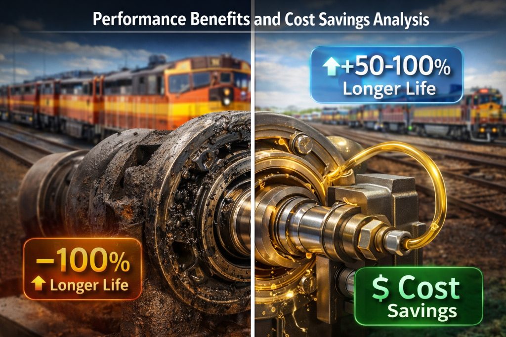
- Fuel Efficiency & Reliability: By preventing “oil coking” (the buildup of hard carbon deposits), the pump maintains peak turbocharger performance, which directly reduces fuel consumption and prevents costly unplanned downtime.
- Component Longevity: The system ensures bearings are pre-lubricated before startup and cooled post-shutdown, effectively preventing shaft seizure, bearing degradation, and thermal breakdown of the oil.
- Maintenance Best Practices: For optimal results, operators should follow strict installation procedures, monitor oil pressure regularly, and adhere to filter replacement schedules to protect the turbocharger’s rotating assembly.
Turbo Soak Back Pump 40182032 and Fuel Efficiency
Locomotive maintenance managers often face significant challenges. Premature turbocharger failure is a major concern. This leads to costly repairs and unexpected downtime. These issues severely impact operational efficiency and budget. Mikura International understands these pain points.
- Implement a strict maintenance schedule.
- Monitor turbocharger performance regularly.
- Ensure proper lubrication systems are active.
- Address any warning signs immediately.
- Use high-quality replacement parts.
- Train staff on best practices.
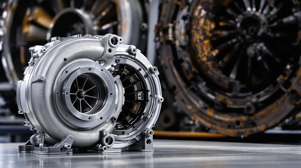
Function and Role of Turbo Soak Back Pump 40182032
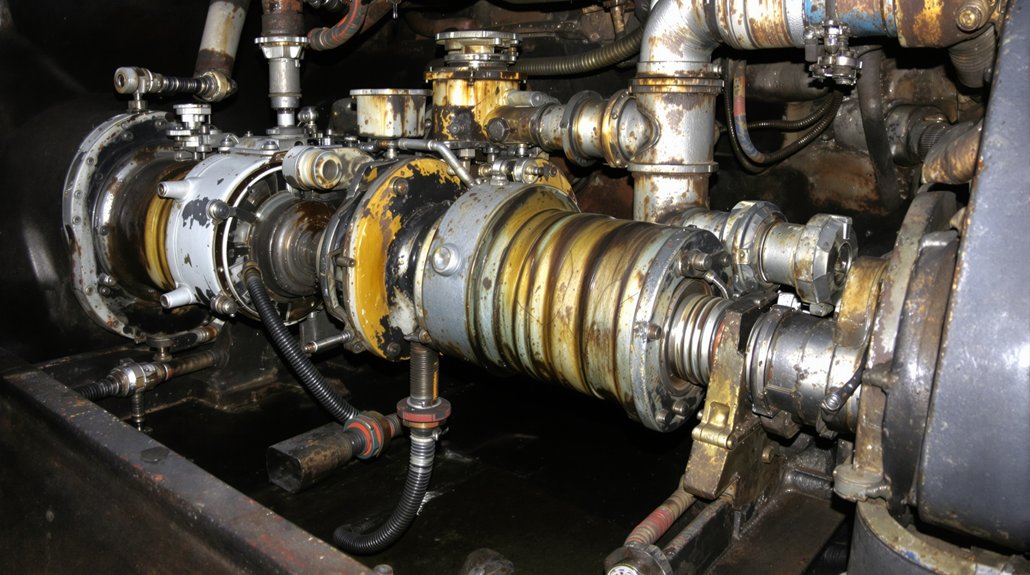
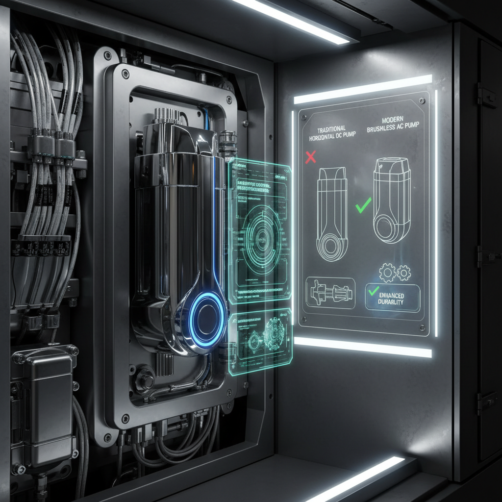
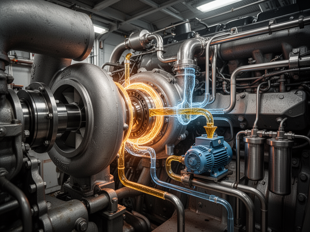
The Turbo Soak Back Pump 40182032 is an auxiliary lubrication system. It is vital for locomotive maintenance. This pump circulates filtered oil post-engine shutdown. This process significantly reduces oil coking. Reduced coking directly impacts fuel efficiency. It maintains optimal turbocharger performance.
This critical component supports EMD locomotive engines. It ensures the turbine wheel and rotating assembly remain lubricated. The pump prevents thermal breakdown. It extends the life of bearing assemblies. This proactive measure is key for engine reliability.
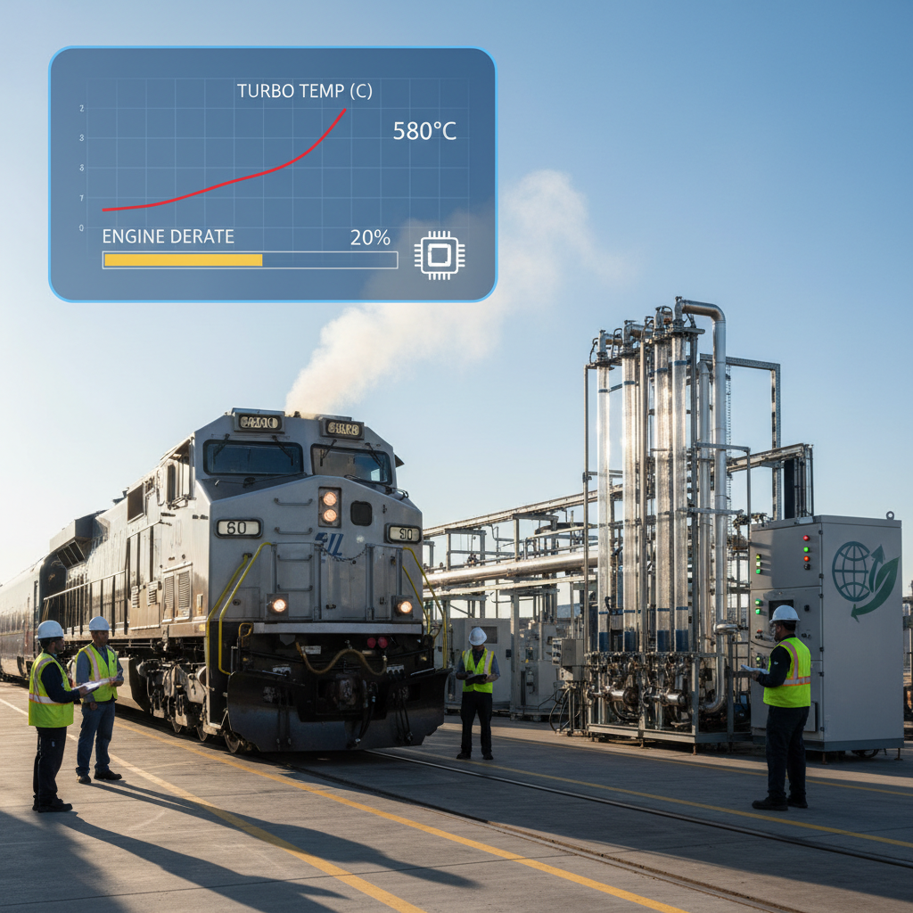
Impact of Oil Coking on Locomotive Fuel Efficiency
Oil coking is a severe problem. It causes bearing degradation within the turbocharger. This degradation decreases turbocharger efficiency. Consequently, increased fuel consumption occurs. It also leads to unplanned downtime and costly repairs.
Preventing oil coking is crucial. The Turbo Soak Back Pump 40182032 achieves this. It improves engine reliability and operational efficiency. Mikura International provides solutions to combat coking. This ensures sustained fuel efficiency for diesel locomotives.
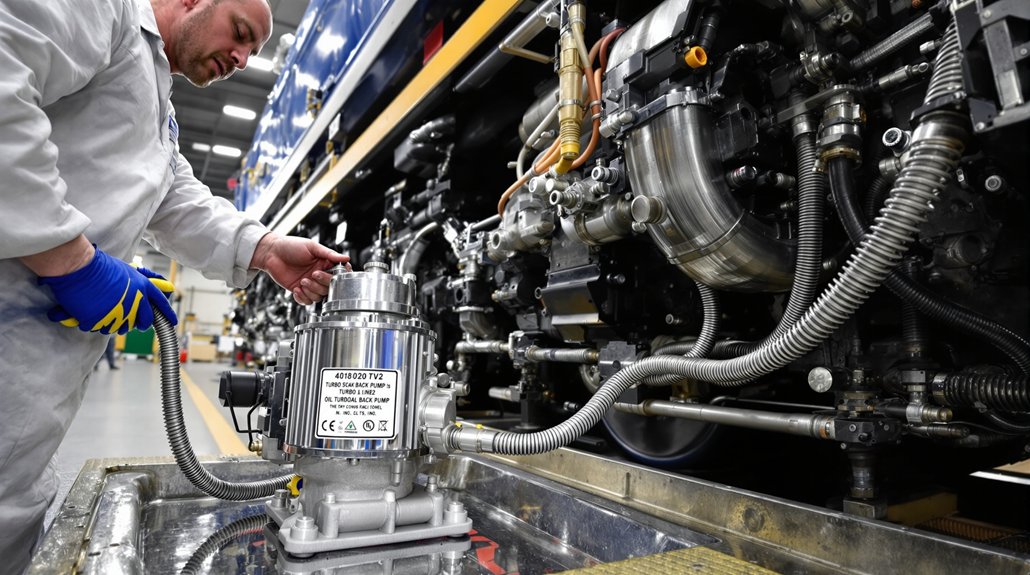
Installation and Inspection Procedures for the Soak Back Pump
Proper installation of the Turbo Soak Back Pump 40182032 is essential. Begin with a preliminary inspection. Check the Soak Back Filter and all piping. Verify electric motor functionality. Ensure correct mounting of the pump unit. Route oil lines properly.
Specific torque values are critical. Use recommended line diameters. These steps ensure optimal operation. Regular inspection of the check valve testing is also vital. This prevents future issues with bearing lubrication. Mikura International provides expert guidance.
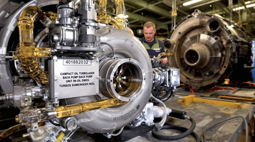
Operational Control and Automatic System Integration
The Turbo Soak Back Pump 40182032 operates automatically. The locomotive control computer manages it. It activates during engine shutdown cycles. The pump runs for 30-35 minutes. This prevents thermal buildup in the turbocharger. Maintaining turbocharger efficiency is paramount.
This automated process protects the rotating assembly. It ensures proper bearing lubrication. The system integrates seamlessly with the main lubrication system. This prevents oil oxidation and hydrocarbon cracking. It is a smart solution for locomotive maintenance.
Pre-startup Lubrication and Post-shutdown Cooling Cycles
Activating the Turbo Soak Back Pump 40182032 before startup is beneficial. This ensures bearings are pre-lubricated. Pre-lubrication reduces wear significantly. Post-shutdown circulation is equally important. It prevents heat-induced oil cracking and coking.
This continuous oil circulation preserves component longevity. It protects the main oil gallery. The process ensures the bearing clearance remains optimal. It prevents shaft seizure. This extends turbocharger service intervals.
Effects of Oil Coking on Bearing and Turbocharger Life
Oil coking causes severe damage. It leads to carbon deposits on bearing assemblies. This results in scoring and potential shaft seizure. These issues drastically shorten turbocharger life. They increase unplanned downtime.
Maintaining continuous oil circulation minimizes these damages. The Turbo Soak Back Pump 40182032 achieves this. It reduces thermal and mechanical wear. This extends turbocharger service life. It keeps the rotating assembly in prime condition.
Benefits of Continuous Oil Circulation Post-Shutdown
Continuous oil circulation post-shutdown offers significant benefits. It reduces thermal stress on turbo bearings. This prevents carbon buildup. It sustains optimal fuel efficiency over time. Studies indicate improved engine reliability.
The Turbo Soak Back Pump 40182032 ensures this circulation. It keeps oil temperatures below the thermal stability threshold. This prevents oil coking. It protects vital bearing assemblies. Mikura International supports enhanced component longevity.
Related Innovation
Function and Role of Turbo Soak Back Pump 40182032
The Turbo Soak Back Pump 40182032 is a vital component. It operates as an auxiliary lubrication system. This system functions after engine shutdown. It circulates filtered oil to the turbocharger bearings. This action significantly reduces oil coking. Oil coking is a primary cause of turbocharger degradation. Preventing coking maintains optimal turbocharger performance. This directly enhances EMD locomotive engines fuel efficiency. The pump ensures continuous lubrication during critical cooling phases. This extends the service life of the turbocharger. It also contributes to overall engine reliability in EMD locomotive engines.
Impact of Oil Coking on Locomotive Fuel Efficiency
Oil coking directly harms locomotive fuel efficiency. It causes deposits on bearing assemblies. These deposits lead to increased friction and wear. This degrades turbocharger efficiency over time. A less efficient turbocharger means the engine works harder. This results in higher fuel consumption. It also causes increased emissions. Oil coking shortens the lifespan of critical components. This necessitates more frequent maintenance. It also leads to expensive repairs and unplanned downtime. The Turbo Soak Back Pump 40182032 actively prevents this. It maintains cleaner bearings. This ensures the turbocharger operates at peak efficiency. This directly translates to improved fuel economy.
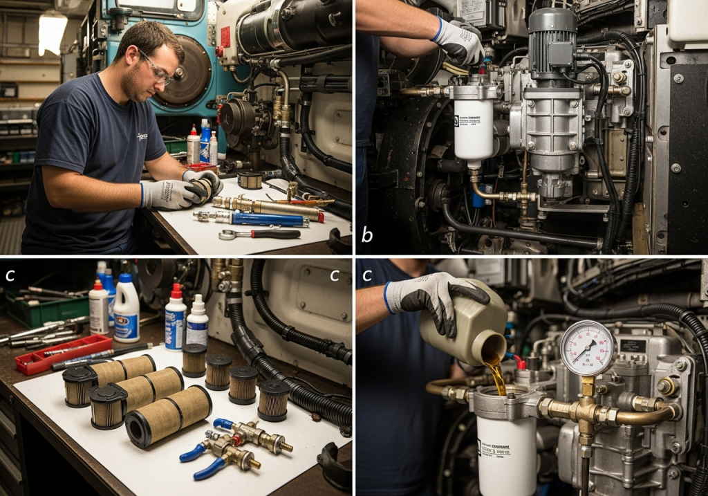
Installation and Inspection Procedures
Proper installation of the Turbo Soak Back Pump 40182032 is critical. It ensures long-term locomotive maintenance success. Before installation, perform preliminary inspections. Check the soak back filter and piping for damage. Verify the integrity of the oil gallery network. Ensure all connections are clean and secure. Mount the pump according to manufacturer specifications. Route oil lines carefully to avoid kinks. Use correct torque values for all fasteners. Recommended line diameters must be used. These steps ensure optimal operation. Mikura International provides detailed guides for installation. Always follow these procedures for best results. This prevents costly unplanned downtime.
Operational Control and Automatic System Integration
The Turbo Soak Back Pump 40182032 integrates seamlessly. It connects with the locomotive’s control system. This ensures robust Turbocharger management. It activates automatically during engine shutdown cycles. This activation lasts for approximately 30-35 minutes. This timing is critical for preventing thermal buildup. The auxiliary cooling system circulates oil. This process cools the hot turbocharger bearing assemblies. This prevents thermal breakdown of the oil. This automatic operation requires no manual intervention. It ensures consistent protection. The locomotive control computer manages this system. Proper integration is key to maintaining turbocharger efficiency and Engine reliability.
Automated Auxiliary Cooling System Operation
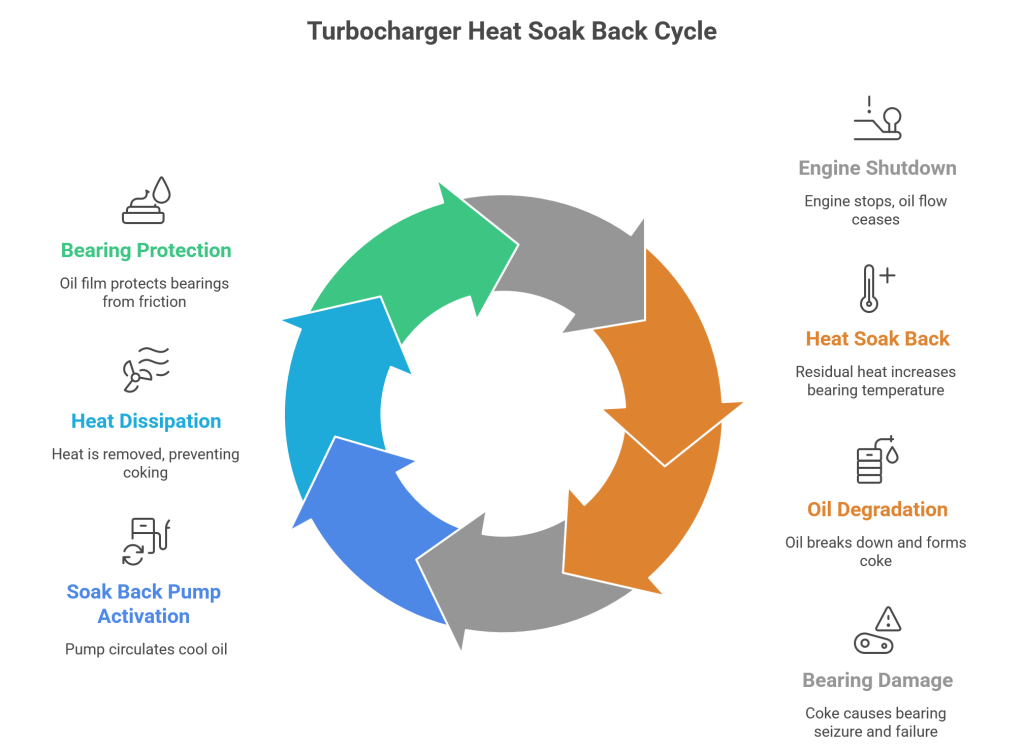
The Turbo Soak Back Pump 40182032 functions as a vital auxiliary lubrication system. It activates automatically. This occurs immediately after the Diesel Prime Mover shuts down. The system circulates pressurized oil. This oil flows through the turbine wheel and bearing assemblies. This continuous flow prevents oil coking. Oil coking forms damaging carbon deposits. These deposits occur when residual heat bakes stagnant oil. Preventing this coking is crucial. It directly impacts locomotive fuel efficiency. Maintaining clean bearing clearances is essential. This extends the service intervals for EMD locomotive engines.
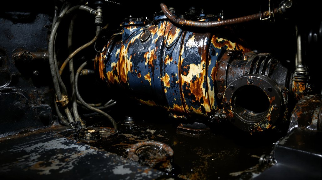
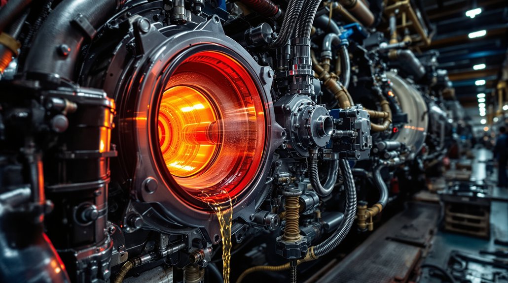
Preventing Thermal Breakdown and Carbon Deposits
Engine shutdown cycles generate significant residual heat. This heat concentrates in the turbocharger. Without the Turbo Soak Back Pump 40182032, oil stagnates. It reaches its thermal stability threshold. This causes rapid oil oxidation and hydrocarbon cracking. The result is harmful carbon deposits and thermal breakdown. These deposits adhere to bearing surfaces. They lead to increased friction and wear. This compromises the rotating assembly. Mikura International emphasizes preventing these issues. Continuous oil circulation post-shutdown is vital. It maintains bearing lubrication and cools components. This significantly reduces unplanned downtime.
Role of the Locomotive Control Computer
The locomotive control computer is central. It manages the Turbo Soak Back Pump 40182032. This computer monitors engine parameters. It initiates the soak back cycle precisely. This ensures the 30-35 minute run time. This duration is engineered for optimal cooling. It prevents heat-induced oil cracking. The system also performs check valve testing. This ensures proper oil flow. Effective integration maintains the main lubrication system integrity. It extends component longevity. This smart control prevents shaft seizure. It protects the critical bearing assemblies.
Benefits of Continuous Oil Circulation Post-Shutdown
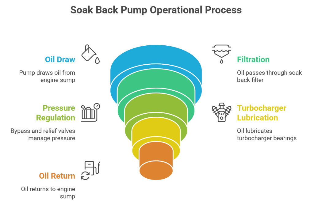
Maintaining oil flow after shutdown offers significant benefits. It reduces thermal stress on turbo bearings. This prevents carbon buildup. This sustains optimal locomotive fuel efficiency over time. Studies indicate this practice extends turbocharger service life. It minimizes damages from thermal and mechanical wear. The Turbo Soak Back Pump 40182032 ensures this circulation. It draws oil from the oil gallery network. It filters it through the Soak Back Filter. This delivers clean oil to the bearing assemblies. This pre-lubrication also aids startup. It reduces initial wear. This protects your investment in EMD locomotive engines.
Pre-startup Lubrication and Post-shutdown Cooling Cycles
The Turbo Soak Back Pump 40182032 performs two vital functions. It ensures engine reliability. This pump prevents unplanned downtime.
Before engine startup, the Turbo Soak Back Pump 40182032 provides critical pre-lubrication to the bearing assemblies. This reduces wear during initial engine rotation. It prepares the rotating assembly for operation. This action prolongs component longevity for the diesel prime mover.
Post-shutdown, the pump maintains essential oil circulation. This prevents heat-induced oil cracking. It stops oil coking. This continuous flow after shutdown minimizes thermal stress on the turbine wheel and bearing assemblies. It is a key aspect of Turbocharger Lubrication.
The auxiliary lubrication system ensures the main lubrication system remains primed. This prevents dry starts. It protects critical components. This dual action significantly extends the service intervals of EMD locomotive engines.
This process is crucial for preventing Carbon deposits. It maintains Bearing clearance. It ensures the thermal stability threshold of the oil is not breached. Mikura International emphasizes these benefits.
Studies indicate that continuous oil flow after shutdown significantly reduces thermal stress on turbo bearings. This prevents carbon buildup. It sustains optimal fuel efficiency over time. This extends the turbocharger’s service life.
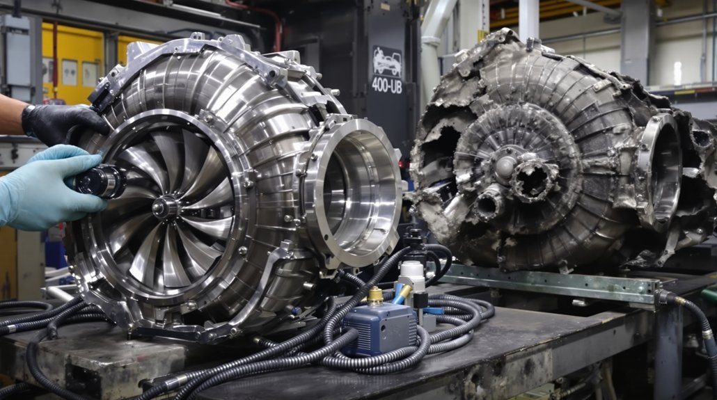
Effects of Oil Coking on Bearing and Turbocharger Life
Oil coking severely impacts bearing and turbocharger life. It forms hard carbon deposits on bearing surfaces. These deposits cause scoring and increased friction. This can lead to premature wear. In severe cases, it causes shaft seizure. This necessitates costly turbocharger replacement. The Turbo Soak Back Pump 40182032 mitigates these risks. It ensures continuous oil circulation. This prevents carbon buildup. This action reduces thermal and mechanical wear. It extends the turbocharger’s service life significantly. This protects your investment and reduces maintenance costs.
Impact of Oil Coking on Locomotive Fuel Efficiency
Oil coking directly impacts locomotive fuel efficiency. Bearing degradation from coking decreases turbocharger efficiency. This leads to increased fuel consumption. It also causes costly unplanned downtime. Preventing oil coking with the Turbo Soak Back Pump 40182032 improves engine reliability. It sustains optimal operational efficiency. This pump reduces thermal stress on turbo bearings. It prevents carbon deposits. This helps maintain consistent fuel efficiency over time.
Benefits of Continuous Oil Circulation Post-Shutdown
Maintaining oil flow after engine shutdown is crucial. The Turbo Soak Back Pump 40182032 provides this continuous circulation. It reduces thermal stress on turbo bearings. This prevents carbon buildup. It also minimizes oil oxidation and hydrocarbon cracking. This action sustains optimal fuel efficiency. It extends the service intervals for EMD locomotive engines. This proactive measure prevents costly repairs. It ensures longer component longevity for the rotating assembly.
Understanding Thermal Breakdown and Carbon Deposits
Thermal breakdown of oil is a primary cause of carbon deposits. High temperatures in the turbine wheel area lead to oil coking. When the main lubrication system shuts down, residual heat remains. This heat exceeds the oil’s thermal stability threshold. The Turbo Soak Back Pump 40182032 circulates cooler oil. This prevents localized overheating. It flushes away potential carbon-forming particles. This protects the bearing assemblies from damage. Mikura International emphasizes preventing thermal breakdown for optimal performance.
Benefits of Continuous Oil Circulation Post-Shutdown
Continuous oil circulation after engine shutdown offers critical advantages. It significantly reduces thermal stress on turbo bearings. This action prevents the formation of harmful carbon deposits. These deposits are a primary cause of premature wear. The Turbo Soak Back Pump 40182032 is essential here. It ensures critical bearing lubrication.
Preventing Thermal Breakdown and Carbon Deposits
Continuous circulation helps dissipate residual heat from the turbine wheel. This protects the oil from thermal breakdown. It maintains oil quality within the main lubrication system. This sustained protection helps the turbocharger perform optimally. This directly contributes to consistent fuel efficiency. Mikura International emphasizes this critical advantage.
Studies show this practice extends turbocharger life. It minimizes the need for unscheduled maintenance. This reduces unplanned downtime for diesel locomotive engines. The auxiliary lubrication system prevents hydrocarbon cracking. This protects the rotating assembly.
Impact of Oil Coking on Locomotive Fuel Efficiency
Oil coking severely impacts locomotive fuel efficiency. It leads to bearing degradation within the turbocharger. This decreases overall turbocharger efficiency. In turn, this causes increased fuel consumption. Preventing coking with the Turbo Soak Back Pump 40182032 improves reliability. It enhances operational efficiency. The pump maintains the thermal stability threshold of the oil. This prevents carbon deposits from forming. These deposits restrict oil flow within the oil gallery network.
Effects of Oil Coking on Bearing and Turbocharger Life
Oil coking causes hard carbon deposits on bearing surfaces. These deposits lead to scoring and increased friction. This accelerates premature wear of bearing assemblies. In severe cases, it can cause shaft seizure. This necessitates costly turbocharger replacement. The Turbo Soak Back Pump 40182032 mitigates these risks. It ensures continuous oil circulation. This prevents carbon buildup. This action reduces thermal and mechanical wear. It extends the service intervals for EMD locomotive engines.
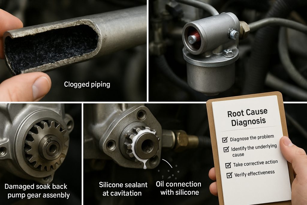
Expert Insight
“Turbo soak-back pumps are essential for maintaining the thermal stability threshold of the oil immediately upon engine shutdown; by ensuring continuous circulation, they prevent oil from being burnt and baked to the shaft, effectively avoiding the hard carbon deposits and coking that lead to expensive bearing degradation and turbocharger failure.” , Heavy-Duty Equipment Engineering Specialist
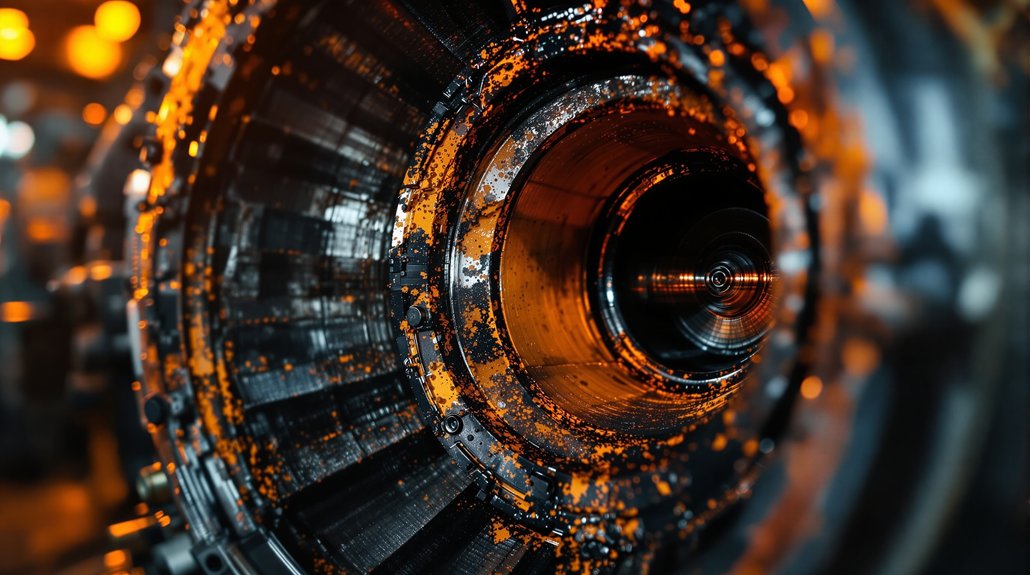
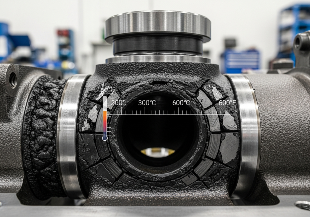
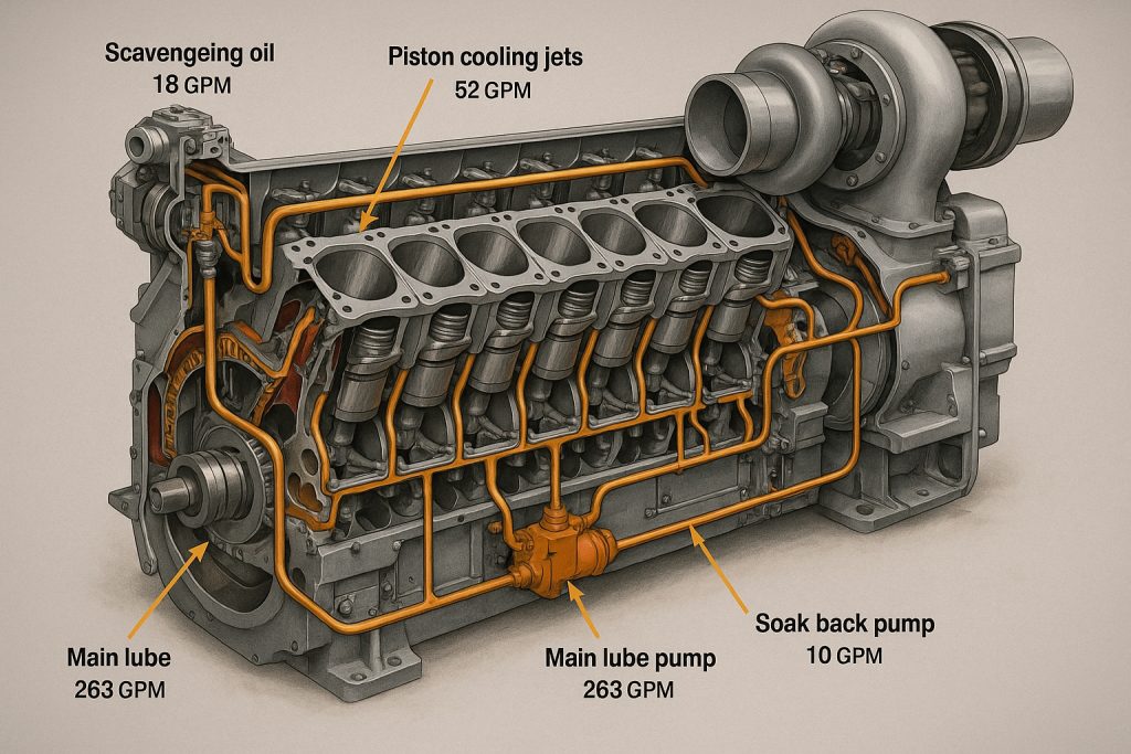
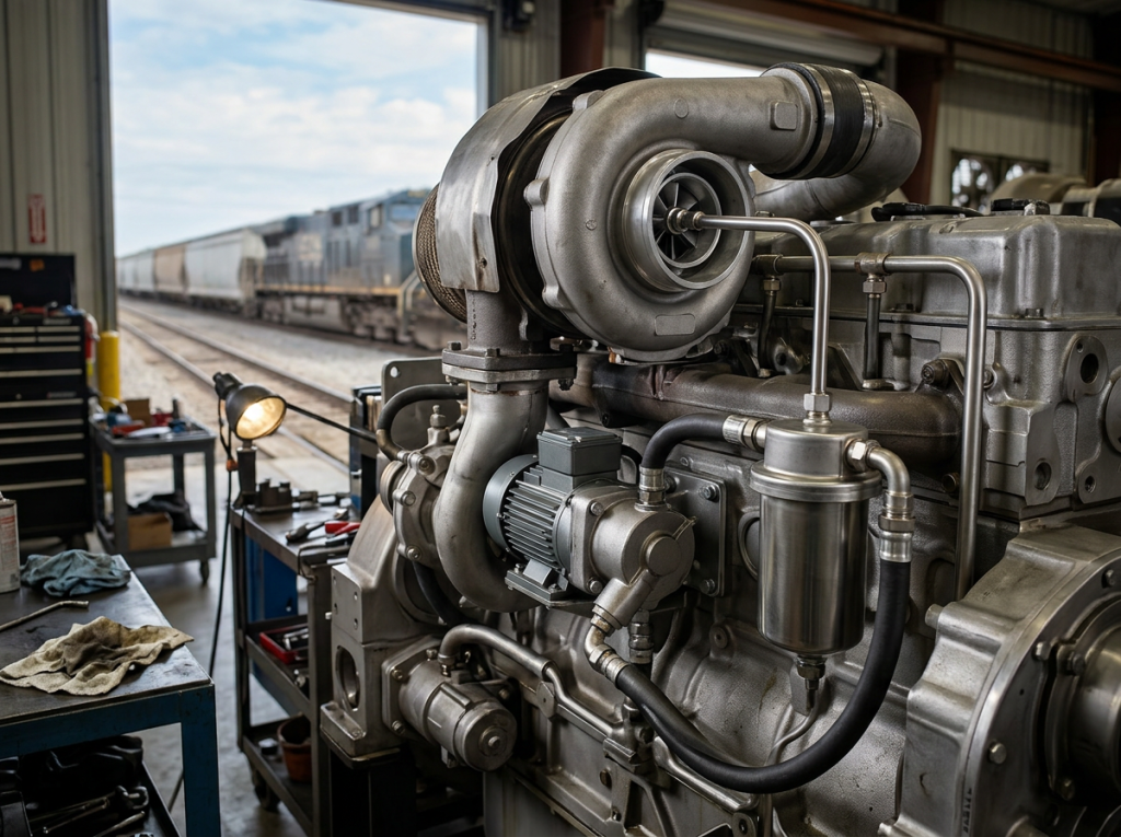
Understanding Turbocharger Lubrication
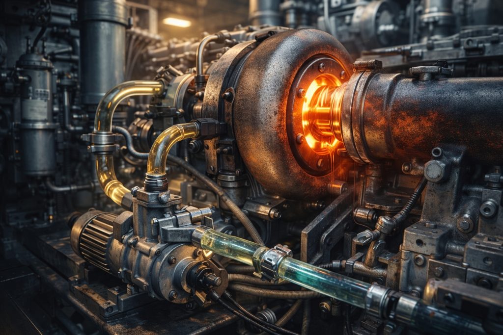
Turbochargers operate at extreme temperatures. Their bearings require constant, clean oil. The main lubrication system provides pressurized oil. This occurs during engine operation. Oil flows through an intricate oil gallery network. After engine shutdown, the main lube pump stops. Residual heat can then cause oil to bake onto hot surfaces. This leads to oil coking. This is where the Turbo Soak Back Pump 40182032 becomes indispensable. It ensures vital lubrication continues. This protects against thermal breakdown. It safeguards the entire rotating assembly. Proper bearing lubrication is key to engine reliability.
Function and Role of Turbo Soak Back Pump 40182032
The Turbo Soak Back Pump 40182032 functions as an auxiliary lubrication system. It circulates filtered oil post-shutdown. This significantly reduces oil coking. It maintains peak turbocharger performance. This directly impacts locomotive fuel efficiency. The pump ensures continuous flow. This prevents heat-induced damage to critical bearing assemblies. Mikura International provides reliable components for this system.
Impact of Oil Coking on Locomotive Fuel Efficiency
Oil coking causes rapid bearing degradation. This decreases turbocharger efficiency. It leads to increased fuel consumption. It also results in costly unplanned downtime. Preventing coking with the Turbo Soak Back Pump 40182032 improves reliability. It enhances operational efficiency. This protects your investment in diesel locomotive engines. It extends component longevity for critical parts like the turbine wheel.
Preventing Thermal Breakdown and Carbon Deposits
Continuous oil circulation after engine shutdown offers critical advantages. It significantly reduces thermal stress on turbo bearings. This action prevents the formation of harmful carbon deposits. These deposits are a primary cause of premature wear. The Turbo Soak Back Pump 40182032 is essential here. It ensures critical bearing lubrication. This safeguards the entire rotating assembly. It maintains the thermal stability threshold of the oil. This prevents hydrocarbon cracking and oil oxidation.
Common Pain Points and Solutions
Spare parts sourcing managers face significant challenges. Finding reliable components is often difficult. Ensuring timely delivery presents another hurdle. Dealing with unexpected component failures is a common pain point. The Turbo Soak Back Pump 40182032 directly addresses these issues. It significantly reduces turbocharger failures. This lowers costly unplanned downtime. Mikura International guarantees on-time delivery of quality parts. Our focus is on solving your operational problems. We provide solutions that enhance engine reliability. This helps manage service intervals effectively. We ensure your EMD locomotive engines run efficiently.
| Feature | Without Soak Back Pump | With Turbo Soak Back Pump 40182032 |
|---|---|---|
| Oil Coking Risk | High | Low |
| Turbocharger Lifespan | Reduced | Extended |
| Fuel Efficiency | Compromised | Maintained / Improved |
| Bearing Wear | Significant | Minimal |
| Unplanned Downtime | Frequent | Reduced |
| Maintenance Costs | Higher | Lower |
| Engine Reliability | Lower | Higher |
Function and Role of Turbo Soak Back Pump 40182032
The Turbo Soak Back Pump 40182032 is an auxiliary lubrication system. It operates after engine shutdown. This pump circulates filtered oil. Its primary role is to reduce oil coking. This directly impacts locomotive fuel efficiency. Maintaining turbocharger performance is key. The pump prevents residual heat from damaging bearing assemblies.
Impact of Oil Coking on Locomotive Fuel Efficiency
Oil coking leads to severe bearing degradation. This decreases turbocharger efficiency. Degraded turbochargers cause increased fuel consumption. This results in costly unplanned downtime. Preventing coking with the soak back pump improves reliability. It enhances overall operational efficiency. This protects your diesel locomotive investment.
Installation and Inspection Procedures
Proper installation procedures are critical. Begin with a preliminary inspection. Check filters, piping, and the electric motor functionality. Ensure correct mounting of the Turbo Soak Back Pump 40182032. Route oil lines precisely. Adhere to specific torque values. Use recommended line diameters. This ensures optimal operation and component longevity.
Operational Control and Automatic System Integration
The Turbo Soak Back Pump 40182032 integrates automatically. The locomotive control computer manages its activation. It engages during engine shutdown cycles. The pump typically runs for 30-35 minutes. This prevents thermal buildup. This is essential for maintaining turbocharger efficiency. It safeguards the rotating assembly.
Pre-startup Lubrication and Post-shutdown Cooling Cycles
Activating the Turbo Soak Back Pump 40182032 before startup is beneficial. It ensures bearing lubrication is established. This reduces initial wear on bearing assemblies. Post-shutdown circulation is equally vital. It prevents heat-induced oil oxidation. This stops hydrocarbon cracking and carbon deposits. This maintains the thermal stability threshold.
Effects of Oil Coking on Bearing and Turbocharger Life
Oil coking causes damaging deposits. It leads to scoring and potential shaft seizure. Maintaining continuous oil circulation minimizes these damages. This is achieved by the Turbo Soak Back Pump 40182032. It extends turbocharger service life. It reduces thermal and mechanical wear. This preserves bearing clearance.
Benefits of Continuous Oil Circulation Post-Shutdown
Maintaining oil flow after shutdown reduces thermal stress. This protects turbo bearings. It prevents carbon buildup. Studies show this sustains optimal fuel efficiency over time. The auxiliary cooling system supports this. This ensures the main lubrication system remains effective. The pump draws from the main oil gallery.
Maintaining Optimal Thermal Stability Threshold
The thermal stability threshold of lubricating oil is crucial. High temperatures after engine shutdown can exceed this threshold. This causes oil to degrade. It forms carbon deposits. These deposits lead to hydrocarbon cracking. The Turbo Soak Back Pump 40182032 prevents this. It circulates cooler oil. This keeps bearing assemblies temperatures below critical levels. It protects the oil’s integrity. It ensures effective lubrication. Maintaining this threshold is vital. It preserves component longevity. It sustains peak turbocharger management. This supports locomotive fuel efficiency.
Function and Role of Turbo Soak Back Pump 40182032
The Turbo Soak Back Pump 40182032 acts as an auxiliary lubrication system. It significantly reduces oil coking. It circulates filtered oil post-shutdown. This maintains turbocharger performance. Ultimately, this directly impacts locomotive fuel efficiency. Mikura International supplies these vital pumps. They enhance the reliability of your diesel locomotive.
Impact of Oil Coking on Locomotive Fuel Efficiency
Oil coking severely impacts locomotive fuel efficiency. It causes bearing degradation. This decreases turbocharger efficiency. Increased fuel consumption results. It leads to costly unplanned downtime. Preventing coking with the Turbo Soak Back Pump 40182032 is key. It improves engine reliability and operational efficiency. This protects your EMD locomotive engines.
Installation and Inspection Procedures
Proper installation procedures are critical. First, inspect filters and piping. Check electric motor functionality. Ensure correct mounting. Route lines precisely. Mikura International provides detailed guidelines. Recommended specific torque values exist. Use correct line diameters. This ensures optimal operation of the cooling system.
Operational Control and Automatic System Integration
The Turbo Soak Back Pump 40182032 operates automatically. The locomotive control computer controls it. It activates during engine shutdown cycles. It runs for 30-35 minutes. This prevents thermal buildup. This is essential for maintaining turbocharger lubrication. It ensures sustained engine reliability.
Pre-startup Lubrication and Post-shutdown Cooling Cycles
Activating the Turbo Soak Back Pump 40182032 before startup ensures pre-lubrication. This reduces wear on bearing assemblies. Post-shutdown circulation prevents heat-induced oil cracking. It stops carbon deposits formation. This extends the life of the turbine wheel and rotating assembly.
Effects of Oil Coking on Bearing and Turbocharger Life
Oil coking causes deposits and scoring. It can lead to shaft seizure. Maintaining continuous oil circulation minimizes these damages. This extends turbocharger service life. It reduces thermal and mechanical wear. This protects your investment in locomotive maintenance.
Benefits of Continuous Oil Circulation Post-Shutdown
Maintaining oil flow after shutdown reduces thermal stress. This protects turbo bearings. It prevents carbon buildup. This sustains optimal locomotive fuel efficiency over time. The Turbo Soak Back Pump 40182032 ensures these benefits. It uses the main lubrication system effectively. It provides pressurized oil through the oil gallery network.
Expert Insight
“The Turbo Lube Oil Soak Back Pump (40182032) is critical for locomotive longevity; by ensuring pre-lubrication and post-shutdown circulation, it prevents heat-induced oil cracking and carbon deposits that otherwise lead to shaft seizure and premature turbocharger failure.” , Locomotive Engineering Specialist
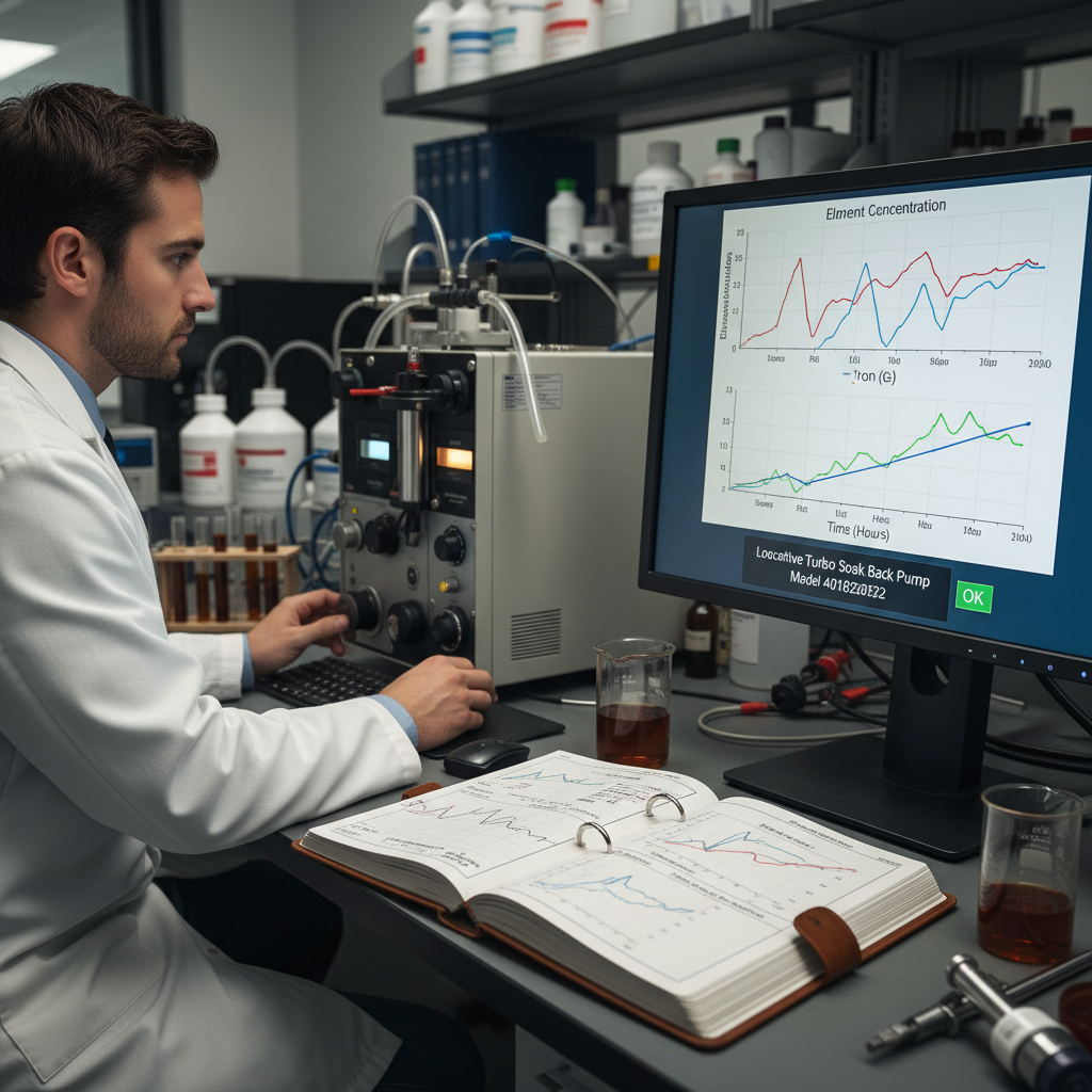
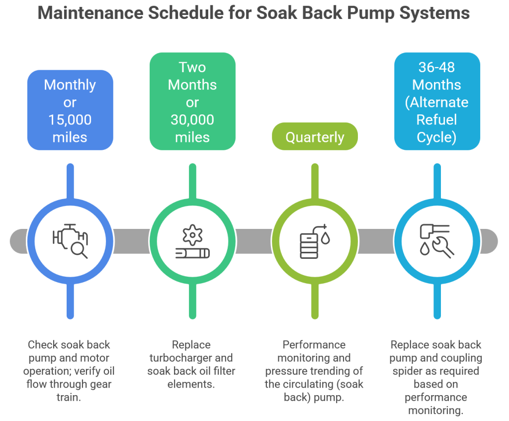
Monitoring and Pressure Testing the Soak Back System
Regular monitoring of the Turbo Soak Back Pump 40182032 system is essential. Check oil pressure and flow rates. Ensure the pump activates correctly after engine shutdown cycles. Perform pressure testing periodically. This verifies system integrity. It identifies potential leaks or blockages. Inspect the check valve testing. This ensures proper oil flow direction. Regular checks prevent system malfunctions. They guarantee continuous protection for the turbocharger. Mikura International recommends a strict monitoring schedule. This proactive approach prevents costly failures. It supports overall locomotive maintenance efforts.
Operational Control and Automatic System Integration
The Turbo Soak Back Pump 40182032 is controlled automatically. The locomotive control computer manages its activation. It engages during engine shutdown cycles. The pump operates for 30-35 minutes. This prevents thermal buildup. This action maintains turbocharger efficiency. Automated operation ensures consistent performance. It reduces manual intervention needs. This system integration is vital for engine reliability. It prevents issues like oil coking.
Pre-startup Lubrication and Post-shutdown Cooling Cycles
Activating the Turbo Soak Back Pump 40182032 before startup is critical. It ensures bearing assemblies are pre-lubricated. This significantly reduces initial wear. Post-shutdown circulation prevents heat-induced oil cracking. It stops carbon deposits from forming. This dual-phase operation extends component longevity. It protects the rotating assembly. This system prevents thermal breakdown. It is an essential part of effective turbocharger management.
Benefits of Continuous Oil Circulation Post-Shutdown
Maintaining oil flow after shutdown is crucial. Studies show it reduces thermal stress on turbocharger bearings. This prevents carbon buildup. It sustains optimal fuel efficiency over time. Continuous circulation also minimizes oil oxidation. It maintains the thermal stability threshold. This process protects the turbine wheel. It ensures the diesel prime mover operates efficiently. This proactive cooling is a cornerstone of locomotive maintenance.
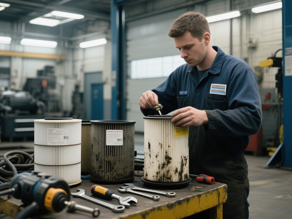
System Maintenance: Filter Replacement and Cleaning
Effective system maintenance includes regular filter replacement. The soak back filter traps contaminants. A clogged filter reduces oil flow. This compromises lubrication. Replace filters according to service intervals. Clean the system piping as needed. Inspect for any debris or sludge buildup. Proper cleaning ensures optimal oil quality. This prevents abrasive wear on bearing assemblies. This routine maintenance is vital. It supports the component longevity of the Turbo Soak Back Pump 40182032. It also protects the turbocharger’s rotating assembly.
Impact of Oil Coking on Locomotive Fuel Efficiency
Oil coking significantly impacts locomotive fuel efficiency. It leads to bearing degradation within the turbocharger. This decreases overall turbocharger efficiency. Increased fuel consumption is a direct result. Costly unplanned downtime also occurs. Preventing oil coking with the Turbo Soak Back Pump 40182032 improves engine reliability. It also enhances operational efficiency for diesel locomotive engines. Mikura International emphasizes preventative measures.
Effects of Oil Coking on Bearing and Turbocharger Life
Oil coking causes detrimental deposits. It leads to scoring and potential shaft seizure. Maintaining continuous oil circulation minimizes these damages. This extends turbocharger service life. It reduces thermal and mechanical wear. The Turbo Soak Back Pump 40182032 is crucial here. It prevents thermal breakdown and carbon deposits. This protects the turbine wheel and its bearings. Mikura International parts ensure robust performance.
Benefits of Continuous Oil Circulation Post-Shutdown
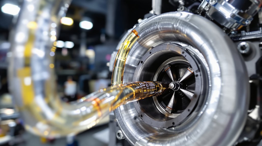
Continuous oil flow after engine shutdown is vital. It reduces thermal stress on turbo bearings. This prevents carbon buildup. Optimal fuel efficiency is sustained over time. The Turbo Soak Back Pump 40182032 facilitates this. It provides auxiliary lubrication during engine shutdown cycles. This process maintains the thermal stability threshold of the oil. It prevents oil oxidation and hydrocarbon cracking. This ensures cleaner bearing lubrication.
Materials and Design Features of Pump and Piping
The Turbo Soak Back Pump 40182032 is built for durability. It uses robust materials. These materials withstand harsh locomotive environments. The piping system is designed for high-pressure oil flow. It resists corrosion and vibration. The pump motor is engineered for continuous operation. These design features ensure reliable performance. They contribute to the component’s extended lifespan. Mikura International supplies parts meeting these high standards. Quality materials prevent premature failure. They ensure consistent auxiliary lubrication.
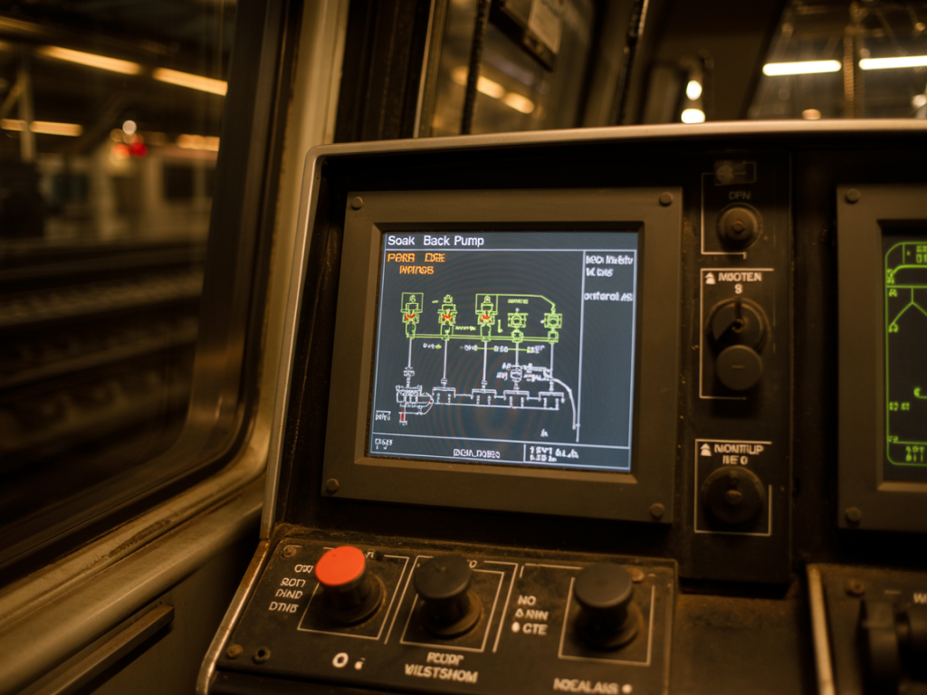
Control System Logic and Timing of Pump Activation
The locomotive control computer governs pump activation. Its logic dictates precise timing. The Turbo Soak Back Pump 40182032 engages immediately after engine shutdown. This is part of the auxiliary cooling system. It runs for a programmed duration. This duration is typically 30-35 minutes. This ensures adequate cooling. It prevents oil coking. The control system monitors engine parameters. It ensures the pump operates only when needed. This intelligent control maximizes efficiency. It minimizes energy consumption. Proper calibration of this logic is crucial. It ensures optimal protection for the turbocharger. This system is vital for Locomotive Maintenance.
Operational Control and Automatic System Integration
The Turbo Soak Back Pump 40182032 is controlled automatically. The locomotive’s computer manages this. It activates during engine shutdown cycles. This prevents thermal buildup. This is essential for maintaining turbocharger efficiency. The pump circulates oil for 30-35 minutes. This post-shutdown cooling prevents oil oxidation. It stops hydrocarbon cracking. This protects the turbine wheel and rotating assembly. It ensures component longevity. Mikura International emphasizes this critical integration.
Pre-startup Lubrication and Post-shutdown Cooling Cycles
Activating the Turbo Soak Back Pump 40182032 before startup is key. It ensures bearing assemblies are pre-lubricated. This reduces wear significantly. Similarly, post-shutdown circulation is vital. It prevents heat-induced oil cracking and oil coking. This continuous oil circulation protects the main lubrication system. It safeguards the oil gallery network. This dual-cycle approach extends turbocharger service intervals. It enhances engine reliability for Diesel Prime Mover applications.
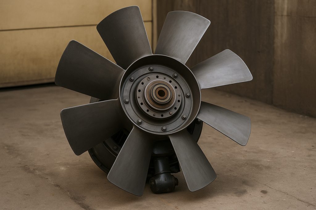
Preventing Shaft Seizure and Extending Component Longevity
Shaft seizure is a catastrophic turbocharger failure. It often results from severe oil coking. Lack of lubrication during engine shutdown cycles is a key factor. The Turbo Soak Back Pump 40182032 directly prevents this. It maintains a continuous supply of oil. This keeps the turbine wheel shaft and bearing assemblies lubricated. This action dramatically extends component longevity. It reduces the risk of expensive repairs. It ensures the rotating assembly spins freely. This contributes to overall engine reliability. Mikura International provides solutions for lasting performance.
Effects of Oil Coking on Bearing and Turbocharger Life
Oil coking causes significant damage. It leads to carbon deposits on critical surfaces. This includes bearing assemblies and the turbine wheel shaft. These deposits cause scoring and increased friction. This accelerates wear and reduces bearing lubrication effectiveness. Ultimately, coking can lead to complete shaft seizure. Maintaining continuous oil circulation minimizes these damages. It extends turbocharger management service life. This reduces thermal and mechanical wear. This is vital for diesel locomotive performance.
Benefits of Continuous Oil Circulation Post-Shutdown
Studies show maintaining oil flow after shutdown is crucial. The auxiliary lubrication provided by the Turbo Soak Back Pump 40182032 reduces thermal stress. This protects turbocharger lubrication bearings. It prevents carbon deposits from forming. This sustains optimal locomotive fuel efficiency over time. The pump circulates pressurized oil through the oil gallery network. This prevents thermal breakdown. It stops oil oxidation and hydrocarbon cracking. This ensures the oil’s thermal stability threshold is not exceeded.
Function and Role of Turbo Soak Back Pump 40182032
The Turbo Soak Back Pump 40182032 operates as an auxiliary lubrication system. It activates post-shutdown. This circulates filtered oil through the turbocharger lubrication system. This action directly reduces oil coking. By maintaining bearing lubrication, it sustains turbocharger management performance. This positively impacts locomotive fuel efficiency. It is a critical component for diesel prime mover longevity. Mikura International supplies these vital parts for EMD locomotive engines.
Pre-startup Lubrication and Post-shutdown Cooling Cycles
Activating the soak back pump before startup ensures bearing assemblies are pre-lubricated. This significantly reduces wear during initial engine operation. Similarly, post-shutdown circulation prevents heat-induced oil cracking and oil coking. This comprehensive approach maximizes component longevity. It minimizes unplanned downtime. This two-phase lubrication strategy is key to robust locomotive maintenance. It ensures optimal turbocharger management.
Ensuring Proper Bearing Clearance and Oil Oxidation Control
Maintaining correct bearing clearance is vital. Oil coking reduces this clearance. This increases friction and wear. The Turbo Soak Back Pump 40182032 prevents deposit formation. This preserves proper clearance. It also helps control oil oxidation. High temperatures accelerate oxidation. Oxidized oil forms sludge and varnish. The auxiliary cooling system reduces oil temperatures. This slows oxidation rates. This maintains oil quality. It ensures effective bearing lubrication. This dual benefit protects critical turbocharger components.
Impact of Oil Coking on Locomotive Fuel Efficiency
Oil coking severely impacts locomotive fuel efficiency. It degrades bearing assemblies. This decreases turbocharger efficiency. Increased fuel consumption results. Costly unplanned downtime also occurs. Preventing coking with the Turbo Soak Back Pump 40182032 improves reliability. It maintains optimal operational efficiency. Mikura International provides solutions for this.
Benefits of Continuous Oil Circulation Post-Shutdown
Continuous oil circulation post-shutdown is crucial. It reduces thermal stress on turbo bearings. This prevents carbon deposits. It sustains optimal fuel efficiency over time. The Turbo Soak Back Pump 40182032 ensures this circulation. This extends the life of the rotating assembly. It minimizes the risk of shaft seizure.
Effects of Oil Coking on Bearing and Turbocharger Life
Oil coking causes significant damage. It leads to deposits and scoring. Potential shaft seizure is a risk. The Turbo Soak Back Pump 40182032 minimizes these damages. It maintains continuous oil circulation. This extends turbocharger service life. It reduces thermal and mechanical wear. This protects the turbine wheel.
Pre-startup Lubrication and Post-shutdown Cooling Cycles
Pre-startup lubrication is essential. Activating the Turbo Soak Back Pump 40182032 ensures this. Bearings are pre-lubricated. This reduces wear significantly. Post-shutdown circulation prevents heat-induced oil cracking. It stops coking. This maintains the thermal stability threshold of the oil. It supports overall engine reliability.
Frequently Asked Questions
What is the primary function of the Turbo Soak Back Pump 40182032?
The Turbo Soak Back Pump 40182032 delivers auxiliary lubrication. It supplies oil to turbocharger bearings after engine shutdown. This prevents oil coking and thermal breakdown.
How does oil coking affect locomotive fuel efficiency?
Oil coking degrades turbocharger bearing assemblies. This reduces efficiency of the rotating assembly. The diesel prime mover must work harder. This increases fuel consumption and lowers engine reliability. Preventing coking enhances fuel efficiency.
For how long does the Turbo Soak Back Pump 40182032 typically operate after engine shutdown?
It operates for about 30-35 minutes after engine shutdown. This critical cycle ensures proper cooling system function. It also maintains bearing lubrication, preventing carbon deposits.
Why is pre-lubrication important for a turbocharger?
Pre-lubrication ensures bearings are oiled before engine startup. This reduces wear during initial rotation. It protects the turbine wheel and rotating assembly. This extends component longevity and minimizes unplanned downtime.
What are the critical components of the auxiliary lubrication system?
The system includes the Turbo Soak Back Pump 40182032 itself. It also uses a soak back filter and specific piping. A check valve testing ensures proper oil flow. These components prevent shaft seizure and maintain bearing clearance.
How does the Turbo Soak Back Pump 40182032 prevent thermal breakdown?
It circulates oil after the main lubrication system stops. This removes residual heat from the turbocharger. This keeps oil below its thermal stability threshold. It prevents hydrocarbon cracking and carbon deposits.
Where can I source reliable Turbo Soak Back Pump 40182032 parts?
Mikura International is a certified global supplier. We offer reliable, cost-effective replacement components. This includes the Turbo Soak Back Pump 40182032. We ensure quality for EMD locomotive engines.