
Your locomotive’s damper assembly is the hydraulic backbone that converts destructive kinetic energy into heat, directly preventing hunting oscillations and wheel lift that threaten your operations. You maintain consistent wheel-to-rail contact because calibrated piston orifices force fluid through precision passages, suppressing harmonic resonance before it escalates into derailment risk. Properly sized yaw, vertical, and lateral dampers protect your wheelsets, bearings, and bogie structure from fatigue. The right damping curve secures high-speed stability across every route condition.
What is a damper assembly in a locomotive and why is it critical for rail operations?
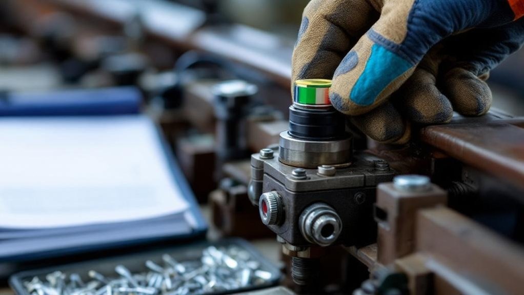
A locomotive damper assembly is a hydraulic shock absorber. It connects the bogie to the axle boxes. It dissipates energy from track-induced vibrations. This controls unwanted sway and bounce. The damper ensures stable wheel-to-rail contact. It converts kinetic energy into heat. This protects the locomotive structure. It is vital for ride quality.
The assembly uses a piston in a hydraulic cylinder. Fluid passes through precise orifices. This generates damping force. It manages yaw, pitch, and bounce motions. The damper reduces dynamic loads on bogie frames. It extends the life of wheelsets and bearings. Advanced types offer adjustable damping rates. This adapts to speed and load conditions.
Dampers are critical for operational safety. They prevent harmonic resonance and derailment risks. Poor damping causes wheel unloading and traction loss. It accelerates wear on rails and components. Maintenance costs increase without effective dampers. High-speed and heavy-haul services rely on them. Procurement must prioritize quality and reliability. Damper performance directly affects lifecycle costs.
Key Takeaways
- Hydraulic dampers prevent harmonic resonance that can escalate into derailment at speed.
- They maintain constant wheel-to-rail contact by suppressing cyclical wheel lift and bounce.
- Yaw dampers resist hunting oscillations, securing bogie alignment for high-speed stability.
- Kinetic energy is converted into heat, protecting wheelsets and bogie structures from dynamic loads.
- Proper damping calibration avoids both instability from undersized units and inefficiency from oversized ones.
Understanding the Locomotive Damper Assembly
You know a locomotive damper assembly as a hydraulic shock absorber linking the bogie to axle boxes. It evolved from simple friction snubbers into precision devices managing yaw, pitch, and bounce motions. Key terms you’ll work with include damping coefficient, orifice, and hysteretic loop.
Definition and Basic Function
A locomotive damper assembly is a hydraulic device that manages suspension movement and maintains wheel-to-rail contact. You depend on this hydraulic damping system locomotive component to absorb track-induced shocks. It converts kinetic energy into heat to control sway, bounce, and yaw effectively.
- You see a sealed piston forcing fluid through calibrated orifices inside the cylinder.
- Observe the assembly connecting bogie frames to axle boxes for controlled motion.
- Experience reduced dynamic loads protecting wheelsets, bearings, and the bogie structure.
The locomotive damper assembly dissipates vibration energy instantly. This prevents wheel unloading and ensures traction. Your damping choices directly stabilize the ride and extend component life. You secure operational safety through this proven vibration control.
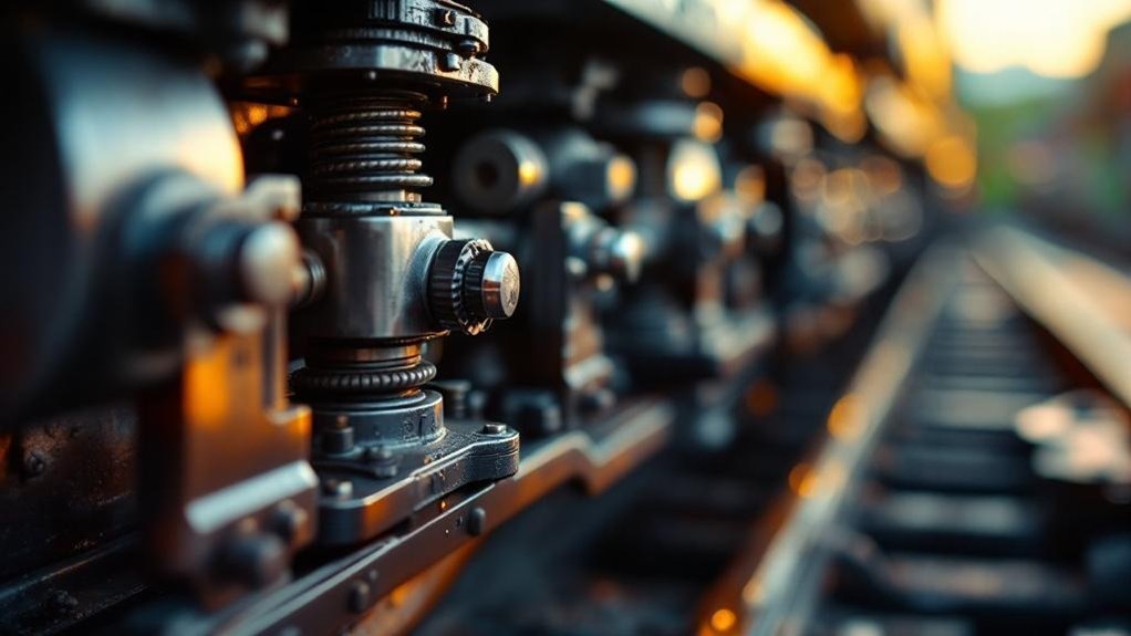
Historical Evolution
Before hydraulic systems became standard, early locomotives relied on leaf springs and simple friction snubbers to quell oscillations. You’d see engineers demand better rail vehicle vibration control as speeds increased. The 1950s introduced the hydraulic damping system locomotive, a leap from rudimentary designs. This bogie suspension damper used viscous fluid through orifices for consistent energy dissipation. By the 1980s, you’d find these dampers paired with air springs for refined dynamics. Today, you’re sourcing electronically controlled systems that adapt in real-time. These modern bogie suspension dampers adjust rates via external valves for effective rail vehicle vibration control. The progression from friction to smart hydraulics ensures you can match damping precisely to track demands and service weights.
Key Terminology
Grasping the precise language of a locomotive damper assembly lets you specify and maintain these parts properly. Key terms include:
- Damping coefficient: force per unit velocity; it quantifies damping stiffness.
- Orifice: precision piston passages that meter oil to generate force.
- Yaw damper: lateral device that controls bogie rotation, preventing hunting.
You’ll use these specs to align damper response with your locomotive’s weight and speed. Understanding them ensures you avoid undersized dampers that cause instability or oversized ones that waste energy. Correct terminology also streamlines communication with suppliers during overhauls. It helps you diagnose issues like cavitation or seal leakage by referencing exact component names. Mastering this vocabulary cuts procurement lead times and boosts fleet reliability. These three terms build your essential maintenance baseline today.
Components and Working Principle
You’ll find the hydraulic cylinder and piston at the assembly’s heart, forcing oil through valve orifices to generate damping force. You control fluid dynamics via these precision passages, instantly converting vibration energy into heat. You then integrate the damper directly with the bogie suspension to manage yaw, pitch, and bounce motions effectively.
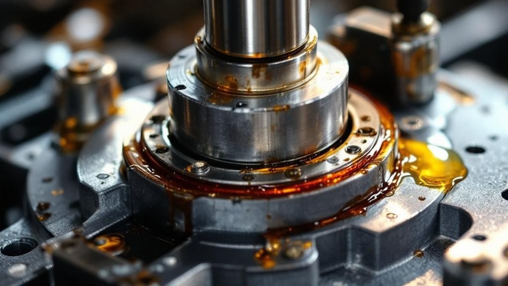
Hydraulic Cylinder and Piston
Every locomotive damper assembly relies on a precision-located piston inside a hydraulic cylinder. You see this core unit transform kinetic energy from bogie movements into heat. The piston rod forces the piston through high-grade hydraulic oil. This action pressurizes fluid within the cylinder’s chambers.
- You observe a hardened, chromed piston rod sliding through a multi-stage seal pack. This prevents fluid escape under extreme pressure.
- You find the main piston ring creates a controlled, tight gap against the cylinder’s honed inner wall.
- You see the hydraulic fluid resisting shear, generating a damping force directly proportional to the piston’s movement speed.
This resistance effectively manages yaw and bounce in your rail vehicle vibration control system. The sealed cylinder protects this process from contaminants. It ensures consistent performance for your bogie suspension damper.
Valve Orifices and Fluid Dynamics
While the piston generates movement, calibrated valve orifices dictate your damper’s precise reaction force. You manage fluid dynamics strategically. Orifice size and geometry control flow resistance. As piston speed increases, fluid shear through these passages generates velocity-dependent damping. You’ll find stacked shim valves or poppet systems covering machined ports. They deflect progressively under pressure, varying the effective orifice area. This prevents harsh lock-up during high-speed impacts. Your damper’s bleed circuit handles slow motions, ensuring compliance. You’re converting kinetic energy to heat reliably. Each orifice set targets specific vibration modes. This systematic metering secures your locomotive’s wheel-to-rail contact and bogie stability.
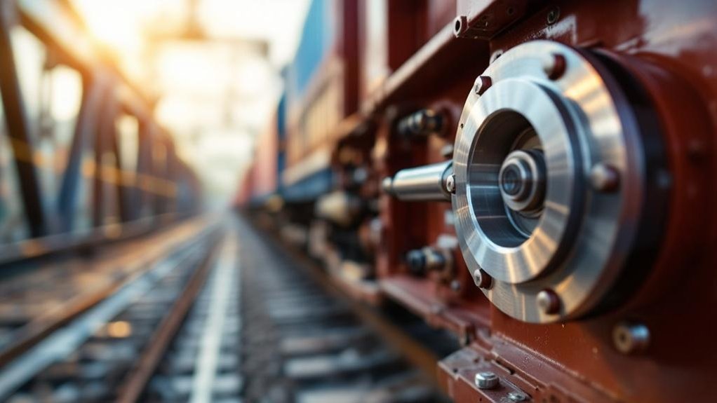
Integration with Bogie Suspension
As the damper assembly links bogie and axle boxes, it works alongside springs and linkages to control dynamic motion. You see it mounted strategically to form a cohesive suspension system. The damper doesn’t act in isolation; it’s a tuned partner in the bogie’s kinematic chain. Its precise interaction manages three critical actions:
- You dampen vertical bounce in concert with primary coil springs, preventing resonant amplification.
- Manage lateral sway by working against the axle box’s lateral stops and linkages.
- Control bogie yaw rotation through longitudinal damping, guiding stable curving.
This integrated system converts disruptive vibrational energy into heat across the entire assembly. You secure consistent wheel-to-rail contact, directly protecting the locomotive’s structure and ensuring safe, stable operation at speed.
Types of Damper Assemblies in Locomotives
You’ll start with passive hydraulic dampers—the workhorse of most fleets—where fixed orifices provide consistent, reliable force. Then, you’ll consider semi-active and active systems that adjust damping in real time, using controllers and sensors to optimize ride quality. Finally, you’ll match application-specific designs to your locomotive’s duty, whether it’s a high-speed passenger unit or a heavy-haul freight bogie.
Passive Hydraulic Dampers
Passive hydraulic dampers are the simplest and most common type found in freight locomotives. You’ll find they use a fixed-orifice design that forces oil through unchanging passages, generating consistent damping force from track-induced motion.
- You see a piston displacing hydraulic fluid through calibrated holes, converting kinetic energy into heat directly.
- Rely on this simple, robust construction which keeps manufacturing and maintenance costs low.
- You accept its fixed damping curve, as it can’t adapt to varying speeds or loads, making it a compromise for mixed conditions.
Their simplicity delivers proven reliability for heavy-haul cycles. You sacrifice adjustability, but gain a durable, low-maintenance solution where predictable performance is king.
Semi-Active and Active Dampers
Moving beyond fixed-orifice designs, semi-active and active dampers adjust damping force in real time. You’ll see electronically controlled valves quickly alter orifice sizes based on sensor feedback. This tailors resistance to track conditions and speed. You can also deploy magnetorheological (MR) fluid dampers. Here, a magnetic field instantly changes the fluid’s viscosity. That lets you modulate damping without moving parts. The system reads bogie acceleration and sends signals constantly. You gain superior yaw and bounce control, adapting to curves or irregularities instantly. These assemblies reduce wheel unloading more effectively. You’ll maximize stability while maintaining welded rail integrity. The result is dynamic performance conventional dampers can’t match. Your locomotive adjusts its ride control cleverly, not rigidly.
Application-Specific Designs
Engineers tailor locomotive damper assemblies to manage specific motion modes. You’ll find that each type targets a distinct instability for precise rail vehicle vibration control.
- Yaw dampers counteract lateral bogie rotation, stabilizing high-speed tracking and preventing hunting oscillation.
- Vertical dampers mount between the bogie and axle boxes to control bounce, absorbing impacts from rail joints or irregularities.
- Lateral dampers connect the bogie frame to the car body, restricting side-to-side sway and enhancing curve negotiation.
Selecting the correct hydraulic damping system locomotive unit demands matching the bogie suspension damper design to the service profile. This systematic approach secures wheel-to-rail contact and prolongs component life. You ensure operational safety by prioritizing this application-focused integration.
Critical Role in Rail Operations
You rely on the damper assembly for safety, as it prevents harmonic resonance that can lead to derailment. It also directly shapes ride quality by controlling bounce and sway, which protects your crew and sensitive cargo. Over time, effective damping reduces dynamic stress on bogies and wheelsets, cutting your maintenance costs and extending component life.
Safety and Derailment Prevention
While a damper assembly constantly manages routine vibrations, its most dramatic role is preventing catastrophic derailments. You rely on this hydraulic damping system to suppress dangerous oscillations before they escalate. Specifically, the bogie suspension damper counters harmonic resonance that builds at speed. It stops wheel lift, keeping your locomotive safely on the rails.
- Resonance Control: The damper dissipates energy that would otherwise amplify body and bogie oscillations, preventing a loss of stability.
- Wheel Unloading Prevention: It maintains consistent wheel-to-rail force, counteracting the cyclical lift that can precede a flange climb derailment.
- High-Speed Stability: At velocity, it resists yaw motions that cause hunting, securing the truck’s alignment under your locomotive.
Ride Quality and Passenger Comfort
Beyond the critical safety functions, a locomotive’s damper assembly directly dictates ride quality for passengers and crew. You minimize vertical and lateral vibration transmission from the bogie to the car body. A high-performance hydraulic damping system locomotive suppresses frequencies that cause discomfort and fatigue. Your bogie suspension damper controls pitch and bounce motions, ensuring a smoother journey.
You must adhere to rigorous standards like UIC 513 and ISO 2631, which define vibration exposure limits. Meeting these specifications demands rail vehicle vibration control that maintains consistent performance across speed ranges. You’ll find that precisely tuned damping transforms the in-cab environment, reducing distracting physical oscillations. Ultimately, your investment in superior damper technology pays off through enhanced passenger satisfaction and crew alertness, solidifying your locomotive’s reputation for dependable, comfortable service.
Component Longevity and Maintenance Reduction
A locomotive’s damper assembly consistently shields critical components from destructive fatigue loading. You reduce bogie frame stress and dynamic loads on wheelsets, cutting lifecycle costs. This hydraulic damping system locomotive part directly extends service intervals for bearings and axles.
- You dissipate vibration energy that otherwise accelerates metal fatigue in bogie frames.
- Stabilize wheel-to-rail contact, preventing uneven wear on wheelsets and lowering replacement frequency.
- Protect axle box bearings from impact shocks, slashing unplanned maintenance and associated downtime.
You’ll see fewer overhauls and a direct drop in material expenditures. This systematic approach converts kinetic chaos into controlled heat, keeping your heavy-haul or high-speed locomotive in service longer with proven reliability.
Procurement and Maintenance Considerations
When you select a damper, you must evaluate the damping curve against your specific locomotive’s mass and route conditions. You then analyze lifecycle costs by comparing a unit’s purchase price against its validated mean time between failures. You implement inspection best practices by using dynamometer testing to track performance degradation, not just checking for leaks.
Selection Criteria for Engineers
Engineers must evaluate precise damping force curves to match a locomotive’s mass and service speed. You’ll need specific data from manufacturers, not generic catalog values. This ensures the hydraulic damping system locomotive suppresses primary and secondary suspension movements effectively.
- Check the bogie suspension damper’s stroke length against maximum axle travel. Insufficient stroke causes bottoming out and catastrophic failure.
- Verify the operating temperature range for your climate. Fluid viscosity shifts alter damping rates, risking rail vehicle vibration control loss.
- Confirm mechanical and hydraulic compatibility with existing bogie designs. Mounting pin diameters and seal materials must match exactly.
You should then validate these specs against your route’s tonnage and curvature profile.
Reliability and Lifecycle Cost Analysis
Shifting focus from pure engineering specs, reliability and lifecycle cost analysis transforms how you procure locomotive damper assemblies. You evaluate mean time between overhauls against operational demands, demand warranty terms that cover premature hydraulic damping system locomotive failures. You calculate total cost of ownership, factoring in bogie suspension damper replacements and rail vehicle vibration control downtime. This systematic approach reveals that cheaper units often escalate lifecycle expenses. You prioritize assemblies with proven durability records, ensuring stable wheel-to-rail contact. Your procurement decisions directly reduce long-term maintenance burdens. You secure performance and safety by investing in dampers that minimize lifecycle costs.
Inspection and Overhaul Best Practices
Integrating a rigorous inspection routine into your procurement plan safeguards damper performance. You’ll systematically prevent failures before they compromise bogie suspension damper reliability.
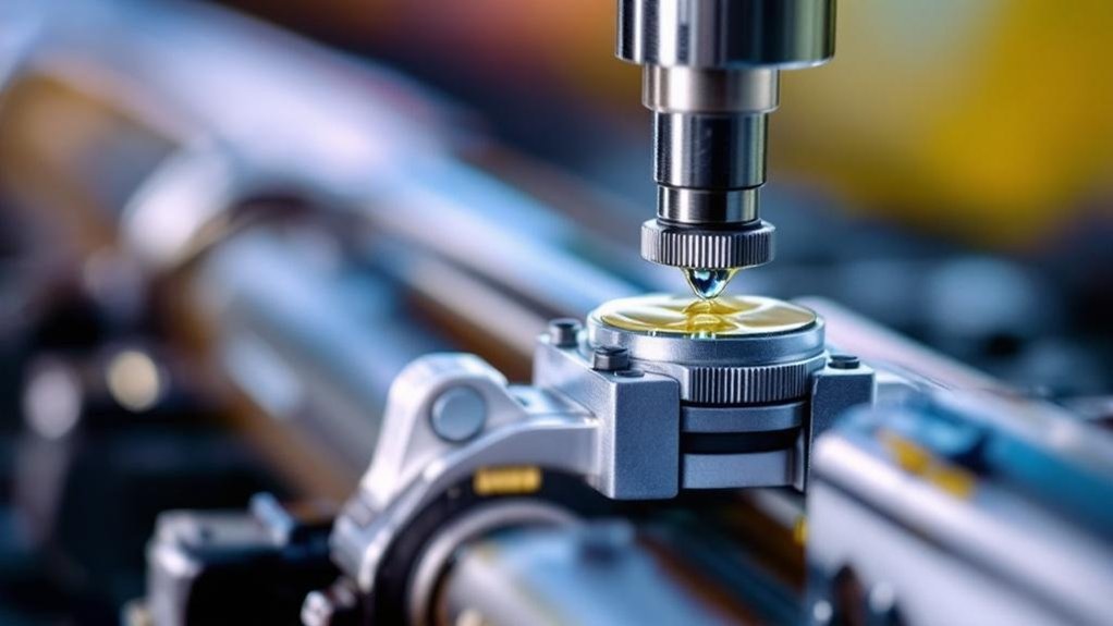
- Visual and Seal Checks: Inspect the hydraulic damping system locomotive unit for oil misting, rod scoring, or dust boot tears. You’ll spot early seal degradation fast.
- Fluid Analysis: Sample oil from the rail vehicle vibration control assembly. You’ll detect metal particulates or viscosity breakdown indicating internal wear.
- Dyno Validation: Test dampers on a dynamometer to map force-velocity curves. You’ll confirm the locomotive damper assembly meets its specified damping rates.
Base your overhaul decision on economics. If a rod is pitted or the cylinder bore is damaged, replace the unit outright to avoid unscheduled downtime.
Frequently Asked Questions
What Environmental Factors Degrade Damper Seals Fastest?
You’ll see your damper seals as a shield wall against the elements. Heat and cold launch the first assault, causing thermal cracking. Ozone and UV follow, slicing into the rubber’s molecular chains. Then dust and grit grind away at the surface like relentless sandpaper. Finally, chemical agents from cleaning solvents or hydraulic fluid leaks swell and soften the material. You must combat these attackers with diligent maintenance and robust materials.
How Do Damper Specs Differ for Mountainous Routes?
You spec dampers with stiffer valving and higher heat tolerance for mountainous routes. You need increased damping force to manage constant, severe pitch and yaw. So, you select larger oil reservoirs to dissipate intense, sustained heat from prolonged braking. You prioritize heavy-duty seals resisting extreme pressure spikes. You may specify semi-active systems to adjust rates on steep grades. This prevents fade and maintains wheel contact through tight curves.
Can Aftermarket Dampers Void Locomotive Warranties?
You risk nullifying your warranty when you install aftermarket dampers that do not meet OEM specifications. Manufacturers stipulate approved components to guarantee performance and safety. Using unverified parts shifts liability, as they can’t vouch for their interaction with the locomotive’s dynamic systems. Always verify your purchasing decisions against the warranty terms before retrofitting. Prioritize OEM or strictly equivalent-approved dampers to maintain coverage and ensure the hydraulic damping system locomotive integrity.
Is Damping Fluid Disposal Regulated by Rail Authorities?
Yes, rail authorities strictly regulate damping fluid disposal. You must follow environmental protocols when handling used hydraulic oil from your locomotive’s damping system. Your workshop collects spent fluid in designated containers for certified recycling or incineration. Never pour it into drains or soil. You work with licensed waste contractors who track disposal from cradle to grave. Your compliance avoids fines and protects the rail corridor. Always maintain disposal records for regulatory audits.
Are Rebuilt Dampers as Reliable as New Units?
You might assume a rebuilt damper cuts corners, but it can match new reliability when you demand a systematic remanufacturing process, ensuring the core components—piston rod, cylinder—undergo rigorous inspection and machining. You’re replacing all seals and valves with OEM-spec parts, not just repainting; you’re verifying performance on a calibrated dynamometer. This blueprint restores the damping curve to factory standards, giving you predictable, safe vibration control at a fraction of the cost.