Temperature shifts oil film stability, material behavior, and axial load control. Heat changes material behavior, oil film stability, and axial load control. High temperature reduces wear resistance and reliability. Low temp can slow oil flow and increase friction. Both harm locomotive efficiency and engine efficiency. The result is lost tractive effort and higher maintenance risk. Addressing temp effects protects the EMD engine and extends lifespan under heavy railroad duty.
– Monitor oil temperature, pressure, and viscosity in real time.
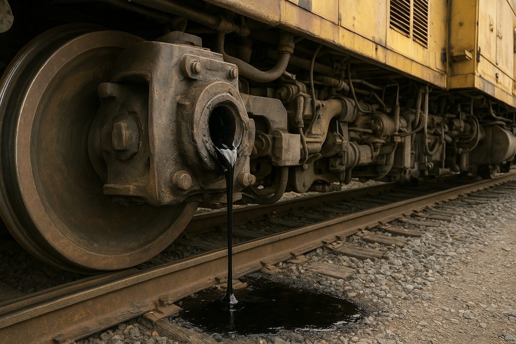
– Keep cooling systems clean, leak-free, and properly filled.
– Verify blower, radiator fan, and shutter operation.
– Use high-quality components with proven wear resistance.
– Set throttle use to minimize heat soak after heavy freight pulls.
– Inspect thrust washer axial faces during every scheduled service.
– Align main bearings to reduce side loading.
– Analyze oil for metal debris after high-temperature events.
– Simulate duty cycles to validate temperature margins.
– Calibrate temperature sensors to avoid false readings.
| Focus Area | Action |
|---|---|
| Lubrication Monitoring | Monitor oil temperature, pressure, and viscosity in real time; analyze oil for metal debris after high-temperature events. |
| Cooling System | Keep systems clean, leak-free, and filled; verify blower, radiator fan, and shutter operation. |
| Component Durability | Use high-quality components with proven wear resistance; inspect thrust washer axial faces every service. |
| Operational Practices | Set throttle use to minimize heat soak after heavy freight pulls; simulate duty cycles to validate temperature margins. |
| Instrumentation | Calibrate temperature sensors to avoid false readings; align main bearings to reduce side loading. |
As a brief guide, this article explains how temp influences an EMD thrust washer in a diesel locomotive prime mover. We detail materials, axial load paths, lubrication behavior, and controls that reduce wear. You will find practical steps to stabilize power output, protect the EMD diesel engine, and sustain performance and efficiency across US locomotives. We also share expert insights used by Mikura International, a top exporter of locomotive engine parts, to help you improve reliability.
Understanding EMD Locomotive Thrust Washers

In an EMD engine, the thrust washer manages axial loads on the crankshaft. It keeps the prime mover centered for stable torque transfer. Proper thrust control maintains valve timing, combustion stability, and tractive effort. Heat affects oil films between the bearing surfaces and the thrust washer, which can change wear rates. Managing temperature preserves locomotive efficiency and horsepower.
What is a Thrust Washer?
A thrust washer is a flat bearing element that resists axial motion of a rotating shaft. In an EMD diesel engine, it sits near main bearings to control endplay. It must survive hot oil, transient temp spikes, and start-stop thermal cycles. It works with the lube circuit to reduce wear during load changes. Kept cool and well lubricated, it preserves alignment, reduces friction, and supports consistent power.
Function of Thrust Washers in EMD Engines
Under changing throttle positions, axial loads push the crankshaft along its axis. The thrust washer maintains correct endplay to protect 645/710 geometry. This protects the 645 and 710 series geometry, keeps exhaust valve events accurate, and stabilizes piston and cylinder clearances. Stable endplay helps the generator and traction systems deliver steady tractive effort. Rising temperature thins oil films, increasing friction and reducing reliability, compromising locomotive performance and lifespan.
Common Materials Used in Thrust Washers
Typical thrust washer materials include steel-backed bronze, copper-lead, and aluminum-tin alloys. Some designs add overlays for wear resistance, conformability, and seizure resistance. Material choice must balance thermal conductivity, high-temp strength, and embeddability. EMD’s duty cycles demand alloys that handle hot oil near the exhaust passage and turbochargers zone. Proper pairing with crankshaft surfaces and oil chemistry preserves the bearing interface and supports consistent engine efficiency under load.
Impact of Temperature on Thrust Washer Performance

Temperature governs oil film behavior, material strength, and axial stability in an EMD engine. When temp rises, the thrust washer faces thinner lubrication and faster chemical oxidation of diesel engine oil. When temp falls, viscosity spikes and boundary friction grows. Both extremes threaten efficiency, horsepower, and tractive effort. To protect engine efficiency and reliability, keep systems cool, verify blower and radiator function, and monitor main bearings. Use high-quality components with strong wear resistance. Simulate duty cycles for freight operations. Balance throttle strategy to control heat soak. These actions reduce wear and extend thrust washer lifespan.
How Temperature Influences Material Properties
Elevated heat lowers yield strength and hardness, accelerating wear. Thermal expansion changes endplay and loads at the main bearings. Conductivity controls heat flow from the bearing to the crankcase, affecting oil film stability. At low temp, alloys may embrittle and lose conformability, risking scoring during cold starts. The EMD diesel environment near exhaust and turbochargers adds gradients. Matching alloy hardness to crankshaft surfaces helps reduce wear. Optimized overlays maintain seizure resistance and reliability across railway duty.
Effects of High Temperatures on Thrust Washers
High temperature thins oil and increases metal contact on the thrust washer. Oxidation forms varnish that restricts oil flow and raises friction. Softened overlays lose wear resistance, while copper-lead or aluminum-tin layers can smear under axial load. Heat from exhaust, turbochargers, and the generator region magnifies risks. Poor cooling cuts horsepower and power output as friction climbs. Blower performance and radiator airflow are vital to keep parts cool. Monitor oil pressure, endplay, and debris counts. Control throttle after heavy freight pulls to prevent heat soak. These steps protect reliability and extend lifespan.
Consequences of Low Temperatures on Performance
Low temperature thickens oil and delays full-film lubrication at startup. Boundary friction rises at the axial faces of the thrust washer, increasing wear until oil warms. Cold clearances shift as the cylinder block, piston assemblies, and main bearings contract, affecting endplay. The diesel lube circuit sees sluggish flow, reducing cooling near the thrust faces. Generator load changes can shock the interface before films form. Use preheaters where possible and short warm-up cycles. Avoid sudden throttle steps. Verify blower shutters and louvers. With controlled ramp-up, tractive effort stabilizes and locomotive reliability improves for us locomotives.
Key Factors to Consider for Optimal Performance

Control temperature, oil behavior, and axial loading for optimal thrust washer performance. Thermal gradients from exhaust and turbochargers can shift endplay and reduce wear resistance. Oil viscosity and flow must stay stable to maintain hydrodynamic films. Main bearings, piston assemblies, and the prime mover structure influence heat paths and torque stability. Operators should balance throttle, manage blower airflow, and keep the cooling loop clean. These steps protect horsepower, tractive effort, and locomotive efficiency in us locomotives during heavy freight duty and frequent load cycles.
Thermal Expansion and Compression
Uneven thermal expansion alters endplay and contact pressure. The 645 and 710 geometry can shift, changing axial loads and oil film thickness. If the crank web grows faster than the bearing carrier, contact pressure rises at the thrust faces. Compression during cooldown can pull films thin at idle. The result is higher friction and reduced engine efficiency. Map temperature rise near exhaust passages and turbochargers. Simulate hot restarts after steep grades. Maintain clearances with precise machining. Consistent thermal control preserves torque transfer and extends lifespan under railroad duty.
Lubrication and Its Role in Temperature Management
Correct viscosity is essential for hydrodynamic lift and heat removal. Lubrication manages heat by carrying energy from the thrust washer into the sump and cooler. As temp climbs, oil thins and boundary friction grows. As temp falls, flow lags and cooling weakens. Balance oil grade with expected ambient and duty cycles on the train. Verify generator load steps do not collapse films. Keep the lube cooler, blower shutters, and radiator path free of restrictions. Monitor varnish risk in diesel engine oil. Stable lubrication underpins reliability, horsepower, and power output in a diesel locomotive.
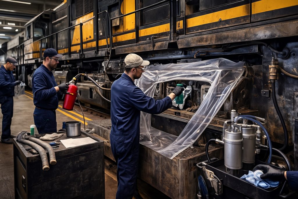
Monitoring and Maintenance Practices
Trending temperature, endplay, and debris prevents failures. Track oil temperature, pressure, and debris counts after long throttle pulls. Record endplay during every service. Inspect axial faces for scoring and overlay smear. Check blower performance, radiator airflow, and shutter response. Validate exhaust backpressure and coolant flow paths. Align main bearings and valve gear to minimize side loading. Use trending alerts to catch slow shifts in engine efficiency. When hotspots appear, simulate duty cycles to confirm margins. These disciplined steps protect locomotive efficiency, reduce wear, and sustain reliable tractive effort across railway operations.
| Focus Area | Key Actions |
|---|---|
| Fluids and Debris | Track oil temperature, pressure, and debris counts after long throttle pulls; validate coolant flow paths; validate exhaust backpressure. |
| Mechanical Alignment | Record endplay during every service; align main bearings and valve gear to minimize side loading; inspect axial faces for scoring and overlay smear. |
| Thermal and Airflow Systems | Check blower performance, radiator airflow, and shutter response; use trending alerts to catch slow shifts in engine efficiency; simulate duty cycles when hotspots appear. |
| Outcome | Protect locomotive efficiency, reduce wear, and sustain reliable tractive effort across railway operations. |
Practical Tips for EMD Locomotive Operators

Keep cooling systems clean and manage throttle to avoid heat soak. Practical actions help operators protect the thrust washer under variable temp and load. Keep cooling systems clean to maintain a cool oil supply. Sequence throttle changes to avoid heat soak. Verify turbochargers and exhaust components do not add excess heat. Watch generator loading steps near low speed. Align lubrication intervals with freight schedules. Use high-quality components for consistent wear resistance. When questions arise, Mikura International can advise on material upgrades and fitment. These measures stabilize torque delivery, preserve horsepower, and extend the prime mover’s lifespan in demanding EMD diesel service.
Regular Temperature Monitoring Techniques
Use calibrated sensors and trend data against load and throttle. Use calibrated sensors at oil galleries near the thrust washer and main bearings. Add infrared scans along the crankcase and exhaust side during heavy pulls. Log temperature against throttle position, generator load, and AC motor traction events. Compare warm-up curves after overnight cold soak on the railway. Set alarms for fast temperature rise that outpaces pressure. Trend coolant inlet and outlet deltas to detect fouling. Correlate debris in filters with spikes. These techniques improve reliability by catching early faults, protecting tractive effort and engine efficiency in US locomotives.
| Action | Purpose/Metric |
|---|---|
| Use calibrated sensors at oil galleries near the thrust washer and main bearings | Accurate temperature and pressure readings at critical bearings |
| Add infrared scans along the crankcase and exhaust side during heavy pulls | Detect localized hot spots under high load |
| Log temperature vs. throttle position, generator load, and AC motor traction events | Correlate thermal behavior with operating conditions |
| Compare warm-up curves after overnight cold soak on the railway | Identify deviations in heat-up profiles |
| Set alarms for fast temperature rise that outpaces pressure | Early warning of lubrication or cooling issues |
| Trend coolant inlet/outlet deltas | Detect fouling in the cooling circuit |
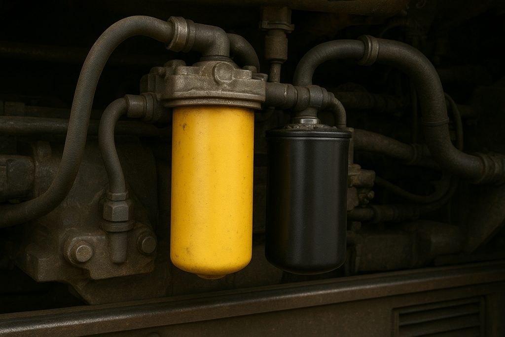
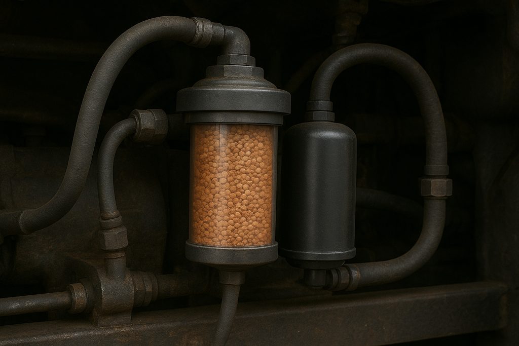
| Correlate debris in filters with spikes | Link contamination events to operational anomalies |
Best Practices for Thrust Washer Maintenance
Consistent endplay measurement and clean oil galleries are critical. Measure endplay with the same procedure each service to track axial drift. Inspect overlay condition and contact patterns on both thrust faces. Replace seals that admit dust, which accelerates wear under temp stress. Verify oil jets and galleries are clean and centered. Check valve train timing and piston-to-cylinder clearances that influence axial loading. Refresh oil before oxidation raises varnish and friction. After overheating events, sample oil and inspect for copper or tin. Follow torque specs on caps to maintain geometry. These practices reduce wear and sustain performance and efficiency in the EMD engine.
Upgrading Materials for Enhanced Performance
Choose alloys and overlays optimized for high-temperature duty. Consider steel-backed bronze with optimized overlays for high-temp reliability in a diesel locomotive prime mover. Enhanced aluminum-tin or copper-lead systems with solid lubricants can improve seizure resistance. Select alloys with better thermal conductivity to keep faces cool under freight loads. Match surface finish to the crank thrust collar for stable films. Validate upgrades with lab rigs and simulate duty cycles on the locomotive. Mikura International supplies high-quality components tailored to 645 and 710 applications. Proper material pairing preserves torque, power output, and locomotive efficiency while extending lifespan under railroad conditions.
Expert Insights on Thrust Washer Efficiency

Stable oil films, controlled temperature, and precise alignment drive efficiency. Thrust washer efficiency in an EMD engine hinges on stable oil films, controlled temp, and accurate axial alignment. Expert practice focuses on matching bearing materials to the prime mover’s thermal map, especially near exhaust and turbochargers. Engineers map heat flow from the cylinder block to main bearings to keep the thrust washer cool. They tune oil viscosity for freight duty, throttle transitions, and generator load steps. They validate endplay under simulated gradients. This protects tractive effort, torque, and locomotive efficiency in us locomotives while extending lifespan and reliability.
Industry Standards for EMD Components
Standards define endplay, surface finish, and hardness to stabilize films. Industry standards specify dimensional tolerances, surface finish, and hardness for thrust washer and main bearings in the EMD engine. They define endplay ranges for 645 and 710 families, oil gallery cleanliness, and overlay adhesion. Standards require consistent axial face flatness to stabilize films under diesel locomotive loads. Cool oil delivery and varnish control are emphasized. Inspection protocols mandate repeatable measurements and traceable gauges. Documentation links generator loading, blower airflow, and coolant temperatures to acceptance limits. These controls reduce wear, preserve horsepower, and sustain engine efficiency and power output on the railway.
Case Studies on Temperature Effects
Fixing cooling airflow and oil grade restored reliability in real fleets. A freight loco experienced rising debris counts after mountain grades. Data showed temp spikes near the thrust washer as blower shutters stuck. The oil thinned, and axial wear increased. Cleaning the shutters and adjusting throttle steps restored tractive effort and reliability. Another EMD diesel case saw cold starts on a northern railway. Viscosity was too high, delaying films at the axial faces. A revised oil grade and short warm-up stabilized torque. A third case used simulated duty cycles. It proved overlay upgrades improved wear resistance under exhaust-side heat, enhancing performance and efficiency.
Future Trends in Thrust Washer Technology
Advanced overlays, micro-textures, and embedded sensing will boost reliability. Future thrust washer designs will blend steel-backed bronze with advanced solid lubricants to reduce wear under variable temp. Micro-textured axial faces will hold oil and cool hotspots. Coatings with higher seizure resistance will protect during cold starts and sudden throttle changes. Embedded sensors may monitor temp, film status, and axial load in real time. Models will simulate railway gradients and ac motor traction events to predict risk. Optimized oil chemistries will resist oxidation near turbochargers. Together, these trends boost locomotive efficiency, horsepower stability, and lifespan in demanding diesel locomotive service.
Conclusion
Effective temperature control stabilizes oil films, torque transfer, and engine efficiency. Effective temperature control protects the thrust washer, the generator coupling, and the prime mover’s axial balance. It keeps oil films stable across main bearings and axial faces. This secures torque transfer, tractive effort, and engine efficiency in an EMD diesel. Operators should monitor coolant, blower performance, and exhaust-side hotspots. They should select high-quality components and match oil to duty. Validated maintenance and simulated freight profiles mitigate risk. The result is consistent power output, reliable combustion, and longer lifespan for us locomotives across harsh railway environments.
Recap of Temperature Impact on Performance
High temp thins oil; low temp raises viscosity-both shift axial loads and cut efficiency. High temp thins oil, weakens overlays, and raises friction at the thrust washer. Low temp increases viscosity and delays hydrodynamic lift. Both shift axial loads and reduce locomotive efficiency. Exhaust heat and turbochargers intensify gradients. Poor cooling harms horsepower and torque stability. Proper oil grade, clean radiators, and working shutters keep components cool. Endplay checks and debris trending reduce wear. When operators control throttle steps and validate generator load transitions, tractive effort stays steady. These actions preserve performance and efficiency in the EMD engine across 645 and 710 platforms.
Final Thoughts on EMD Thrust Washers
Control temperature, confirm axial geometry, and maintain clean lubrication. Precision in materials, oil selection, and alignment defines thrust washer success in a diesel locomotive. Control temp, confirm axial geometry, and maintain clean lubrication. Use overlays with proven wear resistance and conformability. Map thermal paths near the exhaust valve region to prevent local hotspots. Simulate steep grades and hot restarts to validate margins. When maintained well, the thrust washer protects the prime mover, generator, and traction motor systems. It safeguards locomotive reliability, power output, and torque delivery under heavy freight duty on the railroad and the wider railway network.
How Mikura International Supports Engine Parts Excellence
Mikura International supplies optimized thrust washer solutions and guidance. Mikura International provides high-quality components for EMD engines, including thrust washer solutions tailored to 645 and 710 duty. We advise on alloys, overlays, and surface finishes to keep axial faces cool and reduce wear. Our experts help match oil chemistry and endplay targets to freight cycles. We simulate gradients and load steps to confirm performance. We support inspection protocols, debris trending, and geometry control. With our guidance, operators improve engine efficiency, horsepower stability, and tractive effort. That strengthens reliability and extends lifespan across us locomotives and global railway fleets.