
The turbocharger represents one of the most critical components in any GE 7FDL locomotive engine. This sophisticated system pressurizes intake air, dramatically improving engine efficiency and power output. Yet many fleet operators and maintenance technicians operate without a clear understanding of the GE 7FDL turbocharger maintenance schedule—a gap that can lead to unexpected downtime, costly repairs, and reduced locomotive performance.
Proper turbocharger maintenance isn’t optional; it’s essential for extending engine life, maintaining fuel efficiency, and ensuring reliable operation across all operational conditions. The GE 7FDL engine, with its proven track record in heavy-haul and passenger service, demands a systematic approach to turbocharger care. This comprehensive guide walks you through everything you need to know about maintaining your GE 7FDL turbocharger, from basic service intervals to advanced diagnostic procedures that identify problems before they become catastrophic failures.
Understanding the GE 7FDL Turbocharger System
Before diving into specific maintenance procedures, it’s important to understand how the turbocharger functions within the larger GE 7FDL diesel engine ecosystem. The turbocharger comprises several interconnected components working in precise harmony. The turbocharger compressor wheel draws ambient air and pressurizes it before sending it to the engine’s combustion chambers. Meanwhile, the turbine wheel, driven by exhaust gases, powers the compressor section. These components rotate at extraordinary speeds—often exceeding 20,000 RPM—making precision engineering and meticulous maintenance absolutely critical.
The intercooler and turbocharger system works together to manage intake air temperature and pressure. As compressed air heats during compression, the intercooler cools this air before it enters the engine, improving combustion efficiency and reducing thermal stress on cylinder components. Understanding these interactions helps explain why maintenance addressing the complete turbocharger system—not just individual components—delivers superior results.
Establishing Your GE 7FDL Turbocharger Maintenance Schedule
The foundation of effective turbocharger care rests on understanding manufacturer-recommended maintenance intervals. GE specifies that turbocharger inspection and service occurs at regular intervals based on operating hours. While exact intervals vary depending on specific locomotive configuration and operational duty cycle, most GE 7FDL engines require turbocharger evaluation every 30,000 to 60,000 operating miles. This scheduling prevents small issues from developing into major problems requiring complete turbocharger replacement.
However, standard maintenance schedules represent minimums, not maximums. Operating conditions significantly influence actual maintenance frequency. Locomotives operating in high-dust environments, such as desert rail corridors or grain-transport routes, accumulate turbocharger deposits more rapidly than those in moderate-climate applications. Similarly, locomotives operating at consistently high power settings experience greater turbocharger stress than those with varied duty cycles. Fleet managers should adjust maintenance schedules upward when these aggravating factors exist, conducting inspections more frequently to catch problems early.
Turbocharger Oil Change Frequency and Lubrication
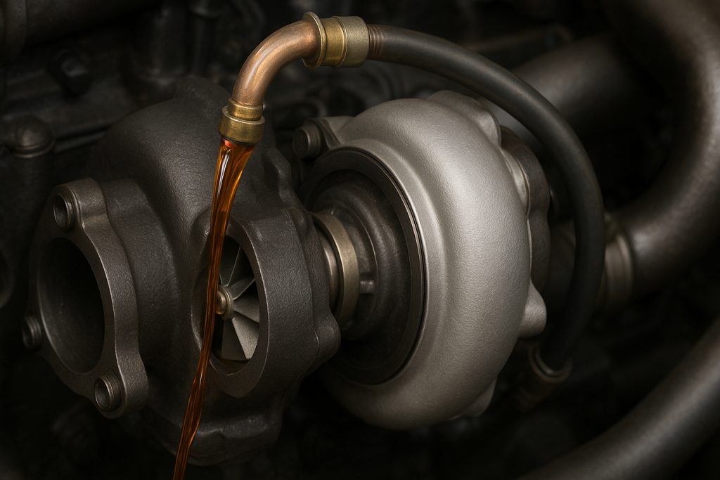
Proper turbocharger bearing lubrication represents perhaps the single most important maintenance factor. Turbocharger bearings operate under extreme pressure and temperature conditions, relying on engine oil for both lubrication and cooling. Oil flowing through turbocharger bearings carries away heat generated by high-speed rotation while maintaining the thin film that prevents metal-to-metal contact. Degraded or insufficient oil leads to accelerated bearing wear, loss of boost pressure, and eventual bearing failure.
Most GE 7FDL applications require engine oil changes at intervals aligned with overall engine maintenance—typically every 1,000 to 1,500 operating hours depending on duty cycle and oil quality. Since turbocharger bearing lubrication depends on engine oil quality, changing engine oil on schedule directly protects turbocharger integrity. When determining appropriate oil change intervals, consider using synthetic or high-quality multi-grade diesel oils specifically formulated for turbocharged applications. These premium oils maintain better viscosity stability at turbocharger operating temperatures, providing superior bearing protection compared to conventional mineral oils.
Additionally, many experienced locomotive maintenance supervisors implement supplemental turbocharger flushing procedures during major engine overhauls. This procedure involves circulating fresh, clean oil through turbocharger bearing passages to remove accumulated carbon deposits and varnish. This maintenance step, typically performed every 100,000 miles or during major scheduled maintenance intervals, significantly extends turbocharger service life.
Turbocharger Bearing Lubrication System Inspection
Beyond oil changes, inspecting the complete turbocharger bearing lubrication system ensures optimal performance. Technicians should verify that oil supply lines connecting the engine to turbocharger bearings remain clear of obstructions and properly routed without kinks or crush points. Oil return lines must slope downward at proper angles to ensure gravity-assisted drainage; improper line routing can cause oil backing up into turbocharger bearing passages, leading to pressure-fed bearing damage.
Examine oil supply passages within the turbocharger housing for carbon buildup or sludge accumulation. When carbon deposits restrict oil flow to bearing surfaces, bearing temperatures rise rapidly despite adequate oil volume. This thermal stress accelerates bearing wear, leading to increased turbocharger blade clearances and eventual blade rub against turbocharger housing. If inspection reveals significant carbon accumulation, the turbocharger requires professional cleaning or replacement, depending on damage severity.
Boost Pressure Sensor Maintenance and Performance Monitoring
The GE 7FDL boost pressure sensor continuously monitors turbocharger output pressure, sending signals to the engine control system to optimize fuel injection and air/fuel ratios. A functioning boost pressure sensor is essential for maintaining emissions compliance, engine efficiency, and performance consistency. Maintenance procedures should include regular verification that boost pressure readings remain within manufacturer specifications across the full operating range.
Boost pressure that falls below normal specifications indicates potential turbocharger issues—worn compressor blades, seal degradation, or bearing wear allowing excessive blade clearances. Conversely, boost pressure exceeding specifications suggests possible waste gate valve malfunction preventing proper turbocharger modulation. When boost pressure readings deviate from specifications, diagnostic procedures must identify root causes before operational degradation accelerates turbocharger deterioration.
Waste Gate Valve Inspection Procedures
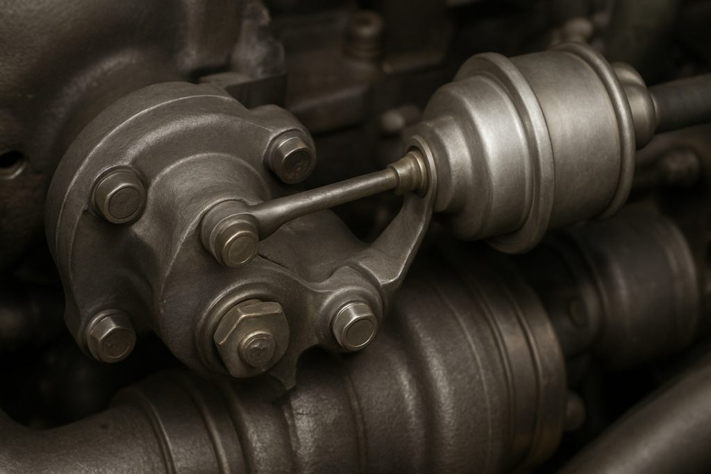
The waste gate valve controls turbocharger boost by bypassing excess exhaust gas away from the turbine section when boost pressure exceeds target levels. If the waste gate becomes stuck in the closed position, uncontrolled turbocharger acceleration drives excessive boost pressure, potentially causing compressor surge and blade damage. Conversely, waste gate sticking in the open position prevents adequate boost development, reducing engine power and efficiency.
Regular waste gate inspection involves checking valve actuation response and verifying proper spring tension. Technicians should manually actuate the waste gate linkage while listening for smooth, consistent movement and observing that the valve returns properly to seated position when actuating force is released. If waste gate movement feels stiff, rough, or irregular, the valve requires cleaning or replacement before operational cycling further damages the mechanism.
GE 7FDL Engine Turbocharger Heat Management
Turbocharger heat management directly impacts component longevity and system reliability. Exhaust manifolds and turbine housing operate at temperatures exceeding 1,000 degrees Fahrenheit, creating intense thermal stress on turbocharger materials. Proper maintenance ensures heat management systems function effectively. Technicians should verify that turbocharger heat shields remain intact and properly positioned, directing radiant heat away from sensitive engine and mounting components. Damaged or missing heat shields allow excessive temperature transfer to engine structure, potentially degrading adjacent components and creating fire hazards.
Additionally, inspect cooling lines that circulate coolant through some turbocharger housings. These lines prevent turbocharger case temperature from rising excessively, protecting seals and bearing housings from thermal degradation. Ensure cooling line connections remain tight and free from leaks, and verify that coolant flows properly through turbocharger cooling passages when the engine operates.
Compressor Wheel Cleaning and Inspection
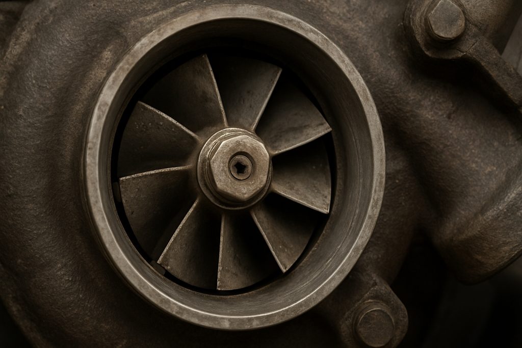
The compressor wheel draws air from the locomotive’s surroundings and pressurizes it for combustion. Over time, deposits accumulate on compressor blade surfaces, reducing air compression efficiency and increasing turbocharger work demand. This degradation manifests as reduced engine power, increased fuel consumption, and elevated turbocharger operating temperatures. Professional turbocharger cleaning services remove these deposits, restoring compression efficiency and reducing thermal stress on turbocharger components.
Technicians should inspect compressor wheel blade surfaces for corrosion, erosion, or metal fatigue cracking. Small surface erosion from dust particles is normal in diesel engine service; however, significant blade erosion or cracking indicates turbocharger replacement is preferable to attempting repair. Blade failure can produce loose fragments entering combustion chambers or engine exhaust systems, potentially causing secondary damage to cylinders, pistons, or exhaust systems.
Exhaust Manifold Maintenance and Turbocharger System Integration
The turbocharger exhaust manifold directs hot exhaust gases to the turbine section. Cracks in exhaust manifolds allow exhaust gas escape into engine compartments, reducing energy available for turbocharger operation and creating safety hazards from high-temperature gas exposure. Regularly inspect exhaust manifolds for visible cracks, loose connections, or excessive scaling. If cracks appear early in the manifold’s service life, investigate whether engine operating conditions or maintenance deficiencies are contributing factors.
Ensure all exhaust manifold fasteners remain tight, as vibration and thermal cycling can loosen connections over time. Loose manifold sections allow exhaust gas bypass, reducing turbocharger efficiency and preventing normal boost development. Additionally, verify that exhaust system isolation components—gaskets, seals, and mounting isolators—maintain proper separation between hot exhaust components and adjacent engine structures.
Advanced Diagnostic Techniques for Turbocharger Assessment
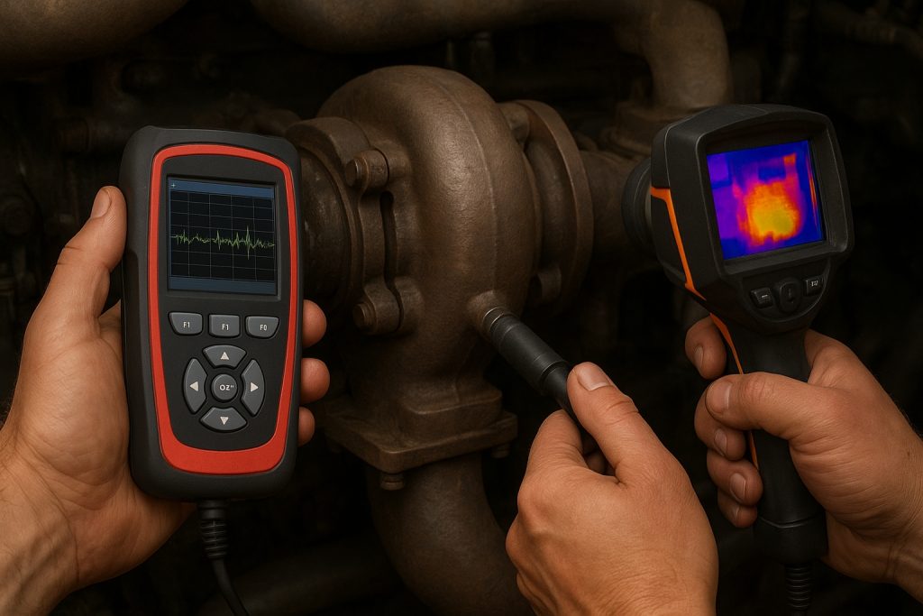
Modern locomotive maintenance increasingly incorporates advanced diagnostics to assess turbocharger condition without complete disassembly. Spool-up time measurements indicate how quickly the turbocharger accelerates from idle to full boost—rapid acceleration suggests healthy turbocharger condition, while sluggish acceleration indicates potential bearing wear, blade damage, or seal degradation. Comparing spool-up acceleration to historical baseline measurements from previous service intervals reveals trends indicating developing problems.
Vibration analysis can detect turbocharger bearing issues long before traditional inspection methods identify problems. Elevated vibration signature frequencies associated with rolling element bearing operation suggest bearing wear patterns requiring professional assessment. Similarly, infrared thermography reveals hot spots indicating restricted oil flow or excessive friction within turbocharger bearings—conditions requiring intervention before catastrophic failure occurs.
Conclusion and Recommended Maintenance Best Practices
Maintaining your GE 7FDL turbocharger maintenance schedule demands commitment to systematic procedures, attention to detail, and genuine understanding of how turbocharger components interact within the larger engine system. By implementing the guidance provided in this comprehensive guide—following manufacturer service intervals, prioritizing oil quality and turbocharger bearing lubrication, monitoring boost pressure performance, and conducting regular visual inspections—fleet operators and maintenance professionals ensure their GE 7FDL locomotives perform reliably while minimizing unexpected downtime and expensive emergency repairs.
The investment in preventive turbocharger maintenance delivers remarkable returns through extended component lifespan, improved fuel efficiency, consistent engine performance, and reduced total lifecycle costs. Whether you manage a single locomotive or an extensive fleet, implementing these proven maintenance procedures protects your valuable equipment while supporting safe, efficient transportation operations.
Ready to optimize your GE 7FDL turbocharger performance? Download our comprehensive maintenance checklist or contact our specialists today for personalized guidance on implementing these proven procedures for your specific locomotive application. Our team of experienced technicians stands ready to provide expert support, genuine OEM-quality components, and the technical assistance your fleet operations demand.
Get Expert Turbocharger Support Now!
You can also read: GE Locomotive Parts: Unveiling Quality Components for Optimal Performance