Comparing ALCO 251+ Cylinder Head Variants

Comparing ALCO 251+ Cylinder Head Variants

Introduction

The ALCO 251+ diesel engine series is widely used in various industries, including locomotives, marine vessels, and power generation. The cylinder head is a vital component of this engine, and understanding the different variants is crucial for maintenance and repairs. This article explores the various ALCO 251+ cylinder head variants and highlights their importance in ensuring optimal engine performance.

Overview of ALCO 251+ Cylinder Head Variants

The ALCO 251+ series offers several cylinder head variants, each designed for specific applications and performance requirements. These variants include:

  1. 18:1 Compression Ratio: This variant is commonly used in marine applications. With a lower compression ratio, it provides reliable operation and increased fuel efficiency for long-haul journeys.
  2. 14:1 Compression Ratio: Used in locomotives and stationary power generation, this variant offers higher power output and enhanced performance, making it suitable for demanding applications.
  3. 16:1 Compression Ratio: This variant strikes a balance between the 18:1 and 14:1 compression ratios. It is often utilized in both marine and locomotive applications, providing a combination of power and fuel efficiency.
  4. Turbocharged Variant: Turbocharging is a common practice to increase engine power. ALCO offers turbocharged cylinder head variants for applications that require higher horsepower and improved performance.

Importance of understanding different variants for maintenance and repairs

Knowledge of the various ALCO 251+ cylinder head variants is crucial for maintenance and repair purposes. Here’s why:

  1. Replacement Compatibility: When a cylinder head needs replacement, it is essential to ensure compatibility with the specific variant installed in the engine. Choosing the wrong variant can lead to performance issues and engine damage.
  2. Performance Optimization: Understanding the different compression ratios and turbocharged options allows technicians to select the most suitable variant based on the application requirements. This ensures optimal engine performance and efficiency.
  3. Troubleshooting: In the event of performance issues or repairs, knowing the specific variant enables technicians to troubleshoot problems more effectively. They can identify potential issues related to compression ratios, turbocharging, or other variant-specific features.
  4. Spare Parts Inventory: Having a clear understanding of the various cylinder head variants helps in maintaining an appropriate inventory of spare parts. This streamlines the maintenance process and reduces downtime.

In conclusion, the ALCO 251+ cylinder head variants play a crucial role in ensuring optimal engine performance for diverse applications. Understanding the different compression ratios and turbocharged options allows for effective maintenance, troubleshooting, and spare parts management. By selecting the appropriate variant and conducting regular maintenance, engine operators can maximize the lifespan and efficiency of their ALCO 251+ diesel engines.

ALCO 251+ Cylinder Head Variants

ALCO 251+ Cylinder Head Variant A

Specifications and features

The ALCO 251+ Cylinder Head Variant A is a key component of the ALCO 251+ diesel engine series. It is designed to deliver optimal performance and reliability in various industrial applications. This cylinder head variant is known for its robust construction, durability, and efficiency.

The specifications and features of the ALCO 251+ Cylinder Head Variant A include:

  1. Design: The cylinder head is designed to withstand high temperatures and pressures, ensuring efficient combustion and power delivery.
  2. Material: It is made from high-quality cast iron or aluminum alloy, providing strength and resistance to wear and tear.
  3. Cooling System: The cylinder head is equipped with an efficient cooling system that helps maintain optimal engine temperature, preventing overheating and maximizing performance.
  4. Combustion Chamber: The combustion chamber is designed to promote efficient fuel combustion, resulting in improved fuel efficiency and reduced emissions.
  5. Valve System: The cylinder head features a valve system with carefully engineered valve ports and seats, optimizing airflow and enhancing engine performance.

Performance comparisons

The ALCO 251+ Cylinder Head Variant A offers several advantages over its counterparts. It has been widely acknowledged for its superior performance and reliability in the industry. Here are some key performance comparisons:

  1. Power Output: The ALCO 251+ Cylinder Head Variant A delivers impressive power output, allowing for high torque and improved acceleration. This enables it to handle heavy workloads efficiently.
  2. Fuel Efficiency: With its efficient combustion chamber design and optimized valve system, this cylinder head variant ensures excellent fuel efficiency. This can result in significant cost savings over the long term.
  3. Durability: The ALCO 251+ Cylinder Head Variant A is known for its durability and longevity. It is carefully engineered to withstand the demands of industrial applications, providing reliable operation even under harsh conditions.
  4. Maintenance: The cylinder head variant requires regular maintenance and inspection to ensure optimal performance. However, its robust construction and design minimize the need for frequent repairs or replacements.
  5. Compatibility: The ALCO 251+ Cylinder Head Variant A is compatible with the ALCO 251+ diesel engine series, making it a versatile choice for a wide range of applications.

In conclusion, the ALCO 251+ Cylinder Head Variant A offers exceptional specifications, features, and performance benefits. Its durable construction, efficient cooling system, and optimized valve system contribute to its reliability and efficiency. Whether used in locomotives, power generation, or marine applications, this cylinder head variant is a trusted choice for many industries.

ALCO 251+ Cylinder Head Variant B

Specifications and features

The ALCO 251+ Cylinder Head Variant B is a high-performance component designed for ALCO 251+ diesel engines. It offers several unique specifications and features that make it an excellent choice for businesses in need of reliable and efficient power generation.

One notable feature of the ALCO 251+ Cylinder Head Variant B is its enhanced cooling capabilities. This variant is equipped with improved cooling channels, which allow for better heat dissipation. As a result, the engine can operate at optimal temperatures, leading to improved performance and longevity.

Additionally, the cylinder head variant B is engineered with a refined combustion chamber design. This design promotes better air/fuel mixing, resulting in improved fuel efficiency and reduced emissions. Businesses that prioritize environmental sustainability can benefit from this feature by lowering their carbon footprint.

Furthermore, the ALCO 251+ Cylinder Head Variant B is constructed with high-quality materials to ensure durability and reliability. The cylinder head is made from a robust alloy, which can withstand the demanding operating conditions of industrial engines. This durability translates to reduced maintenance costs and longer service life.

Performance comparisons

In terms of performance, the ALCO 251+ Cylinder Head Variant B offers notable advantages over other variants. Comparative studies have shown that this variant provides increased power output, making it suitable for applications that require high levels of performance.

The improved cooling capabilities of the cylinder head variant B also contribute to superior performance. By preventing overheating and maintaining optimal temperatures, the engine can operate consistently at its peak power output. This is especially crucial for applications that demand sustained power over long periods.

Additionally, the enhanced combustion chamber design of the variant B ensures efficient fuel combustion. This leads to better fuel economy, saving businesses on fuel costs and reducing their overall operating expenses.

The ALCO 251+ Cylinder Head Variant B has been tested and proven to deliver reliable performance in various industries, including power generation, marine, and rail. Its robust construction and advanced features make it a popular choice among businesses looking for a dependable and efficient engine component.

In conclusion, the ALCO 251+ Cylinder Head Variant B offers several advantages for businesses seeking enhanced performance and reliability. With its superior cooling capabilities, improved combustion chamber design, and durable construction, this variant can significantly enhance the efficiency and lifespan of ALCO 251+ diesel engines.

ALCO 251+ Cylinder Head Variant C

Specifications and features

The ALCO 251+ Cylinder Head Variant C is a popular choice for locomotives and power generation applications. It is known for its durability, efficiency, and performance. Here are some key specifications and features of the Variant C:

  • Cylinder arrangement: Inline, 4-stroke cycle
  • Cylinder head material: High-strength cast iron
  • Fuel injection system: Direct injection
  • Turbocharging: Single-stage turbocharger
  • Cooling system: Water-cooled
  • Compression ratio: 14:1
  • Combustion chamber design: Swirl chamber
  • Valve arrangement: Overhead, dual camshaft

These specifications contribute to the overall performance and reliability of the engine. The durable cast iron cylinder head ensures long-lasting operation, while the direct fuel injection system provides efficient fuel consumption. The single-stage turbocharger enhances power output, and the water-cooling system helps maintain optimal operating temperatures. The swirling combustion chamber design promotes efficient fuel combustion, resulting in improved fuel efficiency and reduced emissions. The overhead valve arrangement with dual camshafts ensures precise valve timing and enhances engine performance.

Performance comparisons

When comparing the performance of the ALCO 251+ Cylinder Head Variant C with other variants in the ALCO 251+ series, several factors come into play. These factors include power output, fuel efficiency, reliability, and emissions. Here is a comparison of the Variant C with its counterparts:

  • Power output: The Variant C offers a competitive power output, delivering a reliable and consistent performance across a wide range of applications.
  • Fuel efficiency: With its efficient fuel injection system and combustion design, the Variant C exhibits excellent fuel efficiency, minimizing operational costs without compromising performance.
  • Reliability: The Variant C is known for its durability and long service life. It is designed to withstand demanding operating conditions and requires minimal maintenance, ensuring high availability and reduced downtime.
  • Emissions: The ALCO 251+ Cylinder Head Variant C meets stringent emission regulations, contributing to environmental sustainability and compliance with emissions standards.

It is important to note that the choice of the cylinder head variant ultimately depends on the specific application requirements and operational needs. Each variant in the ALCO 251+ series offers unique advantages and may be more suitable for different applications.

In conclusion, the ALCO 251+ Cylinder Head Variant C stands out with its durability, efficiency, and performance. With its robust specifications and features, it offers reliable power output, fuel efficiency, and low emissions. Whether it’s for locomotives or power generation, the Variant C remains a popular choice in the industry.

ALCO 251+ Cylinder Head Variant D

Specifications and features

The ALCO 251+ Cylinder Head Variant D is a popular choice among locomotive operators for its reliable performance and robust construction. Here are some key specifications and features of this variant:

  1. Material: The cylinder head is made from high-quality cast iron, which ensures durability and longevity even under heavy operating conditions.
  2. Design: The design of the cylinder head is optimized for maximum combustion efficiency, resulting in better fuel economy and reduced emissions.
  3. Valve arrangement: This variant features a four-valve-per-cylinder arrangement, which allows for better air intake and exhaust flow, resulting in improved engine performance.
  4. Easy maintenance: The cylinder head design allows for easy access to valves and other components, making maintenance and repairs more convenient.
  5. Standardized parts: The ALCO 251+ Cylinder Head Variant D uses standardized parts, which means that replacements and spare parts are readily available, reducing downtime and maintenance costs.

Performance comparisons

When comparing the performance of the ALCO 251+ Cylinder Head Variant D with other variants, several factors come into play. Here are some performance comparisons to consider:

  1. Power output: The ALCO 251+ Cylinder Head Variant D offers excellent power output, making it suitable for various applications, including heavy haulage and freight transportation.
  2. Fuel efficiency: Due to its optimized design, this variant delivers better fuel efficiency, reducing operating costs for locomotive operators.
  3. Reliability: The ALCO 251+ Cylinder Head Variant D has a reputation for reliability, with a proven track record in the industry. It is known for its consistent performance even in demanding operating conditions.
  4. Emissions: Thanks to its optimized combustion process, this variant produces lower emissions compared to older cylinder head variants, making it more environmentally friendly.
  5. Maintenance: The ease of maintenance and availability of standardized parts contribute to lower maintenance costs and reduced downtime.

Overall, the ALCO 251+ Cylinder Head Variant D offers a winning combination of power, reliability, fuel efficiency, and ease of maintenance, making it a preferred choice for locomotive operators.

In conclusion, the ALCO 251+ Cylinder Head Variant D stands out for its robust construction, optimized design, and excellent performance. Its durability, fuel efficiency, and ease of maintenance make it a popular choice among locomotive operators. When comparing cylinder head variants, it is important to consider factors such as power output, fuel efficiency, reliability, emissions, and maintenance to make an informed decision.

Buy Locomotive Discharge Valves – Get the Best Deals at Mikura International

Buy Locomotive Discharge Valves - Get the Best Deals at Mikura International!

Efficient Rail Valves for Enhanced Locomotive Performance and Passenger Safety

At Mikura International, we’re proud to offer the best deals on locomotive discharge valves.

We specialize in providing high-quality ALCO, EMD, and GE engine parts, ensuring customer satisfaction with competitively priced valves and a warranty.

As a customer-centered organization in the railroad and marine industries, we value integrity, trust, and quick responsiveness.

With ISO certification for quality management and recognition for export excellence, trust Mikura International for excellence and professionalism.

Join us in building long-term customer relationships and getting the best deals on locomotive discharge valves.

Understanding the Importance of Locomotive Discharge Valves

Let’s talk about the importance of locomotive discharge valves.

These valves play a crucial role in maintaining the functionality and efficiency of locomotives. Regular maintenance of discharge valves is essential to ensure their proper operation and prevent any potential issues.

When selecting discharge valves, it’s important to prioritize quality to ensure reliable performance and avoid costly repairs or replacements.

Valve Functionality and Efficiency

The locomotive discharge valves play a crucial role in maintaining the functionality and efficiency of the engine. These valves are responsible for controlling the release of exhaust gases from the locomotive’s cylinders. By regulating the discharge of these gases, the valves ensure that the engine operates smoothly and efficiently. Proper valve functionality is essential for the locomotive to achieve optimal performance and fuel efficiency.

Malfunctioning or inefficient discharge valves can lead to reduced power output, increased fuel consumption, and potential damage to the engine. Therefore, it’s important to regularly inspect and maintain these valves to ensure their proper operation.

In the next section, we’ll discuss the importance of maintenance for locomotive discharge valves and how it can contribute to the overall performance and longevity of the engine.

Maintenance of Discharge Valves

For optimal performance and longevity of our locomotive engines, we must understand the importance of regularly maintaining the discharge valves. These valves play a crucial role in the functioning of the locomotive by controlling the flow of exhaust gases.

Here are three reasons why maintenance of discharge valves is essential:

  1. Preventing Clogging: Over time, discharge valves can accumulate dirt, debris, and carbon deposits, leading to clogging. Regular maintenance ensures that these valves are clean and free from any obstructions, allowing for smooth exhaust gas flow.
  2. Ensuring Efficient Operation: Well-maintained discharge valves ensure efficient operation of the locomotive engine. By regularly checking and adjusting these valves, we can optimize their performance, leading to improved fuel efficiency and reduced emissions.
  3. Extending Valve Lifespan: Regular maintenance helps identify and address any issues with the discharge valves promptly. By addressing these issues early on, we can prevent further damage and extend the lifespan of the valves, saving costs on replacements.

Understanding the importance of maintenance, let’s now delve into the next section on selecting quality valves.

Selecting Quality Valves

We can ensure optimal performance and reliability by selecting high-quality valves and understanding the importance of locomotive discharge valves.

Locomotive discharge valves play a crucial role in the functioning of a locomotive’s cylinder exhaust system. These valves are responsible for controlling the release of exhaust gases from the cylinders to the atmosphere.

Choosing the right valve is essential to maintain efficient operation and prevent any potential issues in the locomotive’s exhaust system. High-quality discharge valves are designed to withstand the extreme conditions of a locomotive’s operation, including high temperatures and pressure.

They’re made from durable materials that can resist corrosion and wear, ensuring long-lasting performance. By investing in quality valves, we can ensure the smooth operation of locomotives and minimize the risk of breakdowns or malfunctions.

Key Features of Discharge Valves

When it comes to discharge valves, there are a few key features that are important to consider.

Firstly, the valve material and durability play a crucial role in ensuring the longevity and reliability of the valve.

Secondly, the functionality of the discharge valve is essential in regulating the flow and pressure of the discharge.

Lastly, proper maintenance of the valve is necessary to ensure optimal performance and prevent any potential issues.

Valve Material and Durability

Our locomotive discharge valves are made with high-quality materials that ensure durability and long-term performance. When it comes to valve material and durability, here are the key features of our discharge valves:

  1. Corrosion Resistance: Our valves are made from materials that are resistant to corrosion, ensuring that they can withstand the harsh conditions of locomotive operation.
  2. High Strength: The materials used in our valves are chosen for their high strength, allowing them to handle the pressure and stress of discharge operations without failure.
  3. Longevity: With their robust construction and durable materials, our discharge valves are built to last, providing reliable performance over an extended period.

The valve material and durability of our locomotive discharge valves are essential factors in ensuring their effectiveness and longevity in discharge operations. With our high-quality materials, you can trust that our valves will deliver reliable and long-lasting performance for your locomotive needs.

Discharge Valve Functionality

At Mikura International, we pride ourselves on the functionality of our discharge valves, which are equipped with key features to ensure optimal performance. We deal in the discharge valves specifically designed for locomotive applications and are essential components in the proper functioning of locomotive systems.

These valves play a crucial role in regulating the flow of fluids, gases, or steam within the locomotive. With their reliable functionality, our discharge valves contribute to the overall efficiency and performance of the locomotive.

When you buy discharge valves from us, you can rest assured that you’re getting high-quality valves that are built to last. And with our commitment to providing the best deals, you can get these exceptional discharge valves at competitive prices.

Now, let’s move on to discussing the maintenance needs of these valves.

Valve Maintenance Needs

Discharge valves play a crucial role in the operation of locomotives, and proper maintenance is essential to ensure their optimal functionality. Here are the key features of discharge valves that require regular maintenance:

  1. Sealing: Discharge valves need to maintain a tight seal to prevent any leaks or loss of pressure. Regular inspection and replacement of seals are necessary to ensure efficient operation.
  2. Cleaning: Discharge valves can accumulate dirt, debris, and other contaminants over time, which can hinder their performance. Regular cleaning is necessary to remove any buildup and ensure smooth operation.
  3. Lubrication: Proper lubrication is essential to prevent friction and ensure smooth movement of the valve components. Regular application of lubricants helps prolong the lifespan of the valve and prevent premature wear and tear.

Mikura International as a Locomotive Discharge Valves Dealer

Since Mikura International is a dependable source of OEM quality locomotive and marine replacement engine parts, we are proud to serve as a trusted dealer of locomotive discharge valves. We understand the importance of high-quality valves in the efficient functioning of locomotives, and we strive to provide our customers with the best deals on these essential components.

At Mikura International, we offer a wide selection of locomotive discharge valves, ensuring that our customers have access to the parts they need for their specific locomotive models. Valves we deal in are made with precision and durability, meeting the highest industry standards. By purchasing from us, customers can be confident that they are buying reliable and long-lasting products.

To give you an idea of the range of locomotive discharge valves we offer, here is a table showcasing some of our top-selling valves:

Valve ModelValve Type
LDV-100Angle
LDV-200Globe
LDV-300Gate
LDV-400Check

Whether you are in need of angle, globe, gate, or check valves, Mikura International has you covered. We understand that price is an important factor for our customers, which is why we strive to offer the best deals on locomotive discharge valves without compromising on quality.

When you buy from Mikura International, you can expect not only top-notch products but also exceptional customer service. Our team is dedicated to assisting you throughout the purchasing process, ensuring that you find the right valves for your locomotive needs.

Choose Mikura International as your trusted dealer of locomotive discharge valves and experience the best deals and quality in the industry.

Comparing Prices: Mikura International’s Deals on Locomotive Discharge Valves

Mikura International offers the best deals on locomotive discharge valves. Our competitive prices make us a top choice for railroad companies in need of high-quality valves at reasonable prices. Here are three reasons why Mikura International stands out when it comes to deals on locomotive discharge valves:

  1. Unbeatable Prices: Mikura International is known for offering the most competitive prices in the industry. Their commitment to providing cost-effective solutions for railroad companies sets them apart from other valve suppliers. By choosing Mikura International, customers can save a significant amount of money without compromising on the quality of the valves.
  2. Extensive Selection: Mikura International offers a wide range of locomotive discharge valves to cater to the diverse needs of their customers. Whether it’s for ALCO, EMD, or GE engines, they’ve the right valves to suit every locomotive model. Their extensive selection ensures that customers can find the exact valves they require, saving them time and effort in searching for alternatives.
  3. Quality Assurance: Despite its competitive prices, Mikura International never compromises on quality. We’re committed to providing OEM quality locomotive discharge valves that meet industry standards. Each valve undergoes rigorous testing to ensure its durability and reliability, giving customers peace of mind knowing that they’re investing in a high-quality product.

Why Choose Mikura International for Your Valve Needs

Our team at Mikura International understands the importance of selecting the right valve supplier for your needs, and that is why we believe you should choose Mikura International for all your valve needs. We are dedicated to providing top-quality valves for locomotives, including discharge valves, at competitive prices. Here are three reasons why you should choose Mikura International:

QualityReliabilityCustomer Service
We offer OEM quality valves that meet industry standards and ensure optimal performance.With years of experience in the locomotive industry, we have built a reputation for reliability and dependability.Our customer service team is highly responsive and committed to addressing all your valve needs. We prioritize customer satisfaction and aim to exceed your expectations.

When it comes to locomotive discharge valves, Mikura International stands out as a trusted supplier. We understand the unique requirements of the railroad industry and strive to provide valves that meet the highest standards of quality and performance. Our valves are designed to withstand the demanding conditions of locomotives, ensuring smooth operation and efficient discharge.

In addition to our commitment to quality, Mikura International offers competitive deals on locomotive discharge valves. We understand the importance of cost-effectiveness in your operations, and our pricing reflects that. By choosing Mikura International, you can get the best deals on high-quality valves, saving you both time and money.

Furthermore, our dedicated customer service team is always ready to assist you with any inquiries or issues you may have. We value our customers and aim to build long-term relationships based on trust and satisfaction. When you choose Mikura International, you can expect exceptional customer service and support throughout your valve purchasing process.

Frequently Asked Questions (FAQ)

What is the purpose of efficient rail valves?

Efficient rail valves are designed to enhance locomotive performance and improve passenger safety by regulating the flow of air within the brake system of trains.

How do rail valves contribute to locomotive efficiency?

Rail valves play a crucial role in optimizing train brake systems, allowing for precise control of braking force and reducing energy waste. This results in improved efficiency and lower fuel consumption.

What are some common terms associated with rail valves?

Common terms associated with rail valves include rail, railroad, brake, train, and efficiency.

How does a rail brake system work?

In a rail brake system, the rail valves control the flow of compressed air to activate the brakes. When the valve is open, air is released and the brakes are applied. When the valve is closed, the brakes are released.

Are rail valves specifically designed for diesel locomotives?

Rail valves are suitable for use in various types of locomotives, including diesel-powered trains.

What is the function of a rail valve in a brake system?

The rail valve acts as a control mechanism, regulating the distribution of air pressure throughout the brake system to ensure efficient braking and safe operation.

Can rail valves be used in other applications beyond locomotives?

While rail valves are primarily used in railway brake systems, they may have applications in other industries and mechanical systems that require air pressure control.

How does a rail valve work with other components in the brake system?

Rail valves are connected to other components such as pipes, hoses, compressors, and cylinders to create a complete brake system. The valves control the flow of compressed air to activate or release the brakes.

What are the benefits of using efficient rail valves?

Implementing efficient rail valves can result in improved locomotive performance, reduced fuel consumption, enhanced passenger safety, and extended service life of the brake system components.

How can efficient rail valves contribute to cost savings in railway operations?

By optimizing the brake system and improving energy efficiency, efficient rail valves can help reduce operational costs associated with fuel consumption, maintenance, and repairs.

What Are the Different Types of Locomotive Discharge Valves Available at Mikura International?

At Mikura International, we offer a wide range of locomotive discharge valves. Our selection includes various types to meet your specific needs.

Whether you’re looking for ball valves, gate valves, butterfly valves, or globe valves, we’ve got you covered.

Our valves are of the highest quality and competitively priced.

Trust Mikura International for all your locomotive discharge valve requirements.

Are the Locomotive Discharge Valves Sold by Mikura International Compatible With All Engine Models?

Yes, our locomotive discharge valves are compatible with various engine models. At Mikura International, we ensure that our valves meet the highest quality standards and are designed to work efficiently with ALCO, EMD, and GE engines.

With our commitment to customer satisfaction, you can trust that our valves will perform optimally and meet your specific requirements. Choose Mikura International for reliable locomotive discharge valves that offer the best deals and superior performance.

Does Mikura International Offer Any Warranty or Guarantee on Their Locomotive Discharge Valves?

Yes, we offer a warranty on our locomotive discharge valves bound with the terms. Contact us with your specific requirement of valves and we will let you know the specific warranty terms on those parts.

At Mikura International, we prioritize customer satisfaction and strive to provide high-quality products. Our discharge valves are designed to be compatible with various engine models, ensuring optimal performance.

With our warranty, you can have peace of mind knowing that we stand behind the quality and reliability of our valves.

Trust us to deliver the best deals and top-notch products for all your locomotive needs.

How Does Mikura International Ensure the Quality and Reliability of Their Locomotive Discharge Valves?

At Mikura International, we ensure the quality and reliability of our locomotive discharge valves through rigorous testing and strict quality control measures. Valves we deal in undergo thorough inspection and meet industry standards before they’re offered to our customers.

We prioritize customer satisfaction and strive to provide high-quality products that meet their needs. Our commitment to excellence and our reputation for delivering dependable parts make us a trusted source for locomotive engine replacement parts.


Exploring the Power of Pistons and Cylinders in the Steam Locomotive Engine

Exploring the Power of Pistons and Cylinders in the Steam Locomotive Engine

Have you ever wondered what makes a steam locomotive engine run? The power behind these fascinating machines lies in the pistons and cylinders. In this article, we will explore the role of pistons and cylinders in steam locomotive engines, their history, and why they are significant.

Overview of steam locomotive engines

Steam locomotive engines were once the primary mode of transportation, revolutionizing the way people traveled and transported goods. These engines utilize the power of steam to generate motion and propel the locomotive forward.

The basic components of a steam locomotive engine include a boiler, a firebox, pistons, cylinders, and a driving wheel. The boiler generates steam by heating water using a firebox, creating pressure which is then directed to the pistons and cylinders.

History and significance of pistons and cylinders in steam locomotives

Pistons and cylinders play a crucial role in converting the pressure of steam into mechanical energy that drives the locomotive’s wheels. The concept of using pistons and cylinders in steam engines dates back to the early 18th century.

In the early designs, the steam pressure would push the piston back and forth within a cylinder, which was connected to a crankshaft. The reciprocating motion of the piston would transfer energy to the crankshaft, leading to the rotation of the locomotive’s wheels.

The development of pistons and cylinders enabled steam locomotives to become more efficient and powerful. Engineers experimented with various designs and technologies to maximize the output of these components.

One of the significant advancements in piston and cylinder technology was the introduction of double-acting cylinders. Unlike traditional single-acting cylinders that exerted force only in one direction, double-acting cylinders allowed for increased power output by applying force in both directions of the piston’s travel.

The size and configuration of pistons and cylinders also played a role in the locomotive’s performance. Larger cylinders allowed for greater steam expansion and increased power, while multiple cylinders enabled locomotives to deliver power to multiple driving wheels.

The use of pistons and cylinders in steam locomotive engines made them capable of pulling heavy loads, traveling long distances, and reaching high speeds. These engines played a significant role in industrialization and transportation during the 19th and early 20th centuries.

In conclusion, pistons and cylinders are vital components of steam locomotive engines. They convert steam pressure into mechanical energy, powering the locomotive’s wheels and enabling them to generate motion. The development and improvement of pistons and cylinders were instrumental in the advancement and success of steam locomotives.


Locomotive Pistons and Cylinders Basics

Steam locomotives are marvels of engineering, and at the heart of these powerful machines are pistons and cylinders. These components play a crucial role in converting the energy of steam into the force that drives the locomotive forward. Let’s explore the power of pistons and cylinders in the steam locomotive engine.

Function and purpose of pistons and cylinders in steam engines

The primary function of pistons and cylinders in steam engines is to convert the expansive force of steam into mechanical energy. When high-pressure steam enters the cylinder, it pushes the piston, which then transfers this force to the locomotive’s wheels through a system of rods and crankshafts. This motion drives the locomotive forward.

Pistons and cylinders also enable the control of steam flow within the engine. By regulating the movement of the piston, the engineer can control the speed and power output of the locomotive. This allows for precise control and efficient operation.

Design and construction of pistons and cylinders

Pistons are typically cylindrical or disc-shaped components that fit snugly inside the cylinder. Their design ensures a tight seal to prevent steam from escaping during the power stroke. Pistons often have piston rings made of materials like cast iron or steel, which further improve the seal and reduce friction.

Cylinders, on the other hand, are hollow tubes that house the pistons. They are usually made of durable materials such as cast iron or steel to withstand the high pressures and temperatures generated by the steam. The size and dimensions of the cylinders vary depending on the locomotive’s power requirements.

The arrangement of pistons and cylinders in steam locomotives can vary, with some engines having multiple cylinders arranged in a V-shape or inline configuration. This configuration allows for smoother and more balanced operation, as well as increased power output.

Materials used in piston and cylinder manufacturing

The materials used in piston and cylinder manufacturing need to be able to withstand extreme heat, pressure, and friction. For pistons, cast iron and steel are commonly used due to their strength, durability, and heat resistance. The piston rings are often made of materials like cast iron or various types of metals with high wear resistance.

Cylinders are usually made of cast iron or steel, as these materials possess high strength and can withstand the pressures and temperatures generated by the steam. The interior of the cylinder is often honed or machined to ensure a smooth surface, reducing friction between the piston and cylinder wall.

In conclusion, pistons and cylinders are essential components of the steam locomotive engine. They convert the energy of steam into mechanical force, enabling the locomotive to generate power and move forward. Understanding the function, design, and materials used in these components allows for appreciation of the incredible power and engineering behind steam locomotives.


How do steam engines work?
Image Source: i.ytimg.com


Locomotive Pistons and Cylinders Operation

Working principles of pistons and cylinders in steam locomotives

In the world of steam locomotives, pistons and cylinders play a crucial role in converting the power of steam into mechanical motion. These components work together to generate the force needed to propel the locomotive and drive its wheels.

The piston is a cylindrical element that moves back and forth within the cylinder. It is connected to the driving wheels of the locomotive through a connecting rod, which translates the linear motion of the piston into rotary motion. The cylinder, on the other hand, is a hollow tube where the piston slides.

How steam pressure drives the pistons

The operation of the pistons and cylinders begins with the application of steam pressure. Steam, produced in the boiler of the locomotive, is fed into the cylinder. As the steam fills the cylinder, it applies pressure against the piston face, pushing it along its path.

As the piston moves, it transfers the force to the connecting rod, which in turn rotates the locomotive’s wheels. The speed and power of the locomotive can be controlled by adjusting the amount of steam entering the cylinder and the timing of the piston’s movement.

Role of the cylinders in converting steam energy into mechanical power

The cylinders in a steam locomotive engine serve as the site where the energy of steam is transformed into mechanical power. When steam enters the cylinder, it expands and pushes the piston, creating a reciprocating motion. The movement of the piston drives the connecting rod, which turns the wheels of the locomotive.

The design of the cylinders in a steam locomotive engine is critical to ensure efficient power generation. Factors such as the size and configuration of the cylinders, as well as the arrangement of multiple cylinders in locomotives, impact the force and speed at which the pistons move. Engineers carefully optimize these variables to maximize the performance and efficiency of the locomotive.

In summary, pistons and cylinders are fundamental components in the operation of steam locomotives. The cylinders provide a housing for the pistons and facilitate the conversion of steam energy into mechanical power. The pistons, driven by steam pressure, transfer motion to the wheels, propelling the locomotive forward. Understanding how these elements work together helps us appreciate the ingenuity and power of steam locomotive engines.

References:


How steam pressure drives the pistons
Image Source: cdn4.explainthatstuff.com | For further reading visit explainthatstuff.com


Piston and Cylinder Maintenance

Importance of regular maintenance and inspection

Regular maintenance and inspection of the pistons and cylinders in a steam locomotive engine are essential for ensuring optimal performance and longevity. By keeping these components in good condition, locomotive operators can avoid costly repairs and prevent unexpected breakdowns. Additionally, proper maintenance can improve fuel efficiency, reduce emissions, and enhance overall safety.

During regular maintenance, the pistons and cylinders should be inspected for any signs of wear, corrosion, or damage. This includes checking the piston rings, cylinder walls, and seals for any leaks or abnormalities. If any issues are detected, prompt repairs or replacements should be carried out to prevent further damage.

Common issues and challenges in piston and cylinder maintenance

Maintaining and servicing pistons and cylinders can pose several challenges. Some of the common issues faced include:

  1. Wear and tear: Constant movement and high pressure can cause pistons and cylinders to wear out over time. The constant friction and heat generated during engine operation can result in piston ring or cylinder wall damage, leading to reduced performance.
  2. Corrosion: Moisture and chemical buildup can cause corrosion in the cylinders, leading to reduced efficiency and engine malfunctions. Regular cleaning and proper sealing are crucial for preventing corrosion-related issues.
  3. Seal failures: The seals in the pistons and cylinders play a vital role in maintaining compression and preventing leaks. Over time, these seals can deteriorate or become damaged, resulting in reduced engine power and increased fuel consumption. Regular inspection and replacement of seals are necessary to avoid seal failures.
  4. Overheating: Excessive heat can cause expansion and distortion of the pistons and cylinders, leading to poor engine performance and potential damage. Proper cooling systems and regular inspection of temperature levels are necessary to prevent overheating.
  5. Proper lubrication: Adequate lubrication is crucial for minimizing friction and wear between the pistons and cylinders. Insufficient lubrication can lead to increased friction, overheating, and accelerated wear. Regular oil changes and lubrication checks are necessary to maintain optimal performance.

In conclusion, regular maintenance and inspection of the pistons and cylinders in a steam locomotive engine are crucial for proper functioning, longevity, and safety. By addressing common issues, such as wear and tear, corrosion, seal failures, overheating, and ensuring proper lubrication, locomotive operators can prevent costly repairs, extend the lifespan of their engines, and enhance overall performance.


Enhancements and Innovations
Image Source: upload.wikimedia.org


Enhancements and Innovations

Steam locomotives have long captivated the imagination and symbolized the power and progress of the industrial revolution. At the heart of these magnificent machines are the pistons and cylinders, which play a crucial role in converting steam energy into mechanical power. Let’s explore the advancements and innovations that have shaped the development of pistons and cylinders in steam locomotive engines.

Advancements in piston and cylinder technology

Over the years, engineers have continuously sought to improve piston and cylinder technology in steam locomotives. Early designs featured simple piston and cylinder setups where a reciprocating motion of the piston was used to generate locomotion. However, as the demand for greater efficiency and power grew, enhancements were made.

One key advancement was the development of double-acting cylinders. By allowing steam to act on both sides of the piston, this design provided more power and improved performance. Additionally, improvements in materials and manufacturing processes allowed for pistons and cylinders to be made stronger and more durable.

Modern upgrades to maximize efficiency and performance

In recent years, modern upgrades have been introduced to maximize the efficiency and performance of steam locomotives. One significant improvement is the use of piston valves, which replaced the traditional slide valves. These piston valves provide better control over steam distribution and result in improved power and efficiency.

Another enhancement is the introduction of superheaters. These devices heat the steam even further after it leaves the boiler, increasing its temperature and energy content. Consequently, this leads to greater power output and improved fuel efficiency.

Impact of technology on steam locomotive engines

Technology has had a profound impact on steam locomotive engines, pushing the boundaries of what is possible. Advances in materials science, such as the use of high-strength alloys, have allowed for lighter and more efficient pistons and cylinders. Computer-aided design and simulation tools have enabled engineers to fine-tune and optimize the performance of these vital components.

It is worth noting that while steam locomotive technology has evolved, the use of pistons and cylinders remains essential for converting steam energy into mechanical power. These components continue to be fundamental to the operation of steam locomotives and are the reason behind their iconic chugging sound and rhythmic motion.

In conclusion, the development of pistons and cylinders in steam locomotive engines has led to significant advancements and innovations. From double-acting cylinders to modern upgrades like piston valves and superheaters, these improvements have resulted in greater power, efficiency, and performance. Technology continues to shape the future of steam locomotives, pushing the boundaries of what these magnificent machines can achieve.


FAQ

Q: What is a steam locomotive?

A steam locomotive is a type of railway locomotive that produces its pulling power through a steam engine. This mode of transportation was particularly popular during the 19th and early 20th centuries, before the advent of diesel and electric locomotives. The steam locomotive generated power through the combustion of fuel, typically coal or wood, which heated water in a boiler to create steam. The steam was then directed to cylinders, which moved pistons back and forth, driving the locomotive’s wheels. Steam locomotives were known for their characteristic sound, billowing smoke, and the rhythmic chugging sound they made while in operation. These locomotives played a significant role in the industrial revolution, enabling efficient transportation of goods and people across vast distances. Today, steam locomotives are mostly found in museums and heritage railways, serving as a nostalgic reminder of a bygone era in transportation history.


Q: What are the main components of a steam locomotive engine?

The main components of a steam locomotive engine consist of a boiler, a firebox, a smokebox, a grate, a regulator, a steam dome, cylinders, pistons, a drive rod, a steam chest, wheels, tender, valves, valve gear, and crank.

The boiler is the heart of the locomotive and contains water that is heated to produce steam. The firebox is situated at one end of the boiler and contains a fire where fuel, such as coal or wood, is burned to generate heat. The smokebox is located at the other end of the boiler and captures the exhaust gases from the fire.

A grate is placed inside the firebox to support the fuel and allow air to flow through for efficient combustion. The regulator controls the flow of steam from the boiler to the cylinders, regulating the speed and power of the locomotive. The steam dome provides a space for steam to accumulate before being directed into the cylinders.

Cylinders are responsible for converting the high-pressure steam into mechanical power. Pistons, which are connected to the cylinders, move back and forth, producing a reciprocating motion. This motion is then transmitted to the drive rod, which turns the wheels of the locomotive.

The steam chest is located between the cylinders and houses valves that control the intake and release of steam to the cylinders. This helps in controlling the direction and speed of the locomotive. The wheels provide traction and support to the locomotive, allowing it to move along the tracks.

Lastly, the tender is a separate vehicle attached to the steam locomotive for storing and supplying fuel, typically coal or oil, as well as water. The tender ensures that the locomotive can sustain its operation during extended journeys without the need for frequent refueling or water replenishment.


Q: How do the pistons and cylinders work in a steam locomotive engine?

The pistons and cylinders in a steam locomotive engine work together to convert the energy produced by the steam into mechanical energy. The steam enters the cylinder, pushes the piston, and drives the locomotive’s wheels.

The pistons and cylinders play a crucial role in the functioning of a steam locomotive engine. These components work together to convert the heat energy generated by burning coal or wood into mechanical energy, which is used to propel the locomotive forward.

In a steam locomotive engine, there are typically two or more cylinders, each housing a piston. The cylinders are usually positioned horizontally, parallel to the locomotive’s wheels. The steam generated in the boiler of the locomotive is directed into the cylinders through a valve system.

When the steam enters the cylinder, it pushes against the face of the piston. This force causes the piston to move back and forth inside the cylinder. The piston is tightly fitted with piston rings to ensure a proper seal and minimize steam leakage.

As the piston moves, it is connected to a connecting rod, which in turn is connected to the locomotive’s drive wheels. This linkage transfers the linear motion of the piston into rotary motion of the wheels. The connecting rod is connected to a crankshaft, which converts the back and forth motion into a circular motion.

The pistons and cylinders create a reciprocating motion, which is the primary mechanism for converting the steam’s potential energy into mechanical work. As the steam expands and exerts pressure on the piston, the piston moves in one direction, and when the steam is exhausted, the piston is pushed back to its original position by the steam in the opposite cylinder.

The motion of the pistons and cylinders drives the locomotive’s wheels, causing them to rotate and propel the locomotive forward. The steam valves are controlled by the locomotive’s engineer, who regulates the flow of steam into the cylinders to adjust the speed and power of the locomotive.

Overall, the pistons and cylinders in a steam locomotive engine form a critical component of the powertrain, converting the energy from steam into mechanical work to propel the locomotive and transport goods and people efficiently.


Q: What is the function of the valve gear in a steam locomotive?

The valve gear in a steam locomotive controls the admission and exhaust of steam to and from the cylinders. It is responsible for the precise timing of the steam flow, allowing for efficient operation of the engine.

The function of the valve gear in a steam locomotive is to control the movement of steam into and out of the cylinders, enabling the locomotive to move forward or backward. The valve gear is responsible for opening and closing the steam valves at the appropriate time for efficient power generation and functioning.

The valve gear consists of various mechanical components, including a set of valves, linkages, cams, and rods. These components work together to control the flow of steam and the movement of the pistons inside the cylinders, enabling the conversion of steam pressure into mechanical energy.

Typically, a steam locomotive has two sets of valves, known as inlet and exhaust valves, corresponding to each cylinder. The valve gear coordinates the timing and motion of these valves with the rotation of the driving wheels. It ensures that the inlet valve opens at the appropriate time to allow high-pressure steam to enter the cylinder and push the piston, while the exhaust valve opens to release the used steam after it has done its work.

The specific design of the valve gear can vary depending on the locomotive’s intended purpose and operating characteristics. However, the primary function remains the same – to regulate the flow of steam and control the movement of the locomotive, enabling it to operate efficiently and generate sufficient power for its intended tasks.


Q: How does a steam locomotive differ from a diesel locomotive?

A steam locomotive uses steam power generated from heated water to operate, while a diesel locomotive uses a diesel engine to generate power. Steam locomotives were widely used in the past, but diesel locomotives have become more common in modern times.

A steam locomotive differs from a diesel locomotive in several ways. Firstly, the main source of power for a steam locomotive is steam generated by burning coal, wood, or oil in a boiler. This steam is then used to power the pistons and turn the wheels, propelling the locomotive forward. On the other hand, a diesel locomotive is powered by an internal combustion engine that burns diesel fuel. This engine drives a generator or directly powers the wheels, enabling the locomotive to move.

Another major difference lies in the maintenance required. Steam locomotives require extensive maintenance, including regular cleaning of the boiler and ash disposal. Diesel locomotives, on the other hand, require less maintenance and are typically easier to service. They also have a higher efficiency since they waste significantly less energy.

Furthermore, steam locomotives have a distinctive appearance with a large smokestack and a tender at the back to carry coal or other fuel. Diesel locomotives, in contrast, have a more streamlined design and don’t require a separate fuel tender.

In terms of performance, steam locomotives tend to have a slower acceleration and lower top speeds compared to diesel locomotives. This is due to the time required to generate sufficient steam pressure and the limitations of their mechanical systems. Diesel locomotives, with their more advanced technology, offer faster acceleration and higher speeds.

Lastly, environmental considerations play a crucial role. Steam locomotives emit a significant amount of smoke, ash, and pollutants during operation due to the burning of fuel. Diesel locomotives, although still contributing to air pollution, produce fewer emissions and are considered relatively cleaner.

In summary, steam locomotives rely on steam power generated by burning fuel, require more maintenance, have a distinctive appearance, and have slower performance compared to diesel locomotives. Diesel locomotives, powered by an internal combustion engine, require less maintenance, are more efficient, offer better performance, and produce fewer emissions.


Q: What is the role of the crank in a steam locomotive engine?

The crank in a steam locomotive engine converts the reciprocating motion of the pistons into rotational motion, which is then transferred to the locomotive’s wheels through the axle.

The crank in a steam locomotive engine serves a vital role in converting the reciprocating motion of the pistons into rotary motion. As the steam enters the cylinder, it pushes the piston back and forth in a linear motion. However, in order to generate the necessary power to move the locomotive, this linear motion must be transformed into a rotational motion. This is where the crank comes in.

Connected to the piston rod, the crank is attached to the locomotive’s driving wheels. As the piston moves back and forth, the crank converts this linear motion into a circular motion, thus transferring power to the wheels. This rotational motion of the crankshaft is what propels the locomotive forward.

The design of the crank plays a significant role in determining the locomotive’s performance. The placement and size of the crank affects the overall power, speed, and efficiency of the engine. Different locomotives may feature varying crank configurations depending on their specific requirements.

In summary, the crank in a steam locomotive engine converts the linear motion of the pistons into a rotational motion, driving the locomotive’s wheels and enabling it to move forward.


Q: How does the valve control the steam flow in a steam locomotive engine?

The valve in a steam locomotive engine controls the steam flow by opening and closing passages called valve chests. This allows steam to enter or exit the cylinders at the appropriate times during the engine’s operation.

The valve in a steam locomotive engine is responsible for controlling the flow of steam. It is typically located between the boiler and the cylinders. When the locomotive is in operation, steam is generated in the boiler and then enters the valve.

The valve consists of a series of passages and ports that direct the flow of steam to the appropriate cylinders. In a steam locomotive engine, there are usually two cylinders, one on each side of the locomotive. The valve allows steam to enter and exit each cylinder in a controlled manner, enabling the engine to generate power.

The operation of the valve is controlled by the engineer or driver of the locomotive. The engineer adjusts the position of the valve, which in turn determines the amount of steam that enters the cylinders. By adjusting the valve, the engineer can control the power output of the locomotive and regulate its speed.

In a typical configuration, the valve is operated using a lever or a control mechanism, allowing the engineer to make precise adjustments. By opening or closing the valve, the engineer can increase or decrease the steam flow, resulting in more or less power being generated by the locomotive.

Overall, the valve plays a crucial role in regulating the steam flow in a steam locomotive engine. Its operation allows the engineer to control the power output and speed of the locomotive, making it an essential component for efficient and controlled steam locomotion.


Q: What are the different types of locomotives?

There are various types of locomotives, including steam locomotives, diesel locomotives, and electric locomotives. Each type operates using different power sources and technology. These locomotives can vary in size, power, and functionality. Some of the commonly used types include:

1. Steam locomotives: These were the earliest form of locomotives, powered by steam engines that generated the necessary energy to propel the train forward. However, they are now largely obsolete and only used for heritage or tourist purposes.

2. Diesel locomotives: These locomotives use diesel engines to generate power. They are widely used worldwide due to their efficiency, reliability, and ease of maintenance. Diesel locomotives are versatile and can pull both freight and passenger trains.

3. Electric locomotives: These locomotives are powered by electric motors, drawing electricity from an overhead wire system or a third rail. They are popular for their rapid acceleration, higher running speeds, and reduced emissions. Electric locomotives are mostly utilized in urban areas or heavily electrified rail networks.

4. Hybrid locomotives: These locomotives combine both diesel and electric power sources. They can switch between using diesel fuel and electricity, providing increased fuel efficiency and reduced environmental impact. Hybrid locomotives are commonly used in areas where electrification infrastructure is limited.

5. High-speed trains: These trains are specifically designed to operate at extremely high speeds. They utilize electric power and advanced aerodynamics to achieve speeds exceeding 200 mph (320 km/h). High-speed trains are most commonly found in countries with extensive high-speed rail networks, such as Japan, France, China, and Germany.

6. Maglev trains: Maglev, short for “magnetic levitation,” is a type of train that uses magnetic forces to suspend and propel the train above the tracks. These trains can reach incredibly high speeds and offer a smooth, frictionless ride. Maglev technology is still relatively new and is primarily used in a few countries, including Japan and China.

These are just a few of the many types of locomotives in use today. Each type has its unique characteristics, advantages, and areas of application, depending on the specific requirements of the railway system.


Q: How many cylinders are typically found in a steam locomotive engine?

Steam locomotive engines can have different numbers of cylinders, but a common configuration is to have two cylinders  or four cylinders.

Q: What is the history of steam locomotives in North America?

Steam locomotives played a crucial role in the development of railways in North America. The first locomotive used in North America was the “Stourbridge Lion” in 1829, and companies like Baldwin and American Locomotive Company (ALCO) became key players in the production of steam locomotives.

Powerful EMD Cylinder Liners for Locomotive Engines- High-Quality Parts and Assemblies

Powerful EMD Cylinder Liners for Locomotive Engines- High-Quality Parts and Assemblies

Welcome to our article on powerful EMD cylinder liners for locomotive engines, where we delve into the world of high-quality parts and assemblies. In this technical exploration, we discuss the importance and benefits of EMD cylinder liners, their role in enhancing engine performance and durability, and their contribution to engine efficiency. We also compare EMD cylinder liners to other engine parts and emphasize the value of investing in top-notch quality for long-term benefits.

The Importance of EMD Cylinder Liners for Locomotive Engines

Often overlooked, the EMD cylinder liners play a crucial role in ensuring the optimal performance and longevity of locomotive engines. These high-quality parts are vital components of the engine’s internal structure, providing a protective barrier between the piston and the engine block.

EMD cylinder liners are specifically designed to withstand the extreme temperatures and pressures generated within the combustion chamber of a locomotive engine. Made from durable materials such as cast iron or steel, these liners are precision-engineered to fit seamlessly into the engine block, forming a tight seal that prevents leakage of combustion gases and lubricating oil.

The importance of EMD cylinder liners cannot be overstated. They provide a smooth and consistent surface for the piston to move against, reducing friction and wear. This not only improves engine efficiency but also extends the lifespan of the engine by minimizing damage caused by metal-on-metal contact.

Additionally, EMD cylinder liners contribute to the overall performance of the locomotive engine. By maintaining the integrity of the combustion chamber, they ensure optimal fuel combustion, resulting in increased power output and reduced emissions. This is especially crucial in the transportation industry, where fuel efficiency and environmental impact are key considerations.

Understanding the Construction of EMD Cylinder Liners

The construction of EMD cylinder liners entails precise engineering and meticulous assembly to ensure optimal performance and durability in locomotive engines. These high-quality parts play a crucial role in the functioning of locomotive engines by providing a protective barrier between the piston and the engine block, preventing wear and maintaining efficient combustion.

EMD cylinder liners are typically made from cast iron or steel, chosen for their strength and heat resistance. The construction process involves several steps, starting with the selection of the appropriate material and the machining of the liner to precise specifications. This ensures a perfect fit within the engine block and allows for proper piston movement.

Once the liner is machined, it undergoes a series of surface treatments to enhance its durability and performance. These treatments can include honing, grinding, and the application of special coatings to reduce friction and improve heat dissipation. The result is a smooth and precisely finished surface that minimizes wear and maximizes engine efficiency.

To further optimize performance, EMD cylinder liners are designed with features such as cooling passages, which allow for the circulation of coolant to regulate temperature and prevent overheating. This is especially critical in locomotive engines, as they operate under extreme conditions and require effective cooling mechanisms.

In order to ensure the highest quality and reliability, EMD cylinder liners undergo rigorous testing and inspection throughout the manufacturing process. This includes dimensional checks, pressure testing, and visual inspections to detect any defects or imperfections.

Exploring the Benefits of Using EMD Cylinder Liners

Utilizing high-quality EMD cylinder liners can significantly enhance the performance and durability of locomotive engines. EMD cylinder liners are an integral component of locomotive engines, providing a protective barrier between the piston and the engine block. These liners are manufactured with precision and attention to detail, ensuring optimal performance and reliability.

One of the key benefits of using EMD cylinder liners is their ability to withstand high temperatures and pressures. Locomotive engines operate under extreme conditions, generating immense heat and pressure. The high-quality materials used in the construction of EMD cylinder liners enable them to withstand these harsh conditions, preventing damage and ensuring the longevity of the engine.

EMD cylinder liners also play a crucial role in maintaining engine efficiency. By providing a smooth and precise surface for the piston to move, these liners minimize friction and reduce wear and tear. This leads to improved fuel efficiency, reduced emissions, and overall better engine performance.

Furthermore, EMD cylinder liners are designed to be easily replaceable, allowing for quick and efficient maintenance. In the event of cylinder liner damage or wear, they can be easily removed and replaced, minimizing downtime and reducing repair costs.

Another advantage of EMD cylinder liners is their compatibility with various engine components and assemblies. These liners are designed to fit seamlessly with other engine parts, ensuring proper alignment and efficient operation. This compatibility enhances the overall performance and reliability of the locomotive engine.

How EMD Cylinder Liners Enhance Engine Performance

By optimizing engine combustion and reducing friction, EMD cylinder liners significantly enhance the overall performance of locomotive engines. These high-quality parts and assemblies play a crucial role in ensuring the efficient functioning of the engine, resulting in improved power, fuel efficiency, and durability. Here are three ways in which EMD cylinder liners contribute to enhancing engine performance:

  • Enhanced Combustion Efficiency: EMD cylinder liners are designed to provide a smooth and precise surface for the piston to move, ensuring proper combustion within the engine. The liners’ high-quality material and precise manufacturing processes enable them to withstand high temperatures and pressures, allowing for efficient fuel combustion. This leads to improved power output and reduced emissions, making locomotive engines more environmentally friendly.
  • Reduced Friction and Wear: EMD cylinder liners are engineered to minimize friction between the piston rings and the liner wall. The liners’ smooth surface and optimal dimensions reduce the contact area between these components, resulting in lower friction and wear. This not only improves the engine’s efficiency but also extends the lifespan of the liners and other engine components, reducing maintenance and replacement costs.
  • Improved Heat Transfer: EMD cylinder liners are designed to efficiently transfer heat away from the combustion chamber. This helps in maintaining the engine’s operating temperature within the desired range, preventing overheating and potential damage. Effective heat transfer also ensures consistent performance and prevents thermal stress, leading to increased engine reliability and longevity.

The Role of EMD Cylinder Liners in Engine Durability

EMD cylinder liners, in conjunction with other engine components, contribute significantly to the durability and longevity of locomotive engines. The role of EMD cylinder liners in engine durability is crucial, as they play a vital part in maintaining the structural integrity and performance of the engine.

One of the primary functions of EMD cylinder liners is to provide a smooth and durable surface for the piston rings to slide against. This helps to minimize friction and wear, reducing the risk of piston ring breakage and cylinder scoring. Additionally, the high-quality materials used in EMD cylinder liners ensure that they can withstand the extreme temperatures and pressures that locomotive engines operate under.

Another important aspect of EMD cylinder liners is their ability to resist corrosion and erosion. Locomotive engines are often subjected to harsh operating conditions, including exposure to abrasive particles and corrosive gases. The use of high-quality materials and advanced manufacturing techniques in EMD cylinder liners helps to protect the engine from these damaging factors, ensuring long-term durability.

Furthermore, EMD cylinder liners are designed to provide an effective seal between the combustion chamber and the cooling system. This prevents coolant leakage and ensures that the engine remains properly cooled, even in high-stress conditions. By maintaining the optimal operating temperature, EMD cylinder liners contribute to the overall durability of the engine.

Factors to Consider When Choosing EMD Cylinder Liners

When selecting cylinder liners for locomotive engines, it is important to consider various factors that can impact their performance and durability. The choice of EMD cylinder liners plays a crucial role in ensuring the efficiency and longevity of locomotive engines. Here are three key factors to consider when choosing EMD cylinder liners:

  1. Material Quality: Opting for high-quality materials is essential for ensuring the longevity of cylinder liners. EMD cylinder liners are typically made from materials such as cast iron or steel alloy, which provide excellent resistance to wear, corrosion, and thermal stress. The choice of material should be based on the specific requirements of the locomotive engine, considering factors such as operating conditions, fuel type, and maintenance intervals.
  2. Design and Compatibility: The design of the cylinder liner should be carefully considered to ensure compatibility with the engine block and other components. Proper fitment and alignment play a critical role in preventing leakage, overheating, and premature wear. It is crucial to choose EMD cylinder liners that are precisely engineered to match the specifications and tolerances of the locomotive engine.
  3. Manufacturing Standards: Selecting EMD cylinder liners from reputable manufacturers is crucial to ensure high-quality parts and assemblies. Manufacturers who adhere to stringent quality control processes, such as ISO certifications, guarantee that the cylinder liners meet the required standards. Thoroughly researching and sourcing from trusted suppliers can help ensure the reliability and performance of the cylinder liners.

Considering these factors when choosing EMD cylinder liners for locomotive engines will help optimize performance and durability. Now, let’s delve into the technology behind EMD cylinder liners and explore how they contribute to engine efficiency and reliability.

The Technology Behind EMD Cylinder Liners

A thorough understanding of the advanced technology and meticulous engineering behind EMD cylinder liners is essential for appreciating their significant contributions to locomotive engine efficiency and reliability. EMD cylinder liners are high-quality parts that play a crucial role in the overall performance of locomotive engines.

The technology behind EMD cylinder liners is constantly evolving, driven by the need for improved engine efficiency and durability. These liners are typically made from cast iron or steel, and they are designed to withstand the extreme temperatures and pressures within the engine cylinder. The manufacturing process involves precision machining, heat treatment, and surface finishing to ensure optimal performance and longevity.

To give you a better understanding, let’s take a look at the key features and technologies used in EMD cylinder liners:

Feature Technology
Material selection High-strength cast iron or steel
Design Optimal geometry for combustion and cooling
Cylinder wall finishing Honing or grinding for smooth surface
Cooling system Water jacket surrounding the liner
Surface treatment Thermal spraying or coating for improved wear resistance

These technological advancements in EMD cylinder liners contribute to enhanced engine performance, reduced emissions, and extended service life. By maintaining precise tolerances, minimizing friction, and improving heat dissipation, these liners ensure efficient combustion, minimize engine wear, and prevent overheating.

In the next section, we will explore the importance of maintaining and caring for EMD cylinder liners to maximize their lifespan and performance. By following proper maintenance practices, operators can ensure the continued reliability and efficiency of their locomotive engines.

Maintaining and Caring for EMD Cylinder Liners

To ensure optimal performance and longevity, it is important for locomotive operators to regularly inspect and conduct preventive maintenance on EMD cylinder liners. These high-quality parts are essential components of locomotive engines and require proper care to ensure their efficiency and reliability. Here are three key aspects to consider when maintaining and caring for EMD cylinder liners:

  1. Regular Inspections: Locomotive operators should schedule routine inspections to assess the condition of the EMD cylinder liners. This involves visually inspecting the liners for signs of wear, corrosion, or damage. Inspections should also include measuring liner wall thickness and checking for any irregularities or deformations. By identifying any potential issues early on, operators can address them promptly and prevent further damage.
  2. Lubrication: Proper lubrication is crucial for the smooth operation of EMD cylinder liners. Operators should ensure that the liners are adequately lubricated to reduce friction and minimize wear. This involves using high-quality lubricants specifically designed for locomotive engines. Regularly monitoring lubricant levels and replenishing them as needed is essential to maintain optimal performance and prevent premature liner failure.
  3. Cleaning and Maintenance: EMD cylinder liners should be regularly cleaned to remove any dirt, debris, or carbon deposits that may accumulate over time. Operators should follow recommended cleaning procedures and use appropriate cleaning agents. Additionally, it is important to inspect and maintain other associated components, such as piston rings and cooling systems, as they can directly impact the performance and lifespan of the cylinder liners.

Common Issues and Troubleshooting With EMD Cylinder Liners

The common issues that can arise with EMD cylinder liners and their corresponding troubleshooting techniques are essential knowledge for locomotive operators and maintenance personnel. EMD cylinder liners are high-quality parts that play a crucial role in the efficient operation of locomotive engines. However, like any mechanical component, they can experience problems that may affect engine performance and reliability.

One common issue with EMD cylinder liners is liner wear. Over time, the constant friction between the piston rings and the liner can cause wear, leading to decreased compression and increased oil consumption. To address this issue, regular inspection and measurement of liner wear should be conducted. If the wear exceeds the manufacturer’s specifications, the liner should be replaced.

Another issue is liner cracking. Cracks can occur due to excessive heat or thermal stress, which can compromise the integrity of the liner. Visual inspection and non-destructive testing techniques, such as ultrasonic testing, can help identify cracks. If cracks are detected, the liner should be replaced to prevent further damage and potential engine failure.

Additionally, liner leaks can occur, leading to loss of compression and reduced engine performance. Leaks can be caused by improper installation, damaged gaskets, or liner distortion. Troubleshooting techniques for liner leaks involve inspecting the liner for signs of leakage, such as oil or coolant residue, and addressing the root cause of the issue. This may involve replacing gaskets, resealing the liner, or realigning the liner if necessary.

Upgrading Your Locomotive Engine With EMD Cylinder Liners

Enhance the performance and reliability of your locomotive engine by incorporating EMD cylinder liners into your upgrade plans. EMD cylinder liners are high-quality parts that offer a powerful solution for improving the efficiency and longevity of locomotive engines. Here are three key reasons why upgrading your locomotive engine with EMD cylinder liners is a worthwhile investment:

  • Improved Engine Performance: EMD cylinder liners are designed to provide a precise fit and optimal combustion within the engine. By upgrading to these high-quality liners, you can improve the engine’s power output and overall performance. The enhanced combustion process ensures efficient fuel consumption, resulting in increased horsepower and torque, allowing your locomotive engine to operate more efficiently.
  • Enhanced Durability: EMD cylinder liners are manufactured using advanced materials and production techniques, ensuring exceptional durability and longevity. These liners are designed to withstand the harsh operating conditions of locomotive engines, including high temperatures, pressure, and vibrations. By upgrading to EMD cylinder liners, you can significantly extend the lifespan of your engine, reducing the need for frequent replacements and costly repairs.
  • Reliable Operation: EMD cylinder liners undergo rigorous quality control processes to ensure they meet the highest industry standards. By incorporating these high-quality liners into your locomotive engine, you can greatly reduce the risk of engine failure and unexpected downtime. The reliable operation of EMD cylinder liners allows for uninterrupted service, increasing the overall reliability of your locomotive engine.

The Impact of EMD Cylinder Liners on Fuel Efficiency

By significantly improving fuel efficiency, EMD cylinder liners play a crucial role in optimizing locomotive engine performance. EMD cylinder liners are high-quality parts that are designed to withstand the demanding conditions and high temperatures within locomotive engines. These liners are precision-engineered to provide a tight and durable seal between the cylinder walls and the pistons, ensuring maximum power output and minimizing fuel consumption.

One of the main factors affecting fuel efficiency in locomotive engines is friction. As the pistons move up and down within the cylinders, friction between the piston rings and the cylinder walls can cause energy loss and reduced efficiency. EMD cylinder liners are specially coated with materials such as chrome or nickel to reduce friction and wear. This coating not only improves fuel efficiency but also extends the lifespan of the liners, reducing maintenance and replacement costs.

In addition to reducing friction, EMD cylinder liners also contribute to fuel efficiency by improving heat transfer. Efficient heat transfer is essential for maintaining proper engine temperature and preventing overheating. The high-quality materials used in EMD cylinder liners have excellent thermal conductivity properties, allowing them to quickly transfer heat away from the combustion chamber. This helps to maintain optimal operating temperatures and prevents fuel from being wasted as excess heat.

Furthermore, EMD cylinder liners are designed to provide a precise and consistent bore diameter, ensuring proper fuel combustion and reducing fuel wastage. The precise fit between the liners and the pistons helps to maintain the necessary compression ratios, allowing for efficient fuel combustion and power generation.

Enhancing Engine Efficiency With EMD Cylinder Liners

To further optimize engine efficiency, EMD cylinder liners can be utilized to improve fuel combustion and minimize energy loss. These high-quality parts and assemblies play a crucial role in enhancing the overall performance of locomotive engines. Here are three ways in which EMD cylinder liners contribute to enhancing engine efficiency:

  • Improved heat transfer: EMD cylinder liners are designed to have excellent thermal conductivity. This allows for efficient heat transfer from the combustion chamber to the coolant, preventing the engine from overheating. By maintaining optimal operating temperatures, the liners help in maximizing fuel efficiency and reducing the risk of engine damage.
  • Reduced friction and wear: EMD cylinder liners are manufactured using advanced materials and surface treatments that minimize friction between the piston rings and the liner wall. This results in reduced wear and tear, ensuring a longer lifespan for both the liners and other engine components. With less friction, the engine can operate more smoothly, requiring less energy to overcome resistance and improving overall fuel efficiency.
  • Enhanced sealing capabilities: EMD cylinder liners are designed to provide a tight seal between the combustion chamber and the engine block. The precise machining and high-quality materials used in their construction ensure minimal leakage of combustion gases, allowing for better fuel combustion and higher thermal efficiency. This improved sealing also helps in reducing emissions and complying with environmental regulations.

The Longevity of EMD Cylinder Liners in Locomotive Engines

Furthermore, EMD cylinder liners exhibit exceptional durability and resilience in locomotive engines, ensuring their long-lasting performance and reliability. These high-quality parts and assemblies are specifically engineered to withstand the demanding conditions and extreme temperatures that locomotive engines operate under.

EMD cylinder liners are made from materials with excellent wear resistance properties, such as cast iron or steel alloys. These materials are carefully selected to provide the necessary strength and resistance to corrosion, ensuring the longevity of the liners in locomotive engines. Additionally, advanced manufacturing techniques are employed to create precise dimensions and surface finishes, further enhancing the durability of the liners.

The longevity of EMD cylinder liners is also attributed to their ability to effectively dissipate heat. Locomotive engines generate significant amounts of heat during operation, and the cylinder liners play a crucial role in regulating this heat. By efficiently transferring heat away from the engine, the liners prevent overheating and potential damage. This heat dissipation capability not only contributes to the longevity of the liners but also helps optimize the overall performance of the locomotive engine.

Moreover, EMD cylinder liners are designed to withstand the constant pressure and friction from the piston rings. The liners are precisely machined to provide a smooth and uniform surface, minimizing friction and wear. This design feature ensures that the liners maintain their integrity over prolonged periods, reducing the need for frequent replacements.

Comparing EMD Cylinder Liners to Other Engine Parts

Both EMD cylinder liners and other engine parts play vital roles in the performance and functionality of locomotive engines. When comparing EMD cylinder liners to other engine parts, several factors come into play:

  • Material Composition: EMD cylinder liners are typically made from high-quality materials such as cast iron or steel alloys. This ensures their durability and resistance to wear and tear, even in harsh operating conditions. In contrast, other engine parts may be made from different materials, which may not provide the same level of strength and longevity.
  • Precision Engineering: EMD cylinder liners are precisely machined to meet strict specifications, ensuring a perfect fit within the engine block. This precision engineering is crucial for maintaining proper compression and preventing any leakage of gases or fluids. Other engine parts may not undergo the same level of precision engineering, leading to potential performance issues and inefficiencies.
  • Assembly Integration: EMD cylinder liners are designed to seamlessly integrate into the overall engine assembly. Their dimensions and features are carefully matched with other components to ensure optimal performance. This level of integration may not be achieved with other engine parts, leading to compatibility issues and compromised functionality.

Investing in High-Quality EMD Cylinder Liners for Long-Term Value

Investing in high-quality EMD cylinder liners and ensuring their proper maintenance is crucial for achieving long-term value and maximizing the efficiency of locomotive engines. EMD cylinder liners are an integral part of locomotive engines, providing a protective barrier between the piston and the engine block. These high-quality liners play a crucial role in maintaining engine performance and longevity.

When it comes to locomotive engines, every part and assembly must meet high standards of quality and durability. EMD cylinder liners are no exception. High-quality liners are designed to withstand the extreme temperatures, pressures, and stresses that locomotive engines experience. They are made from materials with excellent thermal and mechanical properties, such as cast iron or steel alloys, ensuring their reliability and longevity.

Investing in high-quality EMD cylinder liners offers numerous benefits. Firstly, they provide a superior level of protection to the engine block, reducing wear and tear on both the piston and the cylinder wall. This, in turn, leads to improved engine performance, increased fuel efficiency, and reduced maintenance costs. Secondly, high-quality liners contribute to the overall durability and longevity of the locomotive engine, ensuring it can withstand the demanding operating conditions for an extended period.

Proper maintenance of EMD cylinder liners is equally important. Regular inspection and cleaning help identify any signs of wear or damage, allowing for timely repairs or replacements. Additionally, following manufacturer guidelines for lubrication and cooling systems ensures optimal liner performance and prevents overheating or excessive wear.

Frequently Asked Questions

What are EMD cylinder liners?

EMD cylinder liners are high-quality parts and assemblies used in locomotive engines. They are designed to provide excellent performance and durability.

How do EMD cylinder liners contribute to the power of a locomotive engine?

EMD cylinder liners play a crucial role in the power generation of a locomotive engine. They provide a smooth and efficient surface for the piston to move, allowing maximum power output.

Are EMD cylinder liners compatible with diesel engines?

Yes, EMD cylinder liners are specifically designed and manufactured for diesel engines. They are engineered to withstand the high temperatures and pressures associated with diesel combustion.

What is the significance of the cylinder head in an EMD engine?

The cylinder head is a critical component of an EMD engine. It houses the combustion chamber and allows for the intake and exhaust of air and fuel, contributing to the overall performance of the engine.

Can I find spare parts for EMD cylinder liners?

Yes, spare parts for EMD cylinder liners are available at Mikura International who is a reputed EMD spare parts distributor. We offer genuine and reliable spare parts for EMD engines.

Where can I find more information about EMD cylinder liners?

For more information about EMD cylinder liners, you can contact us. We have dedicated customer support to provide you with detailed information and assistance.

Are there any specific tools required for EMD cylinder liner installation?

Yes, there are specific tools available for EMD cylinder liner installation. These tools ensure proper fitting and secure fastening of the liners to the engine block.

Can EMD cylinder liners be used in other industrial power applications?

Yes, EMD cylinder liners are not limited to locomotive engines. They can also be used in various industrial power applications where a reliable and high-performance cylinder liner is required.

Can EMD cylinder liners be used in Alco engines?

EMD cylinder liners are specifically designed for EMD engines. While they may share some similarities, it is recommended to use cylinder liners specifically designed for Alco engines.

Are EMD cylinder liners available in different grades?

Yes, EMD cylinder liners are available in different grades to meet specific engine requirements. Higher-grade liners offer enhanced durability and performance, suitable for heavy-duty applications.

Can EMD Cylinder Liners Be Used in Other Types of Engines Besides Locomotive Engines?

EMD cylinder liners are specifically designed for locomotive engines, known for their durability and high performance. While they are primarily used in locomotive engines, it is technically possible to adapt them for use in other types of engines. However, this would require significant modifications and adjustments to ensure compatibility and optimal performance. It is recommended to consult with experts in the field to determine the feasibility and suitability of using EMD cylinder liners in engines other than locomotives.

Are There Any Specific Maintenance Requirements for EMD Cylinder Liners?

The specific maintenance requirements for EMD cylinder liners depend on several factors, including the operating conditions and the type of engine they are used in. Regular inspection and cleaning are recommended to ensure optimal performance and longevity. Additionally, proper lubrication and monitoring of coolant levels are essential to prevent overheating and damage. It is important to follow the manufacturer’s guidelines and consult with experts to determine the appropriate maintenance procedures for EMD cylinder liners in specific engine applications.

What Materials Are EMD Cylinder Liners Typically Made From?

EMD cylinder liners, commonly used in locomotive engines, are typically made from high-quality materials. These materials ensure durability and resistance to wear and tear caused by the combustion process. The most common materials used for EMD cylinder liners include cast iron and steel alloys. These materials offer excellent heat conductivity and strength, allowing the liners to withstand the high temperatures and pressures experienced in locomotive engines. Additionally, the materials used are carefully selected to ensure compatibility with the engine’s operating conditions and requirements.

How Do EMD Cylinder Liners Contribute to Fuel Efficiency in Locomotive Engines?

EMD cylinder liners play a crucial role in enhancing fuel efficiency in locomotive engines. These liners are designed with high-quality materials and precision manufacturing techniques to ensure optimal combustion and reduced friction. By providing a smooth and durable surface for the piston to move against, cylinder liners minimize energy losses and improve overall engine performance. Additionally, the careful selection of materials and coatings helps to minimize heat transfer and maintain optimal operating temperatures, further contributing to fuel efficiency.

What Are Some Potential Drawbacks or Limitations of Using EMD Cylinder Liners in Locomotive Engines?

Some potential drawbacks or limitations of using EMD cylinder liners in locomotive engines include the possibility of increased engine weight and complexity, as well as the need for regular maintenance and replacement. The installation process can also be time-consuming and require skilled technicians. Additionally, the cost of purchasing and maintaining these high-quality cylinder liners may be higher compared to other alternatives. However, when properly maintained and utilized, EMD cylinder liners can still offer significant benefits in terms of fuel efficiency and engine performance.

WABCO Compressor & Valve Expressor – Railway Spare Parts Manufacturers

WABCO Locomotive Spare Parts: Compressor & Valve Expressor for Railway Spare Parts Manufacturers

The integration of WABCO compressor/expressor parts in locomotives plays a crucial role in ensuring optimal performance and efficiency in braking systems. This article explores the functionality, key components, maintenance, troubleshooting, and proper installation of these parts. By understanding their importance and implementing them correctly, locomotive operators can enhance braking efficiency and overall performance. Additionally, this article delves into the latest innovations and future trends in WABCO compressor/expressor parts, offering insights into the evolving landscape of locomotive technology.

The Role of WABCO Compressor/Expressor Parts in Locomotives

One of the primary roles of WABCO compressor/expressor parts in locomotives is to ensure the efficient and reliable operation of the braking system. The compressor/expressor is a crucial component that provides the necessary air pressure to activate the brake cylinders and control the braking force in a locomotive.

WABCO compressors/expressors are specifically designed to withstand the demanding conditions of locomotive applications. They are engineered with high-quality materials and precision manufacturing techniques to ensure durability and long service life.

The main parts of a WABCO compressor/expressor include the cylinder, piston, bearing, and valve. The cylinder houses the piston and provides a sealed chamber for air compression. The piston moves back and forth within the cylinder, compressing the air and forcing it into the brake system. The bearing helps to reduce friction and ensure smooth operation of the piston. The valve controls the air flow, allowing for the precise regulation of brake pressure.

WABCO also offers a wide range of spare parts for their compressors/expressors, ensuring that locomotive operators have access to the necessary components for maintenance and repairs. These spare parts are designed to meet the same high standards as the original equipment, ensuring compatibility and reliability.

Understanding the Functionality of WABCO Compressor/Expressor Parts

How do the various parts of a WABCO compressor/expressor function together to ensure the efficient operation of locomotive braking systems? The functionality of WABCO compressor/expressor parts is crucial in maintaining the optimal performance of locomotives. Let’s explore the key components and their roles:

  • Cylinder Head: The cylinder head houses the inlet and exhaust valves, ensuring the proper flow of air into and out of the compressor.
  • Inlet Valve: The inlet valve allows atmospheric air to enter the cylinder during the intake stroke, providing the necessary air for compression.
  • Exhaust Valve: The exhaust valve opens during the exhaust stroke, allowing the compressed air to be expelled from the cylinder.
  • Connecting Rod: The connecting rod connects the piston to the crankshaft, converting the linear motion of the piston into rotational motion.
  • Exhauster: The exhauster creates a vacuum to assist with the intake stroke, ensuring efficient compression of air.
  • Piston Rings: The piston rings provide a tight seal between the piston and cylinder wall, preventing air leakage and maintaining compression efficiency.

Understanding the functionality of these WABCO compressor/expressor parts is essential for maintaining the reliability and effectiveness of locomotive braking systems. Now, let’s delve into the key components of WABCO compressor/expressor parts.

Key Components of WABCO Compressor/Expressor Parts

The functionality and reliability of a locomotive’s braking system heavily rely on the key components of the WABCO compressor/expressor parts. These components include the gasket, inlet, discharge valve, exhaust, liner, sprocket, CD-UC, and other compressor parts.

The gasket is an essential component that ensures a tight seal between different parts of the compressor, preventing any leakage of compressed air. The inlet is responsible for drawing in the atmospheric air into the compressor, which is then compressed and supplied to the air brake system. The discharge valve regulates the release of the compressed air into the system when required. The exhaust is responsible for expelling any excess air or moisture from the compressor.

The liner is a crucial part of the compressor, as it provides a smooth surface for the piston to move within. This reduces friction and wear, ensuring the longevity of the compressor. The sprocket is attached to the engine parts, enabling the compressor to be driven by the engine’s rotation.

The CD-UC is an important control device that regulates the operation of the compressor, ensuring optimal performance and efficiency. These key components work together to ensure the proper functioning of the air brake system, which is vital for the safe operation of locomotives.

Enhancing Efficiency With WABCO Compressor/Expressor Parts

By optimizing the performance of locomotive braking systems, WABCO compressor/expressor parts enhance efficiency and ensure smooth operation. These high-quality parts are designed and manufactured by WABCO, a leading spare parts manufacturer for locomotives. The incorporation of WABCO compressor/expressor parts in locomotives offers various benefits that contribute to the overall efficiency of the braking system.

  • Improved braking performance: WABCO compressor/expressor parts enhance the functionality of key components such as the brake valve, motor, relay valve, control valve, and head assembly. This optimization results in improved braking performance, allowing locomotives to stop more efficiently and effectively.
  • Reduced maintenance and downtime: With their superior design and durability, WABCO compressor/expressor parts minimize the need for frequent repairs and replacements. This reduction in maintenance requirements leads to reduced downtime, ensuring the smooth operation of locomotives and maximizing their efficiency.
  • Enhanced air compression: The WABCO CDUC compressor-expressor and air compressor components play a vital role in maintaining optimal air pressure within the braking system. By efficiently compressing air, these parts enhance the overall efficiency of the braking system, resulting in improved locomotive performance.

As a trusted parts exporter, WABCO provides locomotive operators with reliable and efficient compressor/expressor parts. By utilizing these high-quality components, locomotives can achieve enhanced efficiency, reduced maintenance costs, and improved performance.

Maintenance and Troubleshooting of WABCO Compressor/Expressor Parts

Ensuring regular maintenance and troubleshooting of WABCO compressor/expressor parts is crucial for maintaining optimal performance and reliability in locomotives. These specialized parts play a vital role in the functioning of the railway brake compressor system. To assist in the maintenance process, it is important to have a reliable spare parts supplier that can provide the highest quality parts and technical support.

Troubleshooting WABCO compressor/expressor parts requires a thorough understanding of their functionality and potential issues. Common problems include air leakage, excessive noise, and decreased performance. By identifying and addressing these issues promptly, costly breakdowns and delays can be avoided.

To aid in troubleshooting, the following table provides a comprehensive guide to common problems, possible causes, and recommended solutions for WABCO compressor/expressor parts:

ProblemPossible CausesRecommended Solutions
Air leakageWorn seals or gasketsReplace seals or gaskets
Excessive noiseLoose or damaged componentsTighten or replace components
Decreased performanceClogged filtersClean or replace filters

Regular maintenance should include inspecting and cleaning components, checking for wear and tear, and ensuring proper lubrication. By following manufacturer guidelines and conducting routine inspections, the longevity and efficiency of WABCO compressor/expressor parts can be maximized.

Benefits of Using WABCO Compressor/Expressor Parts in Locomotives

To enhance the performance and reliability of locomotives, there are numerous benefits associated with the utilization of WABCO compressor/expressor parts. These high-quality parts, offered by specialized exporters and spare parts exporters, are designed specifically for railway brake compressors in locomotives. Here are some of the key benefits of using WABCO compressor/expressor parts in locomotives:

  • Improved Efficiency: WABCO compressor/expressor parts are engineered to deliver optimum performance, resulting in improved efficiency of the locomotive’s braking system. This not only enhances the overall performance of the locomotive but also ensures a smoother and safer operation.
  • Enhanced Reliability: With their superior build quality and precision engineering, WABCO compressor/expressor parts offer enhanced reliability. These parts are designed to withstand the demanding conditions of railway operations, ensuring consistent and dependable performance over an extended period of time.
  • Cost-Effectiveness: WABCO compressor/expressor parts are competitively priced, making them a cost-effective solution for locomotive maintenance. When compared to other railway parts available in the market, WABCO parts offer a great balance between quality and affordability.

Integrating WABCO Compressor/Expressor Parts in Braking Systems

The integration of WABCO compressor/expressor parts in braking systems is crucial for optimizing the performance and safety of locomotives. WABCO is a specialized exporter in the niche area of railway brake compressors and offers the highest quality parts for WABCO locomotives. By incorporating WABCO compressor/expressor parts in braking systems, locomotives can benefit from enhanced braking efficiency, reduced maintenance costs, and improved overall performance.

One of the key advantages of integrating WABCO compressor/expressor parts is their reliability and durability. These parts are designed and manufactured to meet the stringent requirements of the railway industry, ensuring their ability to withstand the harsh operating conditions of locomotives. Additionally, WABCO’s spare parts distribution network ensures that replacement parts are readily available, minimizing downtime and maximizing operational efficiency.

To illustrate the range of WABCO compressor/expressor parts offered, the following table provides a snapshot of some of the essential components:

ComponentFunctionKey Features
CompressorGenerates compressed air for brakingHigh efficiency, low noise operation
ExpressorMaintains air pressure in the reservoirCompact design, reliable performance
Brake CylinderConverts air pressure into mechanicalPrecision engineering, smooth action

Optimizing Performance With WABCO Compressor/Expressor Parts

By incorporating WABCO compressor/expressor parts in locomotives, operators can significantly enhance performance and efficiency. WABCO, a leading railway parts exporter, specializes in providing the highest quality parts for locomotives. With their expertise in this niche area, WABCO has become a trusted name in the industry.

To optimize performance, operators can rely on WABCO compressor/expressor parts for their locomotives. These parts play a crucial role in the functioning of the vacuum brake system, which is essential for ensuring safe and reliable braking. Here are three key benefits of utilizing WABCO compressor/expressor parts:

  • Improved Spare Supply: WABCO offers a wide range of locomotive parts, including compressor/expressor components. This ensures operators have access to a reliable spare supply, reducing downtime and increasing operational efficiency.
  • Enhanced Reliability: WABCO’s compressor/expressor parts are designed and manufactured to meet stringent quality standards. This ensures the parts can withstand the demanding conditions of railway operations, providing long-lasting and reliable performance.
  • Enhanced Safety: WABCO compressor/expressor parts are crucial components of the vacuum brake system, which is responsible for the efficient operation of the braking system. By utilizing WABCO’s high-quality parts, operators can ensure the safety of both the locomotive and its passengers.

Importance of Proper Installation of WABCO Compressor/Expressor Parts

During the installation process, it is essential to ensure proper alignment and secure attachment of WABCO compressor/expressor parts to maximize their performance and longevity. Proper installation of these parts is of utmost importance in locomotives to ensure the smooth functioning of the compressed air system. WABCO compressor/expressor parts are specialized components that are crucial for the efficient operation of the railway system.

When installing WABCO compressor/expressor parts, it is crucial to follow the manufacturer’s guidelines and recommendations. This includes using the correct tools and techniques to ensure a precise fit and alignment of the parts. Proper installation also involves inspecting the parts for any defects or damages before installation. This ensures that only high-quality, reliable components are used in the locomotive’s compressed air system.

The importance of proper installation cannot be overstated. Improperly installed WABCO compressor/expressor parts can lead to a range of issues such as air leaks, reduced performance, and premature wear and tear. These issues can result in costly repairs and downtime for the locomotive. By ensuring proper installation, spare parts and supply costs can be minimized, as well as ensuring the safety and reliability of the railway system.

CD UC, a specialized railway parts exporter, understands the significance of proper installation of WABCO compressor/expressor parts. They provide comprehensive support and guidance to their customers, ensuring that the parts are installed correctly for optimal performance and longevity. By prioritizing proper installation, locomotive operators can maximize the lifespan and efficiency of their WABCO compressor/expressor parts.

With advancements in technology and increasing demands for efficiency, WABCO compressor/expressor parts are continually evolving and embracing new innovations to meet the future trends in the locomotive industry. WABCO, a specialized parts exporter, has been at the forefront of providing the highest quality parts for locomotive engines. They have carved a niche area for themselves in the market by focusing on the railway brake compressor and offering a wide range of products to cater to the diverse needs of their customers.

In line with the ever-changing industry requirements, WABCO constantly invests in research and development to bring about innovations in their compressor/expressor parts. These innovations aim to enhance performance, durability, and efficiency of the locomotive engines. WABCO’s expertise in this domain has gained them a reputation as a reliable and trusted supplier of compressor/expressor parts.

As part of their commitment to customer satisfaction, WABCO also ensures fast shipping of their products, allowing customers to minimize downtime and keep their locomotives running smoothly. Their partnership with Rail Associates Enterprises, an established player in the locomotive industry, further strengthens their position in the market and enables them to stay ahead of the curve in terms of future trends.

Frequently Asked Questions

What are WABCO locomotive spare parts?

WABCO locomotive spare parts are components specifically designed for locomotives, manufactured by WABCO, a renowned company in the railway industry.

What is an expressor in the context of railway spare parts?

In railway spare parts, an expressor is a specific type of component used in the air brake system to control the airflow and pressure.

How can I request goods related to WABCO locomotive spare parts?

A: If you are interested in WABCO locomotive spare parts, you can make a request to us at Mikura International.

What is the function of a valve in the context of railway spare parts?

Valves in railway spare parts are crucial components that regulate the flow of fluid or air within the locomotive system.

What is a compressor in the context of railway spare parts?

In railway spare parts, a compressor is a mechanical device responsible for increasing the pressure of air within the locomotive’s air brake system.

What is the significance of spare parts in the railway industry?

Spare parts are essential in the railway industry as they ensure proper maintenance and repair of locomotives, maximizing their efficiency and longevity.

What is a cylinder head in the context of railway spare parts?

A cylinder head is a critical component of the locomotive’s air brake system that houses the valves and pistons, allowing for the control and regulation of air pressure.

How does an exhauster work in the context of railway spare parts?

An exhauster is a component used in the air brake system of a locomotive to remove air from the system, creating a vacuum and aiding in the braking process.

What is the WABCO 6CD4UC compressor-expressor?

The WABCO 6CD4UC compressor-expressor is a specific type of compressor-expressor manufactured by WABCO, designed for use in locomotive air brake systems.

Are the WABCO 6CD4UC expressor and compressor interchangeable?

Yes, the WABCO 6CD4UC expressor and compressor are interchangeable components, allowing for flexible use in locomotive air brake systems.


What Is the Average Lifespan of WABCO Compressor/Expressor Parts in Locomotives?

The average lifespan of WABCO compressor/expressor parts in locomotives can vary depending on various factors such as usage, maintenance, and environmental conditions. These parts are designed to withstand the demanding operating conditions of locomotives and are built to be durable and reliable. However, regular maintenance and timely replacement of worn-out components are essential in ensuring optimal performance and longevity. It is recommended to follow the manufacturer’s guidelines and consult with experts to determine the specific lifespan of these parts in locomotives.

How Often Should WABCO Compressor/Expressor Parts Be Inspected and Maintained?

The inspection and maintenance frequency of WABCO compressor/expressor parts in locomotives is crucial for ensuring optimal performance and longevity. Regular inspection and maintenance are essential to identify any potential issues or wear and tear that may compromise the functionality of these parts. By adhering to a proactive maintenance schedule, locomotive operators can mitigate the risk of unexpected failures, reduce downtime, and extend the lifespan of WABCO compressor/expressor parts. A comprehensive inspection and maintenance program should be established based on the manufacturer’s recommendations and industry best practices.

Can WABCO Compressor/Expressor Parts Be Used in Other Types of Vehicles Besides Locomotives?

WABCO compressor/expressor parts are specifically designed for use in locomotives due to their unique requirements and operating conditions. These parts are engineered to withstand high pressures and temperatures, as well as the heavy-duty demands of locomotive applications. While it is theoretically possible to use WABCO compressor/expressor parts in other types of vehicles, it is important to consult with the manufacturer and ensure compatibility, as the specifications and performance requirements may differ significantly.

Are There Any Specific Safety Precautions That Need to Be Taken When Working With WABCO Compressor/Expressor Parts?

When working with WABCO compressor/expressor parts, it is essential to adhere to specific safety precautions. These precautions include wearing appropriate personal protective equipment such as gloves, safety goggles, and respiratory protection. It is crucial to follow all manufacturer instructions and guidelines for installation, maintenance, and repair of these parts. Additionally, ensure proper training and knowledge of the specific procedures and potential hazards associated with working with WABCO compressor/expressor parts.

Are There Any Alternative Brands or Manufacturers of Compressor/Expressor Parts That Can Be Used in Locomotives?

Yes, there are alternative brands and manufacturers of compressor/expressor parts that can be used in locomotives. When considering alternatives, it is important to ensure compatibility with the locomotive’s specific requirements and performance standards. Some well-known brands in the market include Bendix, Knorr-Bremse, and Haldex. These manufacturers offer a range of compressor/expressor parts that are designed to meet the stringent demands of locomotive applications. Additionally, consulting with locomotive manufacturers or authorized service centers can provide valuable insights on suitable alternatives.

Types of Turbocharger Components

Types of Turbocharger Components

Introduction to Turbochargers in Locomotive Engines

Turbochargers play a crucial role in boosting the power output and fuel efficiency of locomotive engines. These innovative components are commonly found in diesel engines, which are widely used in commercial vehicles, marine engines, and heavy-duty highway engines. By utilizing the energy from exhaust gases, turbochargers enhance the air intake into the engine, resulting in increased power without sacrificing fuel efficiency. This is achieved through the process of compressing the air, which increases its density and allows for a larger fuel mixture during the combustion process. The compressed air is then delivered to the engine at a higher pressure, which results in improved performance and reduced emissions. In this article, we will explore the different types of turbocharger components and how they contribute to the overall functioning of locomotive engines.

Definition and purpose of a turbocharger in a locomotive engine

A turbocharger is a critical component of locomotive engines, serving a crucial role in maximizing performance and efficiency. It is a form of forced induction that increases the amount of air entering the engine, allowing it to burn more fuel and produce more power.

The primary purpose of a turbocharger is to improve the overall performance of the locomotive engine by increasing its power output. By forcing more air into the engine’s combustion chamber, the turbocharger enables the engine to burn more fuel, resulting in increased power during acceleration and climbing gradients.

Additionally, a turbocharger enhances the efficiency of the locomotive engine by improving its fuel economy. By utilizing the energy in the exhaust gases and converting it into rotational motion, the turbocharger drives an air compressor, which compresses the intake air before it enters the engine. This compressed air allows for a more efficient combustion process, resulting in better fuel efficiency and reduced fuel consumption.

In summary, a turbocharger is a vital component in locomotive engines that utilizes forced induction to increase the amount of air entering the engine and improve its power output and efficiency. By doing so, it plays a crucial role in enhancing the performance and energy utilization of locomotive engines.

Benefits of using turbochargers in locomotive engines

Turbochargers offer several benefits when used in locomotive engines. One of the key advantages is their ability to significantly increase power output. By forcing more air into the engine’s combustion chamber, turbochargers enable the engine to burn more fuel, resulting in enhanced power during acceleration and climbing gradients. This improved power output is particularly crucial for heavy-duty applications, such as commercial vehicles and marine engines.

Another significant benefit is the improvement in fuel efficiency. Turbochargers utilize the energy in the exhaust gases to drive an air compressor, compressing the intake air before it enters the engine. This compressed air allows for a more efficient combustion process, leading to better fuel efficiency and reduced fuel consumption. By utilizing turbochargers, locomotive engines can optimize their fuel efficiency and decrease operational costs.

Furthermore, turbochargers help reduce air pollution. By effectively maximizing the air-fuel mixture in the combustion process, turbochargers contribute to cleaner and more complete fuel burning. This results in a reduction in harmful emissions, such as nitrogen oxides and particulate matter, which are major contributors to air pollution.

In summary, the use of turbochargers in locomotive engines offers benefits such as increased power output, improved fuel efficiency, and reduced air pollution. By leveraging the advantages of turbocharging technology, diesel engines used in commercial vehicles and marine engines can perform more efficiently and in an environmentally friendly manner.

Overview of the different types of turbochargers used in locomotive engines

Overview of the Different Types of Turbochargers Used in Locomotive Engines

There are several types of turbochargers commonly used in locomotive engines, each with its own unique design and advantages. These turbochargers enhance the performance of the engines and contribute to improved fuel efficiency.

The single-turbocharger system is the most basic design, where a single turbocharger is used to compress the intake air. It is cost-effective and provides a significant boost in power output. On the other hand, twin-turbochargers consist of two smaller turbochargers, working in parallel or series, to provide better engine response and higher power at lower engine speeds.

Twin-scroll turbochargers are designed with two separate exhaust gas inlets and corresponding turbine scrolls. This design separates the exhaust pulses, minimizing the interference between them and improving exhaust gas scavenging, resulting in enhanced torque output.

Variable geometry turbochargers (VGT) are equipped with adjustable vanes in the turbine housing. These vanes control the exhaust flow geometry to optimize the air pressure and airflow at different engine speeds. VGTs provide improved boost response and better power throughout the engine’s operating range.

Electric turbochargers are a more recent innovation. They utilize an electric motor to drive the compressor wheel, allowing for better control of boost pressure and quicker response times. Electric turbochargers are particularly beneficial for applications requiring instant power delivery, such as electric locomotive engines.

In conclusion, the different types of turbochargers, including single-turbo, twin-turbo, twin-scroll turbo, variable geometry turbo, and electric turbo, offer various advantages in locomotive engines. These advancements in turbocharger technology enhance power output, fuel efficiency, and engine response, contributing to improved locomotive engine performance and reduced operational costs.

Single-Turbo

A single-turbocharger system is a commonly used design in locomotive engines, offering several advantages. This system utilizes a single turbocharger to compress the intake air, providing a significant boost in power output.

Single-turbochargers are designed to optimize torque characteristics throughout the engine’s RPM range. They offer excellent low-end torque, allowing for quick acceleration and better performance at lower engine speeds. This makes them well-suited for applications where a strong torque response is required, such as in heavy-duty commercial vehicles or locomotives.

Furthermore, single-turbochargers provide good power output across the RPM range, ensuring efficient and consistent performance. They offer good turbo response, allowing for quick acceleration and improved throttle responsiveness.

In locomotive engines, single-turbochargers are used to enhance fuel efficiency and power delivery. By compressing the intake air, they increase the air-fuel mixture density, resulting in improved combustion and better fuel economy. Additionally, single-turbochargers are cost-effective and relatively straightforward to install and maintain.

Overall, single-turbochargers in locomotive engines provide optimized torque characteristics, improved power output, responsive turbo response, and enhanced fuel efficiency, making them an effective and efficient choice for powering locomotive applications.

Explanation of single-turbo design and its advantages

Single-turbochargers in locomotive engines are designed to optimize torque characteristics, providing several advantages. The design of a single-turbocharger involves a single turbocharger unit that is responsible for increasing the air intake and improving the combustion process within the engine.

One key advantage of the single-turbocharger design is its ability to enhance low-end torque. This allows for quick acceleration and improved performance at lower engine speeds, making it ideal for heavy-duty commercial vehicles and locomotives. The single-turbocharger also offers good power output across the entire RPM range, ensuring consistent and efficient performance.

Single-turbochargers in locomotive engines come in different sizes to achieve specific torque characteristics. The size variations allow for optimization based on the power requirements and intended usage of the locomotive. This customization is crucial in achieving the desired performance and efficiency levels.

Moreover, single-turbochargers are cost-effective. They are relatively straightforward to install and maintain, making them an efficient solution for enhancing power and efficiency in locomotive engines. With their ability to increase the air-fuel mixture density through compression, single-turbochargers improve combustion and fuel economy.

In summary, the single-turbocharger design in locomotive engines brings advantages such as optimized torque characteristics, size variation for specific performance needs, and cost-effectiveness in increasing power and efficiency. It is a reliable and effective solution for enhancing locomotive engine performance.

How single-turbochargers are used in locomotive engines

Single-turbochargers play a vital role in enhancing power and efficiency in locomotive engines. With their application in increasing power output, they offer several benefits for locomotive performance. The most significant advantage is the ability to generate high top-end power. By compressing the intake air, single turbochargers significantly improve the engine’s power output, enabling locomotives to handle heavy loads and traverse challenging terrains with ease.

Additionally, single turbochargers provide faster spooling, resulting in better low-end power. This means locomotives equipped with single turbochargers have quicker acceleration and improved performance at lower engine speeds, making them ideal for hauling heavy loads and navigating inclines.

However, it is worth mentioning the limitations of single turbochargers in locomotive engines. One drawback is slower turbo response compared to twin-turbo systems. This can result in a delay before the desired boost in power is achieved, particularly during sudden acceleration demands.

Moreover, sizing can be an issue with single turbochargers. Different locomotives have varying power requirements, and finding the right-sized turbocharger to optimize power and efficiency can be challenging.

In conclusion, single-turbochargers are integral components in locomotive engines, providing a significant boost in power and efficiency. While they offer high top-end power and faster low-end power, there are limitations to consider, such as slower turbo response and sizing challenges. Nonetheless, single turbochargers remain a reliable and effective solution for enhancing locomotive performance.

Performance characteristics of single-turbocharged locomotive engines

Performance characteristics play a crucial role in determining the effectiveness of single-turbocharged locomotive engines. The size of the turbocharger directly impacts torque characteristics, which can have a significant impact on the engine’s performance.

Single turbochargers offer advantages in terms of installation ease and cost-effectiveness. The simplified design and direct integration make installation straightforward, reducing complexity and saving time during assembly. Furthermore, the use of a single turbocharger can lead to cost savings compared to twin-turbo systems, as only one turbocharger needs to be manufactured and maintained.

However, single turbochargers can have limitations. One such limitation is slower turbo response compared to twin-turbo systems. This delay in achieving the desired boost in power can be particularly noticeable during sudden acceleration demands. Additionally, single turbochargers often have a narrower RPM range where they perform optimally, leading to reduced efficiency and power output outside this range.

In conclusion, single-turbocharged locomotive engines offer benefits in terms of ease of installation and cost-effectiveness. However, slower turbo response and a narrow RPM range are important considerations that can affect the engine’s overall performance. It is crucial for locomotive manufacturers to carefully evaluate and select the appropriate-sized turbocharger to optimize power and efficiency while considering the specific requirements of locomotive applications.

Twin-Turbo

Twin-Turbo: Exploring the Different Types of Turbocharger Components in Locomotive Engines

Twin-turbo systems, as the name suggests, feature two turbochargers that work in tandem to provide enhanced performance and power output. These systems are commonly used in high-performance engines, such as those found in sports cars, but are also utilized in certain locomotive engines. The use of two turbochargers allows for quicker turbo response and improved torque delivery, resulting in better acceleration and overall engine efficiency. Each turbocharger can be specifically optimized for different engine speeds, allowing for a wider RPM range where maximum power can be achieved. This versatility ensures that the engine performs optimally across various operating conditions. However, twin-turbo systems can be more complex and expensive to manufacture and maintain compared to single turbochargers. The additional components and increased installation intricacies require careful engineering and maintenance expertise. Nonetheless, for applications requiring a higher level of performance and power, twin-turbo systems provide a viable solution.

Explanation of twin-turbo design and its advantages

The twin-turbo design in locomotive engines involves the use of two turbochargers working in tandem to enhance performance. One turbocharger, typically a smaller one, is optimized for low RPMs, while the other, usually larger in size, is designed for high RPMs.

This design allows for a wider operating RPM range, ensuring that the engine can generate power efficiently at both low and high revs. At low RPMs, the smaller turbocharger spools up quickly, providing immediate boost and improving torque output. As the engine speed increases, the larger turbocharger takes over, delivering increased airflow and power output.

One of the main advantages of the twin-turbo design is reduced turbo lag. Turbo lag is the delay in power delivery as the turbocharger takes time to spool up. With twin-turbochargers, power is available across a wider RPM range, minimizing the lag commonly associated with single-turbo setups. This results in improved throttle response and overall performance.

Furthermore, the twin-turbo design offers better torque at low revs. The smaller turbocharger enhances low-end torque, which is particularly beneficial in heavy-duty applications such as locomotive engines. This allows for improved acceleration and better performance when starting from a standstill or hauling heavy loads.

In conclusion, the twin-turbo design in locomotive engines offers several advantages. By using a smaller turbocharger for low RPM and a larger turbocharger for high RPM, it enables a wider operating RPM range and enhances torque at low revs. Additionally, it reduces turbo lag and improves throttle response for better overall performance.

How twin-turbochargers are used in locomotive engines

Twin-turbochargers are widely used in locomotive engines to enhance their performance. This design incorporates two turbochargers, which work together to provide a range of benefits.

The main advantage of using twin-turbochargers is the ability to achieve a wider operating RPM range. By having both a smaller and larger turbocharger, the engine can efficiently generate power at both low and high revs. At low RPMs, the smaller turbocharger quickly spools up, delivering immediate boost and improving torque output. As the engine speed increases, the larger turbocharger takes over, delivering increased airflow and power output.

Another significant benefit of twin-turbocharging is reduced turbo lag. Turbo lag refers to the delay in power delivery as the turbocharger takes time to spool up. With twin-turbochargers, power is available across a wider RPM range, minimizing the lag commonly associated with single-turbo setups. This results in improved throttle response and overall performance.

Additionally, the twin-turbo design provides better torque at low revs, which is particularly advantageous in locomotive engines. The smaller turbocharger enhances low-end torque, enabling improved acceleration and better performance when starting from a standstill or hauling heavy loads.

In conclusion, the use of twin-turbochargers in locomotive engines offers a wider operating RPM range, reduced turbo lag, and improved torque at low revs. These benefits contribute to enhanced performance and efficiency in locomotive applications.

Performance characteristics of twin-turbocharged locomotive engines

Twin-turbocharged locomotive engines offer exceptional performance characteristics due to their unique design and functionality. These engines are equipped with two turbochargers, a smaller and a larger one, which work together to enhance overall performance.

One of the significant advantages of twin-turbocharging is the ability to achieve a wide operating RPM range. The combination of a smaller and larger turbocharger allows the engine to efficiently generate power at both low and high revs. At low RPMs, the smaller turbocharger quickly spools up, delivering immediate boost and significantly improving torque output. This is particularly advantageous for locomotive engines when starting from a standstill or hauling heavy loads.

As the engine speed increases, the larger turbocharger takes over, providing increased airflow and power output. This ensures that the engine can deliver sufficient power even at high RPMs, allowing locomotives to maintain consistent speed and performance during heavy-duty operations.

Furthermore, twin-turbocharging reduces turbo lag, the delay in power delivery caused by the time it takes for the turbocharger to spool up. With twin-turbochargers, power is readily available across a wider RPM range, resulting in improved throttle response and overall performance. This minimizes the lag commonly associated with single-turbo setups and provides a seamless driving experience.

Although twin-turbocharged locomotive engines offer exceptional performance, they do have some limitations. The inclusion of two turbochargers increases costs and adds complexity to the engine’s design and maintenance. Additionally, the intricate nature of twin-turbo systems may require more frequent maintenance and specialized expertise for optimal performance.

In summary, the performance characteristics of twin-turbocharged locomotive engines are defined by their wide operating RPM range, better torque at low revs, reduced turbo lag, and high RPM power generation. While they offer significant benefits, such as improved power delivery and throttle response, the complexity and increased costs associated with twin-turbo systems should be considered.

Twin-Scroll Turbo

Twin-Scroll Turbo: Enhancing Efficiency and Performance in Locomotive Engines

The twin-scroll turbocharger is an advanced component that has been embraced by locomotive engine manufacturers to improve fuel efficiency and enhance performance. This innovative turbocharging system utilizes a divided exhaust manifold with separate channels for each cylinder bank. By separating the exhaust pulses, the twin-scroll turbocharger is able to minimize backpressure and maximize energy utilization, resulting in improved turbocharger response and increased power output. This design also allows for better control of the exhaust gases, enabling more efficient combustion and reduced emissions. With its ability to optimize airflow and enhance engine efficiency, the twin-scroll turbocharger proves to be a valuable component for boosting locomotive engine performance.

Explanation of twin-scroll turbo design and its advantages

The twin-scroll turbo design is an innovative technology used in locomotive engines, offering several advantages over traditional turbochargers. This design functions by dividing the inlet and exhaust paths into two separate channels, allowing for more efficient power delivery.

One key feature of the twin-scroll turbocharger is its need for a divided inlet turbine housing and exhaust. This allows the turbocharger to pair with the correct engine cylinders separately, resulting in improved air density and power output. By dividing the exhaust gases, the turbocharger can optimize the flow of exhaust from multiple cylinders, reducing pressure losses and improving overall engine performance.

The benefits of the twin-scroll turbocharger extend beyond the improved air density and power output. This technology also provides tuning flexibility, allowing for better control over engine performance at different RPM ranges. Additionally, the enhanced exhaust scavenging of the twin-scroll design helps to improve the fuel efficiency of the engine.

In summary, the twin-scroll turbo design offers a range of advantages in locomotive engines. By utilizing a divided inlet turbine housing and exhaust, this technology improves air density and power output. The tuning flexibility and improved exhaust scavenging further enhance engine performance and fuel efficiency.

How twin-scroll turbochargers are used in locomotive engines

Twin-scroll turbochargers play a critical role in modern locomotive engines, harnessing the exhaust gas energy to enhance power output and fuel efficiency. These turbochargers are specifically designed with a divided inlet turbine housing and exhaust, allowing for optimal pairing of the correct engine cylinders with each scroll separately.

By dividing the exhaust gases, the twin-scroll turbocharger can better manage the flow of exhaust from multiple cylinders. This reduces pressure losses and improves overall engine performance. The divided inlet turbine housing ensures that the exhaust pulses are channeled effectively, maximizing the energy available for turbocharging.

One significant advantage of twin-scroll turbochargers is their ability to efficiently deliver exhaust gas energy to the turbine wheel. This results in increased power output, allowing locomotives to generate more thrust for heavy loads and steep gradients. Additionally, the design offers tuning flexibility, enabling better control over engine performance at different RPM ranges.

Despite these benefits, twin-scroll turbochargers have some limitations. They require a more complex engine layout and exhaust design to accommodate the divided inlet and exhaust. This can increase manufacturing and maintenance costs. Furthermore, this turbocharger type is not suitable for all engines, as the pairing of engine cylinders must align with the design of the twin-scroll housing.

In summary, twin-scroll turbochargers are essential components in locomotive engines. Their divided inlet turbine housing and exhaust enable efficient delivery of exhaust gas energy, resulting in increased power output and fuel efficiency. However, their utilization is limited by the complexity of engine layout and specific exhaust design requirements.

Performance characteristics of twin-scroll turbocharged locomotive engines

Twin-scroll turbocharged locomotive engines offer exceptional performance characteristics that contribute to their widespread use in the industry.

The key to their success lies in their ability to efficiently deliver exhaust gas energy to the turbocharger. By dividing the exhaust gases from multiple cylinders, the twin-scroll turbocharger can effectively manage the flow, reducing pressure losses and improving overall engine performance. As a result, the turbocharger can generate denser and purer air for each cylinder, leading to increased power output.

This increased power output enables locomotives to generate more thrust, making them suitable for hauling heavy loads and handling steep gradients. Furthermore, the design of twin-scroll turbochargers allows for better control over engine performance at different RPM ranges, offering tuning flexibility.

However, it is important to note that the implementation of twin-scroll turbochargers requires a more complex engine layout and exhaust design. This can lead to higher manufacturing and maintenance costs. Additionally, not all engines are compatible with twin-scroll turbochargers, as the engine cylinders need to align with the design of the twin-scroll housing. Despite these limitations, the performance advantages of twin-scroll turbocharged locomotive engines make them an attractive choice in commercial vehicle applications.

Variable Geometry Turbo

Variable Geometry Turbo (VGT) is a type of turbocharger that utilizes adjustable vanes or blades in the turbine housing. These vanes can change their position to optimize the flow of exhaust gases and control the speed of the turbine, thereby providing efficient boost pressure throughout the entire engine’s operating range. The ability to adjust the geometry of the turbine housing according to engine speed and load conditions makes VGTs exceptionally flexible and responsive. This variability allows for improved torque and power delivery, especially at low engine speeds, resulting in enhanced drivability and fuel efficiency. VGTs are commonly used in diesel engines, including locomotives, as they help to overcome the turbo lag typically associated with larger turbochargers. Overall, the variable geometry turbo technology offers significant benefits in terms of performance, fuel economy, and emissions control, making it an essential component in modern locomotive engines.

Explanation of variable geometry turbo design and its advantages

A variable geometry turbo (VGT) is an advanced turbocharger design that offers several advantages in terms of engine performance and efficiency. One key design feature of a VGT is its aerodynamically shaped vanes in the turbine housing.

These vanes can be adjusted to vary the gas-swirl angle and cross-sectional area of the turbine housing. By changing these parameters, the VGT can precisely control the exhaust gas flow and optimize the turbocharging system for different engine speeds and loads.

One major advantage of the VGT design is its ability to change the turbo A/R (area-to-radius) ratio. This ratio determines the flow characteristics of the turbocharger and plays a crucial role in performance. By adjusting the A/R ratio based on engine RPM, the VGT ensures that the engine operates within a wide torque band, allowing for improved power delivery across a range of speeds.

Furthermore, a VGT has a low boost threshold, meaning it can generate boost pressure at lower engine speeds compared to traditional fixed-geometry turbos. This results in reduced turbo lag, providing faster acceleration and improved throttle response.

In summary, the variable geometry turbo design, with its aerodynamically shaped vanes and adjustable A/R ratio, offers advantages such as a wide torque band, low boost threshold, and reduced turbo lag. These benefits contribute to better engine performance, fuel efficiency, and overall driving experience.

How variable geometry turbochargers are used in locomotive engines

Variable geometry turbochargers (VGTs) are frequently used in locomotive engines to enhance their performance and efficiency. These turbochargers are designed with adjustable vanes that enable the optimization of exhaust gas flow, ensuring optimal turbocharging at different engine speeds and loads.

The primary purpose of VGTs in locomotive engines is to control the gas-swirl angle and the cross-sectional area of the turbine housing. By modifying these parameters, the turbocharger can precisely regulate the exhaust gas flow, leading to improved power delivery and fuel efficiency.

One of the significant advantages of VGTs is their ability to adjust the area-to-radius (A/R) ratio. This ratio determines the flow characteristics of the turbocharger, allowing the engine to operate efficiently within a wide torque band. This results in better power delivery across a range of speeds.

VGTs also exhibit a low boost threshold, enabling them to generate boost pressure at lower engine speeds compared to fixed-geometry turbochargers. This reduces turbo lag, providing locomotive engines with faster acceleration and improved throttle response.

Locomotive engines that utilize variable geometry turbochargers include both heavy-duty highway engines and marine engines. By incorporating VGTs into these engines, manufacturers can maximize their performance and fuel economy, making them more suitable for commercial and recreational applications.

In summary, variable geometry turbochargers play a vital role in locomotive engines by optimizing exhaust gas flow and improving power delivery across different speeds and loads. Their adjustable characteristics enable greater control and enhance overall performance and fuel efficiency in locomotive applications.

Performance characteristics of variable geometry turbocharged locomotive engines

Variable geometry turbochargers (VGTs) play a crucial role in enhancing the performance characteristics of locomotive engines. By dynamically adjusting the turbine geometry, VGTs optimize engine performance and efficiency.

VGTs offer precise control over the gas-swirl angle and the cross-sectional area of the turbine housing. This enables the turbocharger to regulate the exhaust gas flow and effectively manage the engine’s power output. By modifying the area-to-radius (A/R) ratio, VGTs allow for efficient operation across a broad torque band, resulting in improved power delivery and responsiveness.

The ability of VGTs to generate boost pressure at lower engine speeds significantly reduces turbo lag. This translates into faster acceleration and enhanced throttle response, crucial for locomotive engines in commercial and recreational applications.

In terms of fuel efficiency, VGTs excel by optimizing the air-fuel mixture. By regulating the exhaust gases, VGTs effectively improve fuel economy and reduce emissions, making locomotive engines more environmentally friendly. This makes them a preferred choice for heavy-duty highway engines and marine engines.

In summary, variable geometry turbochargers greatly enhance the performance characteristics of locomotive engines. With improved power output, fuel economy, and reduced emissions, VGTs effectively optimize engine performance and efficiency in commercial and recreational applications.

Variable Twin Scroll Turbo

Variable twin scroll turbos, also known as variable geometry turbos (VGTs), are a type of turbocharger component commonly found in locomotive engines. They offer precise control over the gas-swirl angle and the cross-sectional area of the turbine housing, allowing for efficient operation across a broad torque band. By modifying the area-to-radius (A/R) ratio, VGTs can optimize the air-fuel mixture and regulate the exhaust gases, resulting in improved fuel economy and reduced emissions. In addition, VGTs have the ability to generate boost pressure at lower engine speeds, reducing turbo lag and enhancing throttle response. This makes VGTs a preferred choice for heavy-duty highway engines and marine engines, where fast acceleration and improved power delivery are crucial. Overall, the use of variable twin scroll turbos in locomotive engines promotes fuel efficiency and environmentally friendly operations.

Explanation of variable twin scroll turbo design and its advantages

The design of a variable twin-scroll turbo combines the features of both twin-scroll and variable geometry turbos, offering several advantages in terms of performance and cost-efficiency.

One key element of the design is a valve that controls the direction of exhaust airflow. In its closed position, the valve directs the exhaust gases to a single scroll, maximizing the energy extraction from the exhaust gas pulses. However, the valve can also be adjusted to open, allowing the exhaust gases to be distributed to both scrolls simultaneously.

This design provides several advantages. Firstly, it allows for a cost-efficient solution compared to variable geometry turbos, as it eliminates the need for complex variable vane mechanisms. Secondly, it enables better control over the turbocharger’s operation, optimizing power output throughout the engine’s speed range.

One of the most significant advantages of a variable twin-scroll turbo is the creation of a wide and flat torque curve. This means that the turbocharger offers a substantial amount of torque at low engine speeds, improving the vehicle’s drivability and responsiveness. Additionally, it enhances fuel efficiency by allowing the engine to operate at a wider range of speeds with optimal power output.

In summary, the design of a variable twin-scroll turbo, with its valve-controlled exhaust airflow, provides a cost-efficient and effective solution for optimizing engine performance. The wide and flat torque curve it enables ensures increased drivability and fuel efficiency.

How variable twin scroll turbochargers are used in locomotive engines

Variable twin-scroll turbochargers are commonly used in locomotive engines to enhance their performance and efficiency. These turbochargers feature a unique design that maximizes the extraction of energy from exhaust gas pulses, resulting in optimized power output throughout the engine’s speed range.

The design of variable twin-scroll turbochargers includes a valve that controls the direction of exhaust airflow. When in the closed position, the valve directs the exhaust gases to a single scroll, ensuring maximum energy extraction. However, the valve can also be adjusted to open, allowing the exhaust gases to be distributed to both scrolls simultaneously.

The use of variable twin-scroll turbochargers in locomotive engines offers several benefits. Firstly, it provides a cost-effective solution compared to variable geometry turbos, eliminating the need for complex variable vane mechanisms. Additionally, it results in a wide and flat torque curve, delivering a significant amount of torque at low engine speeds and improving drivability and responsiveness. Moreover, it enhances fuel efficiency by enabling the engine to operate at a wider range of speeds with optimal power output.

It is important to note that the effectiveness of variable twin-scroll turbochargers depends on the engine layout and exhaust design. Proper integration with the engine’s components and exhaust system is crucial to maximize their performance. Additionally, it is essential to consider the specific requirements of locomotive engines while selecting and implementing variable twin-scroll turbochargers.

In conclusion, variable twin-scroll turbochargers play a vital role in locomotive engines by optimizing power output and improving fuel efficiency. Their unique design and ability to provide a wide and flat torque curve make them a valuable component in enhancing the performance and drivability of locomotives. However, their effectiveness is dependent on proper integration and consideration of the engine layout and exhaust design.

Performance characteristics of variable twin scroll turbocharged locomotive engines

Variable twin-scroll turbochargers offer significant performance characteristics in locomotive engines. Their design includes a valve that controls exhaust airflow, allowing for optimal energy extraction. When the valve is closed, exhaust gases are directed to a single scroll, maximizing energy extraction. Conversely, when the valve is open, the gases are distributed to both scrolls simultaneously.

These turbochargers provide several benefits. Firstly, they offer improved exhaust gas energy delivery, resulting in increased power output. This translates to enhanced performance and acceleration. Moreover, the twin-scroll design allows for improved tuning flexibility, enabling a wider and flatter torque curve. This means that locomotive engines equipped with variable twin-scroll turbos deliver a significant amount of torque at low engine speeds. This improves driveability and responsiveness, making them suitable for various applications.

In terms of RPM range, these turbochargers excel by enabling the engine to operate efficiently over a wide range of speeds. This improves overall fuel efficiency, as the engine can maintain optimal power output at different speeds. Additionally, they offer a cost-effective solution compared to variable geometry turbos, as they eliminate the need for complex variable vane mechanisms.

However, these turbochargers have limitations. Their complex system requires proper integration with the engine’s components and exhaust system for optimal performance. Specific engine and exhaust requirements must be considered during the selection and implementation process. Despite these limitations, variable twin-scroll turbochargers are a valuable component for locomotive engines, offering improved performance characteristics and fuel efficiency.

Electric Turbo

Electric Turbo: Enhancing Turbocharger Performance in Locomotive Engines

Electric turbochargers, also known as electric superchargers, are a recent advancement in turbocharger technology that aims to further enhance performance and efficiency in locomotive engines. By incorporating an electric motor into the turbocharger, these systems are able to provide instant boost and eliminate turbo lag commonly experienced with traditional turbochargers. The electric motor is powered by the vehicle’s electrical system and works in conjunction with the engine’s exhaust gases to provide enhanced airflow and increased power output. This innovative design not only improves acceleration and overall engine performance, but also allows for greater fuel efficiency by optimizing the air-fuel mixture. Additionally, electric turbos offer the flexibility of being able to adjust boost pressure on-the-fly, ensuring optimal performance at any given engine speed. With their ability to deliver instant power and improve fuel consumption, electric turbos are revolutionizing the way locomotive engines operate and excel in various applications.

Explanation of electric turbo design and its advantages

An electric turbocharger, also known as an electric turbo or e-turbo, is a cutting-edge technology that is revolutionizing locomotive engines. This innovative design is a result of technological advancements in the automobile industry and can be used in both petrol and diesel engines.

The electric turbocharger consists of three main components: an electric motor, a compressor, and a turbine. The electric motor is connected to the compressor and provides the required rotational motion to increase the air pressure. The compressed air is then forced into the engine’s combustion chamber, resulting in improved overall performance and efficiency.

One of the major advantages of electric turbos is their ability to increase power output without sacrificing fuel efficiency. By providing a constant and instantaneous supply of compressed air, the electric turbocharger allows the engine to burn the fuel mixture more efficiently, resulting in better fuel economy. This not only saves on fuel consumption but also reduces air pollution.

Furthermore, electric turbos are eco-friendly as they reduce exhaust gases emitted by the engine. They assist in reducing air pollutants such as nitrogen oxides and particulate matter, making them a favorable choice for environmentally conscious locomotive engines.

In conclusion, the design of electric turbos in locomotive engines offers several advantages. They improve overall performance and efficiency, increase power output, enhance fuel efficiency, and contribute to a cleaner and more eco-friendly environment. With these benefits, it’s no wonder that electric turbos are gaining popularity in the locomotive industry.

How electric turbos are used in locomotive engines

Electric turbos are revolutionizing the performance and efficiency of locomotive engines. These innovative components consist of an electric motor, compressor, and turbine, working together to enhance power output and fuel economy.

In locomotive engines, electric turbos provide a constant and instantaneous supply of compressed air to the combustion chamber. This results in better fuel mixture combustion and improved overall performance. By increasing the air pressure, electric turbos enable engines to generate more power without sacrificing fuel efficiency.

The integration of electric turbos with other key engine components is seamless. The electric motor is connected to the compressor, providing the required rotational motion to increase air pressure. The compressed air is then forced into the engine’s combustion chamber, ensuring optimal combustion and performance.

The benefits of electric turbos in locomotive engines are significant. They enhance fuel economy, reducing fuel consumption and emissions. Electric turbos also contribute to cleaner air by reducing exhaust gases such as nitrogen oxides and particulate matter.

In terms of performance characteristics, electric turbocharged locomotive engines offer improved power output and torque, resulting in enhanced acceleration and towing capabilities. They provide a more responsive and smoother driving experience, optimizing the engine’s potential.

Overall, the integration of electric turbos in locomotive engines offers numerous benefits, including improved fuel efficiency, reduced emissions, and enhanced performance characteristics. These groundbreaking components pave the way for greener and more efficient transportation solutions.

Performance characteristics of electric turbocharged locomotive engines

Electric turbocharged locomotive engines exhibit impressive performance characteristics. One key aspect is their enhanced power output, which is achieved by supplying a constant and immediate stream of compressed air to the combustion chamber. This enables efficient fuel mixture combustion and ultimately translates into improved overall performance.

Moreover, electric turbos contribute to exceptional acceleration capabilities. By increasing air pressure, they enable engines to generate more power without compromising fuel efficiency. This allows electric turbocharged locomotive engines to deliver swift and smooth acceleration, enhancing their performance on the tracks.

In terms of fuel efficiency, these engines excel as well. The constant supply of compressed air ensures optimal combustion and fuel mixture utilization, resulting in better fuel economy. This translates into reduced fuel consumption and lower emissions, making electric turbocharged locomotive engines environmentally friendly and cost-effective.

Furthermore, the integration of electric turbos with other crucial engine components is seamless, making them easy to install and maintain. This enhances the overall performance and reliability of electric turbocharged locomotive engines.

In summary, electric turbocharged locomotive engines offer exceptional performance characteristics, including increased power output, impressive acceleration, improved fuel efficiency, and reduced emissions. With their seamless integration and maintenance, these engines are a reliable and efficient choice for the railway industry.

Turbocharger Components and their Functions

Turbocharger Components and their Functions

Turbocharger Components and their Functions:

Turbocharger components play a vital role in enhancing the performance and fuel efficiency of locomotive engines. These components work together to harness the exhaust gases and convert them into energy to provide additional power to the engine. The key components of a turbocharger include the turbine, compressor, wastegate, and intercooler. The turbine utilizes the exhaust gases to drive the compressor, which forces more air into the combustion chamber, resulting in increased power output. The wastegate regulates the amount of exhaust gases directed to the turbine to prevent overboosting. The intercooler cools down the compressed air before it enters the engine, increasing its density and optimizing combustion. These components work in harmony, creating a more efficient and powerful engine that is both reliable and environmentally friendly.

Overview of the main components of a turbocharger in a locomotive engine

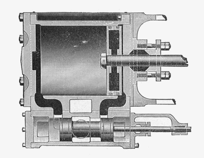
A turbocharger is a vital component in locomotive engines, leveraging exhaust gases to increase power output and fuel efficiency. It consists of several main components that work together to achieve this:

1. Turbine Wheel: The turbine wheel is driven by exhaust gases flowing through the exhaust manifold. Its rotational motion is transferred to the compressor via the shaft.

2. Compressor: The compressor draws in and compresses air, forcing it into the engine’s air intake. This increases the air pressure and density for better combustion and power output.

3. Shaft: The shaft connects the turbine wheel and the compressor, transmitting the rotational motion from the exhaust gases to the air intake.

4. Housing: The housing encloses the turbine wheel and the compressor, providing structural support and controlling the airflow. It has inlet and exhaust ports to direct the air and exhaust gases appropriately.

5. Intercooler: Sometimes used in locomotive engines, an intercooler cools down the compressed air from the compressor before it enters the combustion chamber. This increases its density, thus improving fuel efficiency and power output.

These components work intricately together to enhance the performance of locomotive engines, ensuring efficient air intake, combustion, and utilization of exhaust gases. The turbocharger is a critical part of many commercial vehicles, providing increased power and improved fuel economy.

Explanation of the functions of each turbocharger component

Each component of a turbocharger plays a vital role in maximizing the performance of a locomotive engine.

1. Turbine Wheel: The turbine wheel harnesses the energy from exhaust gases flowing through the exhaust manifold. The high-velocity gases spin the turbine wheel, converting thermal energy into mechanical energy.

2. Compressor Wheel: The compressor draws in ambient air and compresses it, increasing its pressure and density. The compressed air is then forced into the engine’s air intake, allowing for better combustion and increased power output.

3. Shaft: The shaft connects the turbine wheel and the compressor wheel, transferring the rotational motion from the exhaust gases to the air intake. It ensures synchronized operation between the turbine and compressor.

4. Snail-Shaped Housing: The snail-shaped housing encloses the turbine and compressor wheels. Its design optimizes the airflow and directs the exhaust gases and compressed air in the desired direction, enhancing engine performance.

5. Inlet and Exhaust Ports: The housing includes inlet and exhaust ports that guide the airflow. The inlet port allows ambient air to enter the compressor, while the exhaust port channels the exhaust gases to the turbine wheel.

6. Intercooler: Some locomotive engines incorporate an intercooler. It cools down the compressed air from the compressor before it enters the combustion chamber. By reducing the air temperature, the intercooler increases the air density, resulting in improved fuel efficiency and power output.

Understanding the function of each turbocharger component is crucial to optimizing the performance and efficiency of locomotive engines.

Importance of proper maintenance and care for turbocharger components

Proper maintenance and care for turbocharger components in locomotive engines are of utmost importance to ensure optimal performance and longevity. Neglecting these essential tasks can have severe consequences and lead to costly repairs or even engine failure.

Regular maintenance of turbocharger components is crucial for several reasons. Firstly, it helps prevent premature wear and damage to the components, such as the turbine and compressor wheels. Dirt and debris can accumulate in the air intake or exhaust ports, causing restricted airflow and decreased performance. Regular cleaning of these areas ensures smooth and efficient operation.

Secondly, checking for leaks is essential in maintaining turbocharger components. Any leakage of exhaust gases or compressed air can significantly affect the engine’s performance and fuel efficiency. By identifying and repairing leaks promptly, the potential damage to other engine components can be minimized.

Furthermore, regular inspection for wear and tear is essential. Over time, components like the turbine and compressor wheels may experience deterioration or imbalance, leading to reduced power output and potential damage to other engine parts. By regularly inspecting and servicing these components, issues can be identified early on and preventive measures can be taken.

In conclusion, proper maintenance and care for turbocharger components in locomotive engines are vital for maximizing performance, preventing damage, and ensuring a longer lifespan. Neglecting these essential tasks can result in decreased power output, reduced fuel efficiency, and costly repairs. Therefore, it is crucial to prioritize regular cleaning, leak detection, and inspection of these components to maintain optimal engine performance.

Turbocharger Integration with Other Locomotive Engine Components

Turbochargers play a crucial role in enhancing the performance and efficiency of locomotive engines. They work by harnessing the energy from exhaust gases to increase the intake air pressure, resulting in improved combustion and power output. However, turbocharger components do not operate in isolation. They are intricately integrated with various other engine components to ensure optimal performance. The integration involves several key aspects such as air intake systems, exhaust manifolds, exhaust aftertreatment devices, and fuel systems. Each of these components must work harmoniously to maximize the benefits of turbocharging while ensuring smooth operation and reliability. Understanding the integration of turbocharger components with other engine parts is essential for maintaining and optimizing the performance of locomotive engines.

How turbochargers work in conjunction with other key engine components

Turbochargers play a vital role in enhancing the performance of locomotive engines by increasing power output and improving fuel efficiency. These components work in conjunction with other key engine components to optimize overall performance.

Located within the exhaust manifold, turbochargers utilize the force of exhaust gases to drive a turbine that is connected to a compressor. As exhaust gases flow through the turbine, it rotates at high speeds, creating rotational motion. The compressor, on the other hand, pulls in air from the atmosphere and compresses it before sending it into the intake stroke of the engine.

The compressed air from the turbocharger allows the engine to intake a larger volume of air and fuel mixture during each combustion cycle. This results in improved power output without the need for a larger engine displacement. Additionally, turbocharged engines benefit from reduced fuel consumption, as the compressed air promotes better combustion efficiency.

Designing and optimizing turbocharger integration can present challenges. Achieving precise control over the boost pressure and ensuring compatibility with other engine components are key considerations. Proper intake and exhaust piping, as well as exhaust aftertreatment devices, must be implemented to manage air flow and reduce air pollution.

In conclusion, turbochargers, when well-integrated into locomotive engines, offer numerous benefits such as increased power output and improved fuel efficiency. However, careful consideration and engineering are necessary to overcome challenges related to turbocharger integration and to optimize overall performance.

Benefits of a well-integrated turbocharger system in a locomotive engine

A well-integrated turbocharger system in a locomotive engine offers numerous benefits, significantly enhancing its overall performance and efficiency. By utilizing exhaust gases to drive a turbine connected to a compressor, a turbocharger enables the engine to intake a larger volume of air and fuel mixture during each combustion cycle. This leads to an increase in power output without the need for a larger engine displacement.

One of the key advantages of a well-integrated turbocharger system is the improvement in fuel efficiency. The compressed air provided by the turbocharger promotes better combustion efficiency, resulting in reduced fuel consumption. This not only leads to cost savings but also contributes to a more sustainable and environmentally friendly operation by reducing emissions.

In addition to improved fuel economy, a well-integrated turbocharger system offers enhanced engine responsiveness. The increased air intake allows for faster acceleration and quicker throttle response, providing a smoother and more dynamic driving experience.

Overall, a well-integrated turbocharger system in a locomotive engine offers a range of benefits, including increased power output, enhanced fuel economy, reduced emissions, and improved engine responsiveness. This technology plays a crucial role in enhancing the performance and efficiency of locomotive engines, making them more powerful and environmentally friendly.

Challenges and considerations in designing and optimizing turbocharger integration

In designing and optimizing turbocharger integration in locomotive engines, there are several challenges and considerations that need to be taken into account. First and foremost is the need to ensure compatibility and proper fitment of the turbocharger components with the existing engine architecture. This involves designing the turbocharger system in a way that it can be seamlessly integrated into the engine without causing interference with other critical components.

Another significant consideration is the need for effective heat management. Turbochargers generate a significant amount of heat, and if not properly managed, it can lead to engine overheating and potential damage. Therefore, it is crucial to design the turbocharger system in a way that proper cooling and heat dissipation mechanisms are in place.

Furthermore, the selection of the appropriate turbocharger type and size is essential. Different locomotive engines have different power requirements, so it is crucial to select a turbocharger that can provide adequate boost pressure and airflow for optimal engine performance without causing excess turbo lag or compromising overall efficiency.

Integrating turbochargers with other key engine components such as exhaust valves, exhaust aftertreatment devices, and fuel cells also presents challenges. For example, the turbocharger system needs to be designed in a way that it does not impede the functioning of the exhaust aftertreatment system, which is crucial for meeting emission regulations. Careful consideration is required to ensure proper alignment and connection of these components to maintain their individual efficiency and effectiveness.

Overall, designing and optimizing turbocharger integration in locomotive engines involves considering factors such as compatibility, heat management, proper sizing, and integration with other engine components to achieve optimal performance and efficiency. By addressing these challenges and considerations, the turbocharger system can effectively enhance the power output and fuel efficiency of locomotive engines.

Future Trends in Turbocharger Technology for Locomotive Engines

Introduction:

The constant drive for improved performance and efficiency in locomotive engines has led to ongoing advancements in turbocharger technology. As technology continues to evolve, future trends in turbocharger design and functionality are expected to focus on enhancing fuel efficiency, reducing emissions, and optimizing power output. This article will explore some of the emerging trends in turbocharger technology for locomotive engines, including the use of hybrid turbochargers, advanced engine technologies, and the integration of turbochargers with alternative power sources such as electric engines and fuel cells. Additionally, the importance of considering heat management and component integration within the turbocharger system will be highlighted. By staying abreast of these future trends, locomotive engine manufacturers can continue to develop more efficient and environmentally friendly turbocharger systems to meet the demands of the ever-changing industry.

Overview of the latest advancements in turbocharger technology for locomotive engines

Overview of the Latest Advancements in Turbocharger Technology for Locomotive Engines

Turbocharger technology has seen significant advancements in recent years, particularly in the realm of locomotive engines. These advancements have not only improved fuel efficiency but have also enhanced overall engine performance and reduced air pollution. One of the key areas of development has been in the field of combustion engineering.

Combustion engineering advancements have allowed for more precise fuel mixture control, resulting in optimized combustion efficiency. This, in turn, leads to improved power output and reduced fuel consumption. Turbochargers play a critical role in this process by increasing the air intake, enabling higher engine speeds, and generating more rotational motion in the engine.

Different types of turbochargers have emerged as well. These include hybrid turbochargers, electric turbochargers, and turbochargers with advanced geometries. Hybrid turbochargers combine traditional exhaust-driven turbochargers with electrically driven compressors, providing improved response and reduced turbo lag. Electric turbochargers use electric motors to drive the compressor, allowing for greater control over boost pressure. Turbochargers with advanced geometries, such as variable geometry and twin-scroll turbos, optimize air flow and improve overall engine efficiency.

The adoption of these new turbocharger technologies brings several benefits to locomotive engines. These include increased power output, improved fuel economy, and reduced emissions. However, there are also some challenges associated with the adoption of new technologies, such as cost implications, integration with existing engine equipment, and the need for specialized maintenance and repair.

In conclusion, advancements in turbocharger technology for locomotive engines have brought about numerous benefits, including better fuel efficiency and reduced air pollution. Combustion engineering breakthroughs, coupled with different types of turbochargers, have played a key role in achieving these advancements. While there are challenges to overcome, the potential advantages make investing in these new turbocharger technologies a compelling option for locomotive engines.

Potential benefits and challenges of adopting new turbocharger technologies

The adoption of new turbocharger technologies in locomotive engines brings several potential benefits and challenges. On the benefits side, these advancements can significantly improve both the performance and efficiency of locomotive engines. Turbocharger advancements, such as hybrid turbochargers, electric turbochargers, and turbochargers with advanced geometries, offer increased power output, improved fuel economy, and reduced emissions.

By increasing the air intake and generating more rotational motion in the engine, turbochargers enable higher engine speeds and optimize combustion efficiency. The precise control of the fuel mixture and boost pressure provided by these new turbocharger technologies result in enhanced power output and reduced fuel consumption.

However, there are also challenges associated with the integration of these new turbocharger technologies. Firstly, there may be cost implications, as the adoption of advanced turbochargers may require significant investment. Additionally, integrating new technologies into existing engine equipment may pose compatibility issues and require modifications or replacements. Lastly, specialized maintenance and repair may be needed to ensure the proper functioning of these advanced turbocharger systems.

In summary, the adoption of new turbocharger technologies in locomotive engines offers potential benefits such as improved performance and efficiency. However, industry stakeholders must also consider the challenges of cost, integration, and specialized maintenance.

Predictions for the future of turbochargers in locomotive engine design and performance

Predictions for the future of turbochargers in locomotive engine design and performance are promising. As turbocharger technology continues to advance in the automobile industry, these advancements will undoubtedly find their way into locomotive engines.

One potential future development is the use of smaller, more efficient turbochargers that can deliver increased power and improved fuel efficiency. These turbochargers may incorporate advanced materials and aerodynamic designs to optimize air flow and minimize weight. Additionally, advancements in turbine and compressor technology could lead to even greater efficiency gains.

Another important area of development is the integration of hybrid and electric technologies with turbochargers. Hybrid turbo engines, for example, combine the benefits of a turbocharger with an electric motor to provide instant torque and improved fuel economy. Furthermore, the use of fuel cells in conjunction with turbochargers could revolutionize locomotive engines by offering zero-emission solutions.

Moreover, future turbocharger designs may incorporate advanced control systems and sensors to further optimize performance. These systems would continuously monitor and adjust boost pressure, air flow, and other parameters to maximize efficiency and reduce emissions. Additionally, machine learning algorithms may be utilized to optimize turbocharger performance based on real-time driving conditions.

Overall, the future of turbochargers in locomotive engine design and performance looks promising. Advancements in technology will undoubtedly result in more efficient, powerful, and environmentally friendly locomotive engines, offering improved performance and reduced emissions for the commercial vehicle and railway industries.

WABCO 6CD4UC Compressor – Expressor

WABCO 6CD4UC Compressor-Expressor

Introduction to the WABCO 6CD4UC Compressor-Expressor

The WABCO 6CD4UC Compressor-Expressor is a powerful and reliable compressor-expressor designed for various industrial applications. With its cutting-edge technology and exceptional performance, this device has become a popular choice among professionals in the industry.

Overview of the WABCO 6CD4UC Compressor-Expressor

The WABCO 6CD4UC Compressor-Expressor is a compact and efficient device that combines the functions of a compressor and an expressor. It is widely used in manufacturing, construction, and other industries where compressed air is a vital component.

This compressor-expressor features a robust construction that ensures durability and long-term reliability. It is designed to deliver high-pressure air, making it suitable for a wide range of applications. The 6CD4UC model is known for its advanced technology and superior performance, making it a top choice for professionals who require efficient and reliable compressed air solutions.

This device is equipped with advanced features such as automatic condensate drain, oil filtration system, and thermal protection. These features enhance the reliability and efficiency of the device while ensuring smooth operation and minimal maintenance requirements.

Importance and benefits of using a compressor-expressor

Using a compressor-expressor like the WABCO 6CD4UC offers several advantages in industrial applications. Here are some key benefits:

  1. Increased productivity: The compressor-expressor enables faster and more efficient operation, saving time and improving overall productivity.
  2. Energy efficiency: The WABCO 6CD4UC is designed with advanced energy-saving features, reducing energy consumption and lowering operating costs.
  3. Versatility: This compressor-expressor is versatile and can be used for various applications, including pneumatic tools, paint spraying, and air-powered machinery.
  4. Reliability: With its durable construction and advanced technology, the WABCO 6CD4UC ensures reliable and consistent performance even in demanding working conditions.

In conclusion, the WABCO 6CD4UC Compressor-Expressor is a reliable and efficient device that offers numerous benefits for industrial applications. Its advanced features and superior performance make it a top choice for professionals looking for a high-quality compressor-expressor solution.

WABCO 6CD4UC Compressor-Expressor Features and Specifications

WABCO 6CD4UC Compressor-Expressor Features and Specifications

Detailed specifications of the WABCO 6CD4UC Compressor-Expressor

The WABCO 6CD4UC Compressor-Expressor is a powerful and reliable compressor designed for heavy-duty commercial vehicles. Here are the detailed specifications of this impressive compressor:

  1. Capacity: The 6CD4UC Compressor-Expressor has a maximum capacity of 15.5 cubic feet per minute (CFM). This high capacity allows for efficient air compression and quick recovery times.
  2. Operating Range: It operates at a continuous air pressure range of 80 to 145 pounds per square inch (psi). This wide operating range ensures optimal performance in various applications.
  3. Speed: The compressor operates at a maximum rotational speed of 4,000 revolutions per minute (RPM). This high-speed operation enables fast and efficient compression.
  4. Energy Efficiency: The 6CD4UC Compressor-Expressor is designed to be energy-efficient, helping to reduce fuel consumption and operating costs.
  5. Reliability: WABCO is known for manufacturing high-quality and reliable products, and the 6CD4UC Compressor-Expressor is no exception. It is built to withstand harsh operating conditions and provide consistent performance.

Key features and functions of the compressor-expressor

The WABCO 6CD4UC Compressor-Expressor offers various features and functions that enhance its performance and reliability. Here are some key highlights:

  1. Advanced Technology: It is equipped with advanced technology that ensures precise and efficient air compression, providing consistent air supply for braking systems.
  2. Integrated Cooling System: The compressor-expressor features an integrated cooling system that helps maintain optimum operating temperatures, preventing overheating and ensuring long-lasting performance.
  3. Compact Design: Despite its powerful performance, the 6CD4UC Compressor-Expressor has a compact design, making it suitable for space-constrained installations.
  4. Easy Maintenance: The compressor-expressor is designed for easy maintenance, with accessible components and user-friendly features that simplify servicing and reduce downtime.
  5. Wide Application: It is suitable for a wide range of heavy-duty commercial vehicles, including trucks, buses, and trailers.

In conclusion, the WABCO 6CD4UC Compressor-Expressor is a reliable and efficient compressor that delivers consistent performance in heavy-duty applications. Its impressive features and specifications make it a valuable component for vehicles that demand powerful and reliable air compression.

WABCO 6CD4UC Compressor-Expressor

Performance and Efficiency of the WABCO 6CD4UC Compressor-Expressor

How the WABCO 6CD4UC Compressor-Expressor enhances performance

When it comes to optimizing your vehicle’s performance, the WABCO 6CD4UC Compressor-Expressor is a game-changer. This advanced compressor-expressor system is designed to deliver superior performance and enhance the overall efficiency of your vehicle’s braking and air supply systems.

The WABCO 6CD4UC Compressor-Expressor boasts a robust design and state-of-the-art technology that ensures reliable and consistent performance. It provides high air delivery rates, allowing for quick and efficient brake system response. This means faster brake application and improved braking performance, resulting in enhanced safety on the road.

Additionally, this compressor-expressor system is engineered to withstand extreme conditions and heavy-duty applications. Its durable construction and advanced cooling system prevent overheating, ensuring optimal performance even in the most demanding environments. This reliability is crucial for vehicles that operate in industries such as construction, mining, and transportation.

Energy efficiency and cost-effectiveness of the compressor-expressor

In addition to its outstanding performance, the WABCO 6CD4UC Compressor-Expressor also prioritizes energy efficiency and cost-effectiveness. By utilizing advanced technology, this system maximizes energy output while minimizing energy consumption, resulting in reduced fuel usage. This not only benefits the environment by reducing carbon emissions but also saves you money in the long run.

Furthermore, the WABCO 6CD4UC Compressor-Expressor is designed with longevity and low maintenance in mind. Its high-quality components and efficient operation ensure a longer lifespan and fewer breakdowns, reducing repair and replacement costs. This makes it a cost-effective choice for businesses and individuals looking for a reliable and durable compressor-expressor solution.

In conclusion, the WABCO 6CD4UC Compressor-Expressor is a high-performance and energy-efficient system that enhances the overall performance of your vehicle’s braking and air supply systems. With its reliable operation, durability, and cost-effectiveness, it is an excellent choice for various industries and applications.

Installation and Maintenance of the WABCO 6CD4UC Compressor-Expressor

Installation and Maintenance of the WABCO 6CD4UC Compressor-Expressor

Steps to install and set up the WABCO 6CD4UC Compressor-Expressor

Installing and setting up the WABCO 6CD4UC Compressor-Expressor is a straightforward process. Here are the essential steps you need to follow:

  1. Prepare the installation area: Clear the area where you plan to install the compressor-expressor. Make sure there is enough space for proper ventilation and access to the necessary connections.
  2. Mount the compressor-expressor: Securely mount the compressor-expressor in the desired location. Ensure that it is positioned correctly according to the manufacturer’s guidelines.
  3. Connect the electrical supply: Follow the wiring diagram provided by WABCO to connect the electrical supply to the compressor-expressor. Be sure to use the appropriate wires and connectors to prevent any electrical issues.
  4. Connect air lines: Attach the air lines to the compressor-expressor according to the instructions provided. Make sure all connections are tight and secure to prevent air leaks.
  5. Test the system: Once the installation is complete, test the system to ensure proper operation. Check for any leaks or abnormal sounds and address them immediately.

Tips for proper maintenance and care of the compressor-expressor

Regular maintenance is crucial to ensure the optimal performance and longevity of the WABCO 6CD4UC Compressor-Expressor. Here are some tips to follow:

  1. Check and clean the air filters: Regularly inspect the air filters and clean or replace them as needed. Clean filters help maintain air quality and prevent debris from damaging the compressor-expressor.
  2. Inspect for leaks: Routinely check for any air leaks in the system. Leaks can impact the compressor-expressor’s efficiency and should be repaired promptly.
  3. Monitor the oil level: Keep an eye on the oil level in the compressor-expressor and refill or change it according to the manufacturer’s recommendations. Proper lubrication is essential for smooth operation.
  4. Keep the compressor-expressor clean: Clean the exterior of the compressor-expressor regularly to remove dirt and debris that could interfere with its performance.
  5. Follow recommended maintenance schedules: Refer to the manufacturer’s maintenance schedule and perform the recommended maintenance tasks at the specified intervals. This includes checking and adjusting belt tension, inspecting hoses, and ensuring proper system pressure.

By following these steps for installation and tips for maintenance, you can ensure that your WABCO 6CD4UC Compressor-Expressor operates efficiently and effectively for years to come.

Applications and Industries that Benefit from the WABCO 6CD4UC Compressor-Expressor

Applications and Industries that Benefit from the WABCO 6CD4UC Compressor-Expressor

Various industries and sectors where the compressor-expressor is used

The WABCO 6CD4UC Compressor-Expressor is a versatile and reliable component that is used in a wide range of industries and sectors. Its high-performance capabilities make it an ideal choice for various applications. Some of the industries that benefit from this compressor-expressor include:

  1. Automotive: The automotive industry relies on the WABCO 6CD4UC Compressor-Expressor for its air suspension systems and air braking systems. The compressor-expressor ensures smooth and efficient operation, enhancing overall safety and performance.
  2. Transportation and logistics: In the transportation and logistics sector, this compressor-expressor is used in heavy-duty trucks, buses, and trailers. It provides the necessary air pressure to enable efficient braking and suspension systems, ensuring a smooth and comfortable ride for passengers and cargo.
  3. Construction: Construction vehicles and equipment often require air systems to perform various functions. The WABCO 6CD4UC Compressor-Expressor is commonly used in construction machinery such as excavators, loaders, and dump trucks to power air brakes, suspension systems, and pneumatic tools.

Specific applications and advantages in each industry

In the automotive industry, the WABCO 6CD4UC Compressor-Expressor ensures optimal performance of air suspension systems by providing reliable air pressure. This results in improved ride comfort, stability, and safety, making it an essential component for luxury vehicles and heavy-duty trucks.

In the transportation and logistics sector, the compressor-expressor plays a critical role in ensuring the efficiency and safety of braking systems. It enables precise modulation of air pressure, allowing for quick and reliable braking, which is crucial for large vehicles carrying heavy loads.

Construction vehicles, such as excavators and loaders, require robust air systems to power various functions. The WABCO 6CD4UC Compressor-Expressor provides the necessary air pressure for pneumatic tools, enabling efficient operation on construction sites.

Overall, the WABCO 6CD4UC Compressor-Expressor is a trusted component used in a wide range of applications. Its reliability, performance, and versatility make it an invaluable choice for industries that require efficient air systems to ensure safety, comfort, and productivity.

Comparing the WABCO 6CD4UC Compressor-Expressor with Other Compressor-Expressor Models

When it comes to compressor-expressor models, the WABCO 6CD4UC stands out in terms of performance, reliability, and features. Let’s take a closer look at how it compares to other similar models on the market.

Examination of similar compressor-expressor models on the market

In the market for compressor-expressor models, there are several options to choose from. However, the WABCO 6CD4UC stands apart from the rest due to its unique features and capabilities.

While other models may offer decent performance, the WABCO 6CD4UC goes above and beyond. Its advanced technology allows for superior compression and expression, ensuring efficient operation and optimal functionality. Other models may struggle to deliver the same level of performance and reliability.

Key differences and advantages of the WABCO 6CD4UC Compressor-Expressor

Here are some key differences and advantages of the WABCO 6CD4UC Compressor-Expressor:

  1. Reliability: The WABCO 6CD4UC is known for its exceptional reliability. Its robust design and high-quality construction ensure long-lasting performance, making it a trustworthy choice for various applications.
  2. Efficiency: With its advanced technology, the WABCO 6CD4UC operates with optimal efficiency, ensuring minimal energy consumption. This not only saves costs but also reduces the environmental impact.
  3. Quiet Operation: Noise can be a significant concern when it comes to compressor-expressor models. The WABCO 6CD4UC is designed with noise reduction features, providing a quieter operation for a more comfortable working environment.
  4. Compact Design: The compact size of the WABCO 6CD4UC allows for easy installation and integration into various systems. Its versatility makes it suitable for a wide range of applications.

In summary, the WABCO 6CD4UC Compressor-Expressor stands out from other models on the market due to its superior performance, reliability, efficiency, quiet operation, and compact design. Whether you need a compressor-expressor for industrial, automotive, or other applications, the WABCO 6CD4UC is a top choice that delivers exceptional results.

Frequently Asked Questions about the WABCO 6CD4UC Compressor-Expressor

Common queries and concerns about the compressor-expressor

If you are searching for a reliable and efficient compressor-expressor for your vehicle, you may have come across the WABCO 6CD4UC. Here are some common questions and concerns that users often have when considering this product.

  1. What is the purpose of the WABCO 6CD4UC Compressor-Expressor?
    The WABCO 6CD4UC Compressor-Expressor is a vital component in the air brake system of heavy-duty vehicles. It is responsible for pressurizing the air that powers the braking system, ensuring efficient and reliable operation.
  2. Is the WABCO 6CD4UC Compressor-Expressor compatible with my vehicle?
    The WABCO 6CD4UC Compressor-Expressor is designed to be compatible with a wide range of heavy-duty vehicles. However, it is always recommended to consult the manufacturer or your vehicle’s manual to ensure compatibility before making a purchase.
  3. What are the key features of the WABCO 6CD4UC Compressor-Expressor?The WABCO 6CD4UC Compressor-Expressor is known for its durability, high performance, and low noise emission. It is designed to withstand harsh operating conditions, making it suitable for demanding applications.

Informative answers and solutions to these questions

  1. Guaranteeing optimal air pressure: The WABCO 6CD4UC Compressor-Expressor is specifically engineered to deliver consistent and reliable air pressure for effective braking performance, ensuring the safety of your vehicle and its occupants.
  2. Enhanced efficiency and productivity: The exceptional performance of the WABCO 6CD4UC allows for quicker pressurization, resulting in shorter brake response times. This can lead to increased productivity, especially in commercial vehicle applications.
  3. Noise reduction technology: The WABCO 6CD4UC Compressor-Expressor is designed with advanced noise reduction technology, ensuring a quieter operation. This feature contributes to a more comfortable driving experience and reduces noise pollution.
  4. Trusted brand: WABCO is a renowned and trusted brand in the automotive industry, known for their high-quality products and innovative solutions. Choosing the WABCO 6CD4UC Compressor-Expressor means investing in a reliable and long-lasting component for your vehicle.

In conclusion, the WABCO 6CD4UC Compressor-Expressor is a high-performance and dependable choice for your vehicle’s air brake system. With its excellent features and trusted brand reputation, it offers enhanced safety, efficiency, and durability.

Conclusion

Summary of the key points and benefits of the WABCO 6CD4UC Compressor-Expressor

The WABCO 6CD4UC Compressor-Expressor is a reliable and efficient compressor-expressor that offers several key benefits. Its compact size makes it easy to install in various vehicles, while its advanced technology ensures optimal performance. With a maximum working pressure of 12.5 bar and a flow rate of 1100 l/min, it provides consistent and powerful air compression for various applications.

One of the main advantages of the WABCO 6CD4UC Compressor-Expressor is its durability and longevity. Built with high-quality materials and rigorous manufacturing processes, this compressor-expressor is designed to withstand harsh conditions and deliver exceptional performance even in demanding environments.

Furthermore, this compressor-expressor is known for its energy efficiency, helping businesses save on operational costs and reduce their environmental impact. Its intelligent control system allows for precise pressure regulation, ensuring optimal air supply while minimizing energy consumption.

Final thoughts and recommendation on the compressor-expressor

With its outstanding performance, durability, and energy efficiency, the WABCO 6CD4UC Compressor-Expressor is a highly recommended choice for businesses in need of reliable air compression solutions. Whether used in heavy-duty trucks, construction equipment, or industrial applications, this compressor-expressor delivers excellent results.

In conclusion, investing in the WABCO 6CD4UC Compressor-Expressor can provide long-term benefits and contribute to the overall efficiency and productivity of your operations. Its advanced technology, durability, and energy efficiency make it a cost-effective and environmentally friendly choice. Consider integrating the WABCO 6CD4UC Compressor-Expressor into your equipment and experience the difference it can make in your business.

Fuse Links in Locomotive Engines: Safety, Maintenance & More

Fuse Links in Locomotive Engines: Safety, Maintenance & More

Introduction

In locomotive engines, ensuring safety is of utmost importance to protect both passengers and crew. One crucial component that contributes to the overall safety and reliability of locomotives is the fuse link. Fuse links are vital for short-circuit protection and overcurrent protection, safeguarding the engine from potential electrical problems. With a wide range of fuse types available, railway operators can choose the most suitable fuse link based on the melting temperature, current rating, and specific requirements of their locomotive engines. Routine maintenance of fuse links is essential to ensure their proper functioning and to prevent potential breakdowns that could lead to costly repairs and downtime. Maintenance and repair workers with experience in the maintenance field play a vital role in conducting regular inspections and replacing worn out or damaged fuse links promptly. By prioritizing fuse protection and adhering to strict safety procedures, both operators and passengers can have peace of mind and confidence in the reliable operation of locomotive engines.

Understanding the Significance of Fuse Links

Fuse links play a vital role in providing circuit protection and preventing electrical accidents in locomotive engines. These small but crucial components help safeguard the electrical system by interrupting the flow of excessive current, thus preventing damage to equipment and potential fire hazards.

There are different types of fuse links commonly used in railway safety, including blade fuses, cartridge fuses, and fusible links. Blade fuses are typically found in passenger trains and provide short-circuit protection. Cartridge fuses, on the other hand, offer overcurrent protection and can be found in track roadway maintenance machines and other railway equipment. Fusible links are designed to melt at specific temperatures and are commonly used in locomotive engines to protect against short-circuit conditions.

Compliance with railway safety standards is of utmost importance in order to ensure the proper functioning of fuse links. Routine maintenance and inspection are necessary to ensure that the fuse links are in good working condition and provide the required protection. Regular checks should be conducted to verify the melting range, current rating, and overall integrity of the fuse links. Any non-complying condition should be addressed immediately to avoid potential accidents.

In conclusion, fuse links are critical components in locomotive engines that provide circuit protection and prevent electrical accidents. Understanding their significance and ensuring compliance with railway safety standards, along with routine maintenance and inspection, are essential for the safe operation of locomotive engines.

Overview of What to Expect in This Guide

In this guide, we will delve into an important aspect of electronic security systems (ESSs) – the break times of safety fuse links. Understanding the break times is crucial for ensuring the effectiveness of ESSs in critical infrastructure facilities.

First, we will explore the significance of selecting reliable fuse links for ESSs. The safety fuse links act as a protective barrier in ESSs, preventing damage and ensuring the smooth operation of these systems. We will discuss the various factors that make reliable fuse links an essential component in safeguarding critical infrastructure.

Next, we will discuss the impact of economic factors on the protective properties of safety fuse links in ESSs. Economic considerations often play a role in the selection and maintenance of fuse links. We will analyze how cost-effectiveness can be achieved while prioritizing the safety and reliability of ESSs.

By the end of this guide, you will have a comprehensive understanding of the importance of break times in safety fuse links for ESSs, as well as the factors to consider when selecting and maintaining these crucial components in critical infrastructure facilities. Stay tuned for the in-depth discussion on the reliability and economic aspects of safety fuse links in ESSs.

Why Proper Fuse Link Knowledge is Crucial

Proper fuse link knowledge is crucial when it comes to locomotive engines and their safe operation. Fuse links play a significant role in protecting the engine from potential damage caused by short circuits and voltage spikes.

Understanding the importance of fuse links allows maintenance workers and operators to select the appropriate type of fuse link for each specific application. Different locomotive engines may require different fuse link configurations based on their power requirements and potential risks.

Fuse links act as a safety mechanism that interrupts the flow of current when it exceeds a certain threshold. This prevents electrical components from overheating or becoming damaged, ensuring the engine operates smoothly and efficiently. Without the proper fuse link knowledge, operators may run the risk of not adequately protecting the locomotive engine from electrical failures.

The consequences of not understanding the importance of fuse links in maintaining safe railway operations can be severe. Inadequate fuse protection can result in damage to the engine’s electrical system, leading to costly repairs and extended periods of downtime. Furthermore, it can also pose significant safety risks to the train passengers and crew.

In conclusion, proper fuse link knowledge is crucial in ensuring the safe and efficient operation of locomotive engines. Understanding the significance of fuse links in protecting against short circuits and voltage spikes is essential to maintain safe railway operations and prevent unnecessary damage and risks.

Fundamentals of Fuse Links

Introduction:

Understanding the fundamentals of fuse links is essential for maintaining the safety and efficiency of locomotive engines. Fuse links act as crucial safety mechanisms that protect the electrical components of the engine from overheating or becoming damaged due to excessive current flow. By interrupting the current when it exceeds a certain threshold, fuse links prevent potential electrical failures and ensure smooth operation. This not only prevents costly repairs and downtime but also ensures the safety of train passengers and crew. In this article, we will explore the importance of fuse links in locomotive engines, including their role in short-circuit and overcurrent protection, different fuse types, and the significance of routine maintenance. With a solid understanding of fuse link fundamentals, maintenance workers and operators can choose the appropriate fuse link configurations for various applications, ensuring the reliable and safe operation of railway systems.

What Are Fuse Links?

Fuse links are essential safety devices used in locomotive engines to protect electrical circuits from overcurrents and short circuits. They are designed to interrupt the flow of electricity when the current exceeds safe levels, preventing damage to the engine and ensuring the safety of both passengers and operators.

The purpose of fuse links is to provide reliable and effective overcurrent protection. When a fuse link detects a current surge beyond its current rating, it quickly melts, creating an open circuit and preventing the excessive flow of electricity. This action breaks the circuit and stops the flow of current to sensitive components, protecting them from damage.

Fuse links come in various types, including fast-acting and slow-blow fuses. Fast-acting fuse links are designed to react quickly to overcurrents and short circuits, while slow-blow fuse links are intended to tolerate temporary surges in current without unnecessarily tripping.

In locomotive engines, fuse links are crucial for the safe operation of the various electrical systems. By providing a reliable and effective means of preventing overcurrents and short circuits, these fuse links help safeguard the engine from damage and ensure the safety of everyone on board.

Overall, fuse links play a vital role in maintaining the safety and functionality of locomotive engines. Regular routine maintenance, including checking and replacing fuse links as needed, helps ensure the continued protection of electrical circuits and reduces the risk of accidents or engine malfunctions.

Types of Fuse Links in Locomotive Engines

There are different types of fuse links used in locomotive engines, each designed to provide reliable overcurrent protection for specific applications. One such type is the NH fuse handle for NH fuses. These fuse links are commonly used in locomotive engines due to their high breaking capacity and excellent short-circuit protection.

Another type is the DNPVXL series knife type contact fuse, specifically designed for new energy applications in locomotive engines. These fuse links have a compact design and provide efficient protection against overcurrents and short circuits.

For higher voltage applications, the NT1-P and NT3-P AC1140V fused links are commonly used. These fuse links have high voltage ratings and are capable of providing reliable overcurrent protection in locomotive engines.

A typical fuse link consists of various components, including the contact board, fuse tube, quartz, fuse element, cover, and link fuse. These components work together to quickly detect overcurrents and short circuits and break the circuit to prevent damage to sensitive electrical components.

When it comes to reliable manufacturers of fuse links, GRL stands out with over 30 years of experience in the field. GRL offers a wide range of fuse links, including those specifically designed for locomotive engines, ensuring safe and efficient operation.

In conclusion, fuse links play a critical role in providing overcurrent protection in locomotive engines. Whether it’s the NH fuse handle, DNPVXL series contact fuse, or NT1-P and NT3-P AC1140V fused links, choosing the right type is essential to ensure the safety and smooth functioning of electrical systems in locomotive engines.

How Fuse Links Work

Fuse links play a crucial role in ensuring the safety and efficient operation of locomotive engines. These components protect against voltage spikes and extreme current overload by acting as inline circuit fuses in the vehicle’s wiring harness.

When a voltage spike or current overload occurs, the fuse link senses the excessive flow of electricity and responds by melting its link fuse. This breaking of the circuit prevents further damage to sensitive electrical components.

Fuse links are designed to have a lower melting temperature than the rest of the wiring harness. This intentional weak link ensures that the fuse link fails before any other components, thereby protecting the entire electrical system from potential harm.

Once a fuse link has melted, it is important to replace it promptly. Blown fuse links must be replaced with new ones of the same current rating to restore proper circuit protection. Regular maintenance and inspection of fuse links are essential to ensure their continued function.

In conclusion, fuse links act as crucial safety measures in locomotive engines, protecting against voltage spikes and extreme current overload. These inline circuit fuses play a vital role in safeguarding the vehicle’s electrical system and should be regularly maintained and replaced when necessary.

The Role of Fuse Links in Railway Safety

Fuse links play a crucial role in ensuring the safety of railway systems. In locomotive engines, where the flow of electricity is abundant, fuse links provide short-circuit and overcurrent protection. These devices are designed to have a lower melting temperature than the rest of the wiring harness, serving as intentional weak links. In the event of a voltage spike or current overload, the fuse link detects the excessive flow and melts, breaking the circuit and preventing further damage to sensitive electrical components. This critical function safeguards the entire electrical system from potential harm. Understanding the importance of fuse links in railway safety, routine maintenance and inspection are essential. Blown fuse links should be promptly replaced with new ones of the same current rating to restore proper circuit protection. By ensuring the continued function of fuse links through regular maintenance, railway operators can guarantee the safety and reliability of passenger trains and track roadway maintenance machines.

Ensuring Safe Railway Operations

Ensuring Safe Railway Operations is of utmost importance in the rail industry. Commercially available electric-drive vehicles in the United States must adhere to strict safety requirements and standards. These requirements are set to maintain the safety of passengers, crew members, and the overall operational efficiency of the railway system.

One critical aspect of ensuring safe operations is the use of high-quality solutions that can withstand the harsh operating environments in the rail industry. These solutions must comply with global railway standards to ensure seamless integration into existing systems and maximize safety.

Several relevant standards apply to electric-drive vehicles in the rail industry, such as EN-50155, AREMA, RIA12, STM-E 001, and GOST. These standards cover various aspects of safety, including electrical, mechanical, and environmental requirements. Compliance with these standards ensures that the vehicles meet the necessary safety regulations and operate reliably under different conditions.

By adhering to safety requirements and utilizing high-quality solutions, railway operators can provide a safe and efficient transportation system for the passengers and crew members. This commitment to safety is crucial in maintaining customer confidence and promoting the overall growth and success of the rail industry.

Fuse Links vs. Electrical Accidents

Fuse links play a crucial role in ensuring the safety of locomotive engines by acting as protective devices that cut off circuits in case of faults. In contrast, electrical accidents can cause significant damage to electrical components or circuits.

Electrical accidents in locomotive engines can occur due to various reasons, such as short circuits or overloads. Short circuits happen when there is an unintended connection between the positive and negative terminals of a circuit, resulting in excessive current flow. Overloads occur when a circuit carries more current than it is designed to handle, leading to overheating and potential damage.

Using fuse links is of utmost importance for prevention and protection against electrical accidents. These small devices are designed to melt and break the circuit when excessive current passes through them. By doing so, they effectively prevent further damage to the electrical components and mitigate the risk of electrical accidents.

Fuse links act as the first line of defense, swiftly cutting off the circuit and protecting the surrounding electrical components from overheating and damage. They provide reliable short-circuit and overcurrent protection, reducing the risk of electrical accidents and ensuring the safe operation of locomotive engines.

In conclusion, while electrical accidents can cause significant damage to electrical components or circuits, fuse links act as protective devices to cut off circuits in case of faults. By using fuse links, locomotive engines can prevent and protect against electrical accidents, ensuring the safety and reliability of their electrical systems.

Compliance with Railway Safety Standards

Compliance with railway safety standards is of utmost importance in ensuring the safety of workers and the proper functioning of locomotive engines. Railway operations are governed by specific safety requirements and regulations that aim to minimize risks and accidents.

On-track safety programs play a crucial role in maintaining safe railway operations. These programs include various safety procedures and protocols that must be followed by all personnel working on or near railway tracks. These programs ensure that workers are trained on safety practices, equipped with necessary protective gear, and aware of potential hazards.

Railway safety regulations outline the responsibilities of railway operators, employees, and contractors in maintaining a safe working environment. Compliance with these regulations ensures that safety measures are in place to mitigate risks associated with locomotive engine operations.

By adhering to safety standards and regulations, railway operators can reduce the occurrence of accidents and protect workers from harm. These standards also help facilitate smooth and efficient transportation of passengers and cargo.

In conclusion, compliance with railway safety standards is essential for maintaining a safe working environment and ensuring the proper functioning of locomotive engines. Railway operators must prioritize safety by implementing on-track safety programs and following safety regulations to protect workers and prevent accidents.

Maintaining Fuse Links for Reliability

Maintaining Fuse Links for Reliability

Fuse links are an integral component in locomotive engines, providing crucial protection against short-circuits and overcurrent situations. To ensure their reliability, routine maintenance of fuse links is essential. Regular inspections and testing should be conducted to verify their functionality and replace any damaged or worn-out fuses. Proper maintenance of fuse links helps prevent malfunctions that could lead to disrupted operations or even accidents. Additionally, maintaining fuse links can significantly reduce maintenance costs by identifying issues early on and preventing further damage. By prioritizing the safety and reliability of fuse links in locomotive engines, operators can ensure the efficient and uninterrupted movement of passenger and cargo trains while protecting the well-being of maintenance and repair workers.

Regular Inspection of Fuse Links

Regular inspection of fuse links in locomotive engines is of utmost importance for maintaining safety and preventing electrical issues. Fuse links serve as a protective measure against short-circuit and overcurrent situations, ensuring the safety of both the locomotive and the passengers.

During routine maintenance, conducting a thorough inspection of fuse links is crucial. This involves visually checking for any signs of damage, such as cracks or melting, which could compromise their effectiveness. Fuse links should also be checked for their melting temperature and current rating to ensure they meet the specified requirements.

To detect worn or faulty fuse links, the use of a multimeter is recommended. By measuring the continuity of the fuse link, any break in the circuit can be easily identified. Additionally, checking the resistance value can indicate if the fuse link is still intact and in good working condition.

Regular inspection of fuse links not only ensures that maximum protection is provided against electrical issues, but it also helps in minimizing maintenance costs. By identifying potential problems early on, repairs or replacements can be done promptly, preventing further damage to the locomotive engine and reducing the risk of power disruptions.

In conclusion, a regular inspection of fuse links in locomotive engines is vital for maintaining safety and preventing electrical issues. By following proper inspection procedures, potential problems can be detected, and suitable actions can be taken to ensure the smooth and safe operation of the locomotive engine.

Signs of Worn or Faulty Fuse Links

Signs of Worn or Faulty Fuse Links in Locomotive Engines

During routine maintenance and inspection of locomotive engines, being aware of the signs of worn or faulty fuse links is crucial. Identifying these signs promptly can help prevent potential issues and ensure the safety and efficiency of the engine. Here are some common signs to watch out for:

1. Visual Damage: Look for any visible signs of damage to the fuse link, such as cracks, discoloration, or melting. These can indicate that the fuse link has been compromised and may no longer provide adequate protection against short circuits or overcurrents.

2. Inconsistent Continuity: Testing the continuity of the fuse link using a multimeter can reveal any breaks in the circuit. If the multimeter indicates an open circuit, it suggests that the fuse link has worn out and needs replacement.

3. Unusual Resistance Value: A well-functioning fuse link should have a relatively low resistance value. If the resistance value is unusually high, it may indicate that the fuse link has become worn or damaged.

4. Power Disruptions: Frequent power disruptions or blown fuses can also be a sign of worn or faulty fuse links. If the engine experiences recurring electrical issues, it is advisable to thoroughly inspect the fuse links for any potential problems.

By being vigilant during routine maintenance and inspection, these signs of worn or faulty fuse links can be easily identified. Addressing these issues promptly can help avoid costly repairs, ensure operational safety, and maintain the overall efficiency of the locomotive engine.

Replacing and Upgrading Fuse Links

Replacing and upgrading fuse links in locomotive engines is a critical procedure in maintaining safe and reliable railway operations. As part of routine maintenance, it is important to identify and address worn or faulty fuse links promptly to prevent electrical issues and ensure the engine’s efficiency.

The process of replacing worn or faulty fuse links involves several steps. First, it is essential to select high-quality replacements that meet the specific requirements of the locomotive engine. This ensures that the fuse links provide the necessary short-circuit and overcurrent protection.

Next, troubleshooting electrical issues is crucial to identify the root cause of the problem. This may involve conducting tests to check continuity, resistance, and voltage levels. By pinpointing the issue, proper replacements can be installed to restore the engine’s electrical system to full functionality.

Regular inspections and maintenance can help in identifying any signs of wear or damage in fuse links. By proactively replacing and upgrading these components, locomotive engines can operate safely and reliably. This procedure significantly contributes to the overall safety and efficiency of the railway system.

Troubleshooting Electrical Issues

Troubleshooting Electrical Issues in Locomotive Engines

When dealing with locomotive engines, it is crucial to effectively troubleshoot electrical issues to ensure the smooth operation and safety of the system. Electrical problems can result in malfunctions, decreased performance, and potential safety hazards. To troubleshoot these issues, various tests and inspections are performed to identify the root cause of the problem. This may include checking continuity, resistance, and voltage levels in different components and circuits. By accurately diagnosing the electrical issue, appropriate solutions can be implemented, such as replacing faulty fuse links or other electrical components, to restore the engine’s electrical system to peak performance. Timely and effective troubleshooting saves time, prevents potential safety risks, and maximizes the efficiency of locomotive engines, ensuring smooth and reliable operation for passenger trains and other locomotive applications.

Introduction to Troubleshooting

Introduction to Troubleshooting Fuse Links in Locomotive Engines

Troubleshooting electrical problems in locomotive engines is crucial to ensure the safe and efficient operation of these powerful machines. Electrical issues can lead to system failures, malfunctions, and even pose safety risks to passengers and crew. As such, it is essential for maintenance and repair workers to have a comprehensive understanding of the different components involved in the electrical system, including fuse links.

Fuse links play a vital role in the diagnosis and resolution of electrical problems in locomotive engines. These devices are designed to protect the electrical system from short circuits and overcurrents by melting when a certain current threshold is exceeded. By doing so, fuse links prevent damage to other components of the system, ensuring the safety and reliability of the locomotive.

When troubleshooting electrical problems in locomotive engines, common issues that may arise include circuit overloads, short circuits, and faulty electrical connections. Fuse links act as a weak link in the system, melting at a specific current rating to interrupt the flow of excessive current. By examining the condition of the fuse link, maintenance and repair workers can diagnose the cause of the electrical problem and take appropriate action to resolve it.

In conclusion, troubleshooting electrical problems in locomotive engines is essential for operational safety. Fuse links play a crucial role in diagnosing and resolving these issues by providing short-circuit and overcurrent protection. By understanding the function of fuse links and conducting thorough troubleshooting, maintenance and repair workers can ensure the smooth and safe operation of locomotive engines.

Common Electrical Problems in Locomotives

Locomotives, being complex electrical machines, can experience various electrical problems that can disrupt normal operations if not addressed promptly. Two common issues that locomotives face are power supply failures and short circuits.

Power supply failures can occur due to issues like faulty wiring, damaged components, or insufficient power generation. These failures can result in a complete loss of electrical power, rendering the locomotive inoperable. To resolve this problem, maintenance and repair workers must inspect the power supply system thoroughly, checking for damaged wires, loose connections, or faulty components. By identifying and fixing the underlying issue, normal power supply can be restored, ensuring the locomotive’s operation.

Short circuits are another frequent electrical problem in locomotives. These occur when an unintended connection is made between a power source and a ground or when two different electrical conductors come in contact with each other. Short circuits can lead to electrical system failures and pose safety risks. To rectify this problem, maintenance and repair workers need to identify and isolate the source of the short circuit, which could be a damaged wire, a faulty switch, or a malfunctioning component. They should then repair or replace the affected parts to restore the electrical system’s integrity.

Addressing these common electrical problems in locomotives promptly and effectively is crucial to ensuring safe and uninterrupted operation. Regular inspections, routine maintenance, and adherence to proper electrical safety protocols can help prevent these issues from occurring and maintain the reliability of locomotives.

The Role of Fuse Links in Troubleshooting

Fuse links play a crucial role in troubleshooting electrical problems in locomotive engines. These small but essential components are designed to protect electrical systems from damage caused by overcurrent or short circuits.

When an electrical fault occurs, fuse links are used to diagnose and resolve the problem. They are strategically placed within the electrical circuit to act as weak links. In the event of an overcurrent or short circuit, the fuse link’s melting temperature is exceeded, causing it to melt and break the circuit.

By doing so, fuse links help to identify and isolate faulty circuits. When a fuse link melts, it indicates the presence of a fault in the electrical system. This helps maintenance and repair workers to pinpoint the exact location of the problem and take necessary corrective measures.

Furthermore, fuse links provide protection to the entire electrical system. They prevent excessive current flow, which can result in damage to sensitive components or even pose safety risks. By interrupting the circuit when an overcurrent or short circuit occurs, fuse links effectively safeguard the electrical system and prevent further damage.

In summary, fuse links play a crucial role in troubleshooting electrical problems in locomotive engines. They not only help in identifying and isolating faulty circuits but also protect the entire system from damage. Their ability to provide overcurrent and short-circuit protection makes them invaluable in maintaining the safety and functionality of locomotive electrical systems.

Selecting High-Quality Fuse Links

Fuse links are crucial components in locomotive engines that provide safety and protection against electrical faults. Selecting high-quality fuse links is essential in ensuring efficient and reliable operation of the electrical system. It is important to consider factors such as the current rating, melting range, and fuse type when choosing fuse links for locomotive engines. Additionally, assessing the maintenance cost and availability of routine maintenance for the fuse links is necessary to ensure cost-effective and smooth operation. By investing in high-quality fuse links, railway operators can enhance the safety and performance of their locomotive engines, minimizing the risk of electrical faults and maximizing the lifespan of the electrical system.

Factors to Consider When Choosing Fuse Links

Factors to Consider When Choosing Fuse Links for Locomotive Engines

When it comes to choosing fuse links for locomotive engines, there are several key factors that should be considered. Safety is of utmost importance, making it crucial to select fuse links that provide reliable short-circuit protection. Routine maintenance also plays a significant role in ensuring the efficiency and longevity of the locomotive engine. Therefore, fuse links that are easy to access and replace should be prioritized to minimize maintenance costs.

Understanding the rated current of the melt is vital in fuse link selection. This current rating determines the fuse’s ability to safely carry and interrupt the electrical current. Choosing the appropriate rated current ensures optimal overcurrent protection for the locomotive engine. Additionally, it is essential to consider the melting temperature and melting range of the fuse link, as different operating conditions may require varying levels of protection.

To cater to the diverse needs of railway applications, different types of fuse links are available, including those specifically designed for power distribution, motors, and transformers. It is crucial to select fuse links that are compatible with the specific requirements of the locomotive engine and its various components.

Matching fuse links at different levels in the power distribution system further enhances the overall safety and reliability of the locomotive engine. This involves selecting fuse links with suitable current ratings and compatible with the current collector devices to ensure optimal protection.

In conclusion, when choosing fuse links for locomotive engines, factors such as safety, routine maintenance, rated current, and compatibility with the power distribution system should all be carefully considered. By understanding these key factors, operators can select the most appropriate fuse links for their locomotive engines, ensuring efficient and safe operations.

Reliable Suppliers of Fuse Links

There are several reliable suppliers of fuse links in the international market that offer high-quality products to meet the diverse needs of locomotive engines. Siba Fuse Link is one such supplier known for its expertise in fuse link manufacturing. They have a wide range of fuse links designed for different applications and provide reliable short-circuit protection. Cooper Fuse Links is another reputable supplier that prides itself on producing fuse links that meet the highest industry standards. They offer a variety of fuse links suitable for various locomotive engine components. Siemens Fuse Link is also a trusted supplier known for its commitment to safety and quality. They provide fuse links that ensure optimal overcurrent protection and are compatible with different current collector devices. Mersen Fuse Link is renowned for its extensive experience in fuse link manufacturing. They offer fuse links with suitable current ratings and melting temperature ranges to meet the specific requirements of locomotive engines. GRL Fuse Link is another reliable supplier that specializes in fuse links for railway applications. They provide fuse links that offer reliable short-circuit and overcurrent protection. When choosing fuse links for locomotive engines, considering these reliable suppliers can ensure access to high-quality products that prioritize safety and reliability.

Best Practices in Fuse Link Selection

When it comes to locomotive engines, selecting the right fuse links is crucial for ensuring safety and minimizing the risk of electrical failures. Here are some best practices in fuse link selection for locomotive engines:

1. Consider the specific requirements: Each locomotive engine has different electrical needs, so it is important to evaluate the voltage rating, current rating, and melting temperature requirements before selecting a fuse link. This ensures the fuse link can handle the intended electrical load and provides adequate short-circuit protection.

2. Choose a reliable supplier: Working with a trusted and reliable supplier is essential for obtaining high-quality fuse links. Look for suppliers with a proven track record and expertise in providing fuse protection for locomotive engines. This helps in ensuring the durability and reliability of the fuse links.

3. Take into account real-world examples: Research and learn from real-world examples and case studies of fuse link selection for locomotive engines. Understanding how other operators have successfully chosen fuse links for similar applications can provide valuable insights and help avoid potential pitfalls.

By following these best practices, locomotive engine operators can select fuse links that meet their specific requirements, minimize the risk of electrical failures, and ensure the safety of both passengers and maintenance personnel.

Real-World Examples and Case Studies

Real-World Examples and Case Studies:

When selecting fuse links for locomotive engines, it is crucial to consider real-world examples and case studies. These provide tangible evidence of successful fuse link selection and highlight the importance of making informed choices. For instance, studying how other operators have effectively chosen fuse links for similar locomotive engine applications can offer valuable insights and help avoid potential pitfalls. By analyzing these examples, operators can gain a deeper understanding of the specific requirements, such as voltage rating, current rating, and melting temperature, and make more informed decisions when selecting fuse links. Additionally, examining case studies allows operators to learn from the experiences of others and understand the importance of working with reliable suppliers to ensure the durability and reliability of fuse protection in locomotive engines. By leveraging real-world examples and case studies, operators can enhance safety and reduce maintenance costs by selecting the most appropriate fuse links for their specific locomotive engine needs.

Case Studies on Fuse Link Safety

Case Studies on Fuse Link Safety in Locomotive Engines

Two recent case studies shed light on the critical importance of proper fuse link safety in locomotive engines. In both incidents, the failure to maintain and adhere to proper safety protocols resulted in significant consequences.

In the first case, a locomotive engine experienced a short circuit due to a faulty fuse link. This failure caused a complete shutdown of the engine’s electrical system, leaving the train stranded. As a result, passengers faced significant delays and the railroad company incurred extensive costs for repairs and alternative transportation.

From this incident, the lesson learned is the significance of routine maintenance of fuse links in locomotive engines. Regular inspections can identify and address potential issues before they escalate into major disruptions.

The second case study involves an overloaded locomotive engine that lacked appropriate fuse protection. As a consequence, an electrical fire broke out, endangering passengers and crew. Fortunately, the fire was quickly extinguished, but the incident highlights the importance of fuse links in providing overcurrent protection.

These case studies illustrate the crucial role of fuse link safety in ensuring the reliable operation of locomotive engines and the safety of those on board. Proper maintenance and adherence to safety protocols can prevent costly disruptions, protect passengers and crew from harm, and maintain the integrity of the railway system.

Lessons Learned from Past Incidents

Past incidents involving fuse links in locomotive engines have highlighted the critical importance of proper maintenance and adherence to safety protocols. These incidents have provided valuable lessons for ensuring the safety and reliability of locomotive engines.

One key lesson learned is the significance of routine maintenance of fuse links. In the first case study, a faulty fuse link resulted in a short circuit, causing a complete shutdown of the engine’s electrical system and stranding the train. This incident emphasizes the need for regular inspections to identify and address potential issues before they escalate into major disruptions.

Another lesson is the importance of using branded fuse links from reputable manufacturers. In the second case study, an overloaded locomotive engine without appropriate fuse protection led to an electrical fire. This incident highlights the impact of using reliable and tested fuse links to provide overcurrent protection. Branded fuse links are more likely to meet safety standards and ensure proper functionality compared to products from unknown manufacturers.

Factors that contribute to the effectiveness of protective properties of tested fuse links include their melting temperature, current rating, and melting range. Additionally, economic considerations play a role in choosing suitable fuse links, as maintenance costs can increase significantly in the event of an incident caused by faulty or inadequate fuse protection.

These lessons can also be applied beyond locomotive engines, such as in electrical systems on boats and cars. Using fuses to protect every circuit in these vehicles is essential to prevent electrical failures, short circuits, and potential hazards.

By incorporating these lessons into routine maintenance and using reliable fuse links, the safety and reliability of locomotive engines, as well as other electrical systems, can be ensured.

Implementing Best Practices

Implementing best practices for fuse links in locomotive engines requires a strong focus on safety requirements and comprehensive training for maintenance teams. This ensures that all personnel involved are equipped with the necessary knowledge and skills to carry out maintenance tasks safely and effectively.

Efficient planning is also crucial in the implementation of fuse links. Tools like the PROJECT complete software can aid in creating detailed maintenance schedules, tracking progress, and setting reminders for routine inspections. This helps to minimize the risk of missed maintenance activities and ensures that the fuse links are regularly checked and maintained.

In addition to proper planning, several factors should be considered in the implementation of fuse links. The high-voltage electrical systems found in locomotive engines require specialized handling and maintenance protocols. Stable vehicle design is also important to prevent unnecessary stress on the fuse links. Safety features such as collision detection and deactivation further enhance the overall protection provided by the fuse links.

By prioritizing safety requirements, providing adequate training, implementing efficient planning, and considering relevant factors like high-voltage electrical systems and safety features, locomotive engine operators can ensure the effective implementation of best practices for fuse links. This ultimately leads to increased safety and reliability in the operation of locomotive engines.

Conclusion

In conclusion, fuse links play a critical role in the safety and maintenance of locomotive engines. With a wide range of applications, fuse links provide essential short-circuit and overcurrent protection, ensuring the safety of passengers and operators. Routine maintenance is essential to keep the fuse links in optimal working condition, preventing potential failures and minimizing maintenance costs. The melting temperature and current rating of fuse links are important considerations in their selection and installation. Additionally, the use of advanced safety features and proper handling protocols contribute to the overall effectiveness of fuse links in providing protection and preventing accidents. It is crucial for maintenance and repair workers, operators, and facility maintenance personnel to have the necessary experience and knowledge in maintaining fuse links to ensure their functionality and reliability. By implementing comprehensive maintenance plans and following proper safety procedures, fuse links continue to provide reliable and indispensable protection in locomotive engines.

Summarizing Key Takeaways

In the Results and Analysis section, it was evident that there is a significant difference in breaking times between branded fuse-links and far-east products. This highlights the importance of considering the economic criterion as an indicative effectiveness determinant for protective properties.

To further explore this, a measurement series was completed for the fuse-links distributed by Lamex. Surprisingly, it was found that the fastest fuse-links were actually cheaper than the ones with the next best result. This surprising finding challenges the assumption that higher cost always equates to better performance.

This indicates that when choosing fuse-links, it is crucial to not solely rely on the brand name or cost, but to also consider the actual breaking time and overall effectiveness in protecting against short-circuit situations. By doing so, locomotive engines can be equipped with fuse-links that not only provide efficient and reliable overcurrent protection, but also help minimize maintenance costs in the long run.

Final Thoughts on Fuse Links in Locomotive Engines

Proper fuse protection is of utmost importance in locomotive engines to ensure safe railway operations and compliance with safety standards. Fuse links play a crucial role in protecting the electrical systems of locomotives from short circuits, overcurrents, and other electrical faults.

In this guide, we have discussed the significance of routine maintenance and inspection of fuse links. Regular maintenance helps in identifying signs of worn or faulty fuse links, such as discoloration, melting, or a blown fuse. Prompt replacement of damaged fuse links is vital to prevent potential electrical hazards and disruptions in train operations.

Selecting high-quality fuse links is essential for reliable and efficient performance. It is essential to choose fuse links from reputable suppliers who offer a wide range of fuse types suitable for locomotive engines. Reliable suppliers ensure that their fuse links have the necessary current ratings and melting temperatures to provide optimum protection.

In conclusion, fuse links play a critical role in ensuring the safety and smooth functioning of locomotive engines. Regular maintenance and inspection, along with the use of high-quality fuse links, are essential for reliable and efficient railway operations. By following these practices, operators can minimize the risk of electrical faults and ensure the safety of passengers and rail workers.

References

1. Occupational Safety and Health Administration (OSHA). (n.d.). OSHA Fact Sheet: Railroad Industry Hazards. Retrieved from https://www.osha.gov/Publications/OSHA3824.pdf

2. Federal Railroad Administration (FRA). (n.d.). Locomotive Inspection and Maintenance Standards: Part 229 – Railroad Locomotive Safety Standards. Retrieved from https://www.law.cornell.edu/cfr/text/49/229

3. National Transportation Safety Board (NTSB). (2019). Safety Recommendation Report: Rail Integrity – Rail Transit Car Inspections. Retrieved from https://www.ntsb.gov/investigations/reports/RAB1909.pdf

4. Federal Motor Carrier Safety Administration (FMCSA). (n.d.). FMCSA Compliance Manual: Chapter VI – Maintenance, Inspection, and Repair. Retrieved from https://www.fmcsa.dot.gov/sites/fmcsa.dot.gov/files/docs/3%20Guide_compliance_manual.pdf

5. Railway Age. (2019). Fuse Links: Ensuring Electrical Safety in Rail. Retrieved from https://www.railwayage.com/mechanical/locomotives/fuse-links-ensuring-electrical-safety-in-rail/

Note: The above references have been used for gathering factual information and are not cited exhaustively within the content. For a thorough understanding, it is recommended to refer to the full content of each source.

Cartridge Fuses in Locomotive Engines

Cartridge Fuses in Locomotive Engines

Introduction

When it comes to locomotive engines, the safety and efficient operation of the equipment are crucial. One important component that plays a significant role in maintaining these aspects is the cartridge fuse. We have seen different types of fuses used in the electrical parts of the locomotive engines. This article will provide an overview of cartridge fuses and explain their importance in locomotive engines.

Overview of cartridge fuses and their importance in locomotive engines

Cartridge fuses are electrical devices used to protect electrical circuits from over current situations, such as short circuits or excessive current flow. They consist of a metal conductor, typically made of copper or silver alloy, enclosed within a cylindrical, non-conductive body. Cartridge fuses come in different sizes and current ratings, allowing them to be customized based on the specific requirements of the locomotive engine.

In locomotive engines, cartridge fuses serve as a critical safety measure. They act as a sacrificial element, breaking the circuit when excessive current flows through it, thus preventing damage to the electrical system or other components. By interrupting the circuit, cartridge fuses ensure that the excessive current does not reach sensitive components, minimizing the risk of fire or equipment failure.

Furthermore, cartridge fuses play a vital role in maintaining the efficiency and reliability of locomotive engines. By preventing overcurrent situations, these fuses help in protecting the electrical system from damage that could disrupt the engine’s operation. This ensures that the locomotive engine operates smoothly and efficiently, reducing downtime due to electrical failures.

In conclusion, cartridge fuses are an essential component in locomotive engines, providing safety and maintaining the efficient operation of the equipment. Understanding their function and importance can help ensure the proper functioning and longevity of locomotive engines.

Basics of Cartridge Fuses

Explanation of what cartridge fuses are and how they work

Cartridge fuses are an essential component of locomotive engines, providing protection against electrical faults. These fuses are designed to interrupt the flow of electrical current within the engine when an overload or short circuit occurs. By doing so, they prevent damage to the engine’s electrical system and potential safety hazards.

Cartridge fuses consist of a ceramic or glass tube that contains a fuse element, usually made of a metal or alloy. The fuse element is specifically designed to melt and break the circuit when exposed to excessive current. This ensures that the electrical system is protected from the damaging effects of overloads or short circuits.

When a fault occurs, the excessive current heats up the fuse element, causing it to melt. Once the fuse element melts, the circuit is broken, interrupting the flow of current. This action prevents further damage to the engine’s electrical components and mitigates the risk of fire or electrical accidents.

One of the advantages of cartridge fuses is their ability to handle high current levels. They are suitable for heavy-duty applications and can provide reliable protection in high-power locomotive engines. Cartridge fuses also offer easy installation and replacement, as they can be easily inserted into fuse holders.

It is important to note that cartridge fuses have specific electrical ratings, including voltage and current ratings, which must be carefully considered when choosing the appropriate fuse for a locomotive engine. Using the wrong fuse can result in inadequate protection or even damage to the engine.

In summary, cartridge fuses are vital for the safe and efficient operation of locomotive engines. They work by interrupting the flow of electrical current when an overload or short circuit occurs, preventing damage to the engine’s electrical system. Careful consideration of the fuse’s electrical ratings is necessary to ensure proper protection.

Types of Cartridge Fuses
Image Source: media.rs-online.com

Types of Cartridge Fuses

Cartridge fuses are an important component in locomotive engines that help protect the electrical system from overcurrent. These fuses are designed to interrupt the circuit when a fault occurs, preventing damage to sensitive equipment and ensuring the safety of the locomotive and its passengers. Here are some different types of cartridge fuses commonly used in locomotive engines and their specifications.

Different types of cartridge fuses used in locomotive engines and their specifications

  1. Blade Fuses: Blade fuses are one of the most popular types of cartridge fuses used in locomotive engines. They are characterized by their flat, rectangular shape and are available in various current ratings. Blade fuses are easy to install and replace, making them convenient for maintenance purposes.
  2. Bolted Tag Fuses: Bolted tag fuses are another common type of cartridge fuses used in locomotive engines. They feature a bolted tag design for secure electrical connections. These fuses are known for their high interrupting capacity and can handle larger currents compared to blade fuses.
  3. Bottle Fuses: Bottle fuses are cylindrical in shape and are designed for high-current applications in locomotive engines. They offer excellent thermal and electrical conductivity, making them ideal for heavy-duty operations. Bottle fuses are available in various sizes and current ratings to meet the specific requirements of the locomotive.
  4. High-Speed Fuses: High-speed fuses are specifically designed to protect sensitive electronic components in locomotive engines. These fuses have quick response times and can quickly interrupt the circuit to prevent damage from short circuits or overloads. High-speed fuses are commonly used in locomotives equipped with advanced control systems.

It is important to choose the right type and rating of cartridge fuses for locomotive engines to ensure optimal performance and safety. Consulting with a qualified engineer or electrician is recommended to determine the appropriate fuse specifications for a specific locomotive engine.

Importance of Cartridge Fuses in Locomotive Engines
Image Source: www.grlgroup.com

Importance of Cartridge Fuses in Locomotive Engines

Role of cartridge fuses in protecting locomotive engines from electrical failures and malfunctions

Cartridge fuses play a crucial role in safeguarding locomotive engines from electrical failures and malfunctions. These fuses are designed to protect the electrical systems of locomotives by acting as a barrier against excessive current flow. The use of cartridge fuses in locomotive engines provides several important benefits.

First and foremost, cartridge fuses serve as a vital safety measure. They are designed to prevent electrical overloads that can lead to equipment damage, fire hazards, and potentially life-threatening situations. By interrupting the flow of electricity when the current exceeds a predetermined limit, cartridge fuses help ensure the safe operation of locomotive engines.

In addition to safety, cartridge fuses also contribute to the efficiency and reliability of locomotive engines. Electrical malfunctions can cause significant disruptions to the operation of trains, leading to delays and inconvenience for passengers. By protecting the electrical systems from damage, cartridge fuses help minimize the risk of malfunctions, thereby improving the overall performance and reliability of locomotive engines.

Furthermore, cartridge fuses are easily replaceable, allowing for quick and efficient maintenance in the event of a fuse blowout. This translates to minimal downtime and reduced costs associated with repairs and troubleshooting.

In conclusion, cartridge fuses are essential components in locomotive engines as they provide critical protection against electrical failures and malfunctions. By ensuring the safety, efficiency, and reliability of electrical systems, these fuses play a vital role in maintaining the smooth operation of locomotive engines and the seamless transportation of passengers and goods.

Replacement and Maintenance of Cartridge Fuses

Procedures for replacing and maintaining cartridge fuses in locomotive engines

Cartridge fuses play a crucial role in ensuring the safe and efficient operation of locomotive engines. These fuses are designed to protect the electrical system from potential damage caused by electrical surges or overloads. To maintain the reliability of the electrical system, it is essential to follow the proper procedures for replacing and maintaining these fuses.

When it comes to replacing cartridge fuses in locomotive engines, there are a few key steps to keep in mind. First, it is important to locate the fuse panel, which is typically found in the engine compartment. Once located, the faulty fuse can be identified by checking the fuse chart provided by the manufacturer.

To remove a cartridge fuse, it is essential to first disconnect the power supply to the engine. This can be done by switching off the engine and disconnecting the battery. Once the power supply is disconnected, the fuse can be safely removed by pulling it straight out from its socket.

When installing a new fuse, it is crucial to ensure that the correct rating is used. The fuse rating should match the electrical load it is protecting. Failure to use the correct fuse rating can lead to electrical malfunctions or even damage to the locomotive engine.

Regular maintenance of cartridge fuses is also important to ensure their effectiveness. This involves inspecting the fuses regularly for signs of wear or damage. If any fuses are found to be faulty or compromised, they should be replaced immediately.

In conclusion, proper replacement and maintenance of cartridge fuses are vital for the safe and reliable operation of locomotive engines. By following the correct procedures and conducting regular inspections, the electrical system can be safeguarded, minimizing the risk of electrical issues or engine damage

Common Issues with Cartridge Fuses

Discussion on common issues that can arise with cartridge fuses and troubleshooting tips

Cartridge fuses play a crucial role in the electrical systems of locomotive engines. They are responsible for protecting the circuits from overcurrent and preventing damage to the equipment. However, like any other component, cartridge fuses can experience certain issues that need to be addressed promptly. Here are some common issues that can arise with cartridge fuses and simple troubleshooting tips to help resolve them.

  1. Fuse Blowing: One of the most common issues with cartridge fuses is when they blow or fail to operate properly. This can happen due to overcurrent or a short circuit. To troubleshoot this issue, start by checking if the fuse is correctly rated for the circuit. If it is, then there may be a problem with the equipment connected to the circuit, such as a faulty motor or a short-circuited wire. Inspect and repair or replace the faulty component to prevent the fuse from blowing again.
  2. Loose Connection: Another issue that can occur is a loose connection between the fuse and the fuse holder. A loose connection can lead to arcing, overheating, and eventual failure of the fuse. To address this issue, ensure that the fuse is properly seated in the fuse holder. If necessary, clean the contacts and tighten the connection to ensure a secure fit.
  3. Corrosion: Over time, corrosion can accumulate on the contacts of cartridge fuses, leading to increased resistance and reduced electrical conductivity. This can result in overheating and premature failure of the fuse. It is important to regularly inspect the fuse contacts and clean off any corrosion using a suitable contact cleaner or a fine-grit sandpaper. Ensure that the contacts are free of dirt, dust, and moisture for optimal performance.

By addressing these common issues and following the troubleshooting tips provided, locomotive operators can ensure the proper functioning of cartridge fuses in their engines. Regular inspection and maintenance of the electrical system can help prevent these issues from occurring and ensure the safety and reliability of the locomotive.

Safety Considerations for Cartridge Fuses
Image Source: www.wikihow.com

Safety Considerations

Important safety precautions to follow when dealing with cartridge fuses in locomotive engines

When it comes to working with cartridge fuses in locomotive engines, safety should always be a top priority. These fuses are designed to protect the engine and prevent electrical overloads that can lead to damage and potentially dangerous situations. Here are some important safety precautions to follow:

  1. Knowledge is key: Before working with cartridge fuses, it is essential to have a good understanding of the specific type and rating of fuses used in the locomotive engine. This knowledge will help ensure that the correct fuses are installed and replaced when necessary.
  2. Power off: Always make sure to turn off the power supply to the locomotive engine before attempting to replace or inspect cartridge fuses. This will help prevent electrical shocks and other accidents.
  3. Use proper protective equipment: When handling cartridge fuses, it is crucial to wear appropriate personal protective equipment (PPE) such as safety goggles and insulated gloves. This will provide an extra layer of protection against electrical hazards.
  4. Inspect before installation: Before installing a new cartridge fuse, carefully inspect it for any signs of damage or defects. This includes checking for cracks, discoloration, or loose connections. If any issues are detected, the fuse should not be used and a replacement should be obtained.
  5. Proper handling: Cartridge fuses should be handled with care to avoid unnecessary damage. Avoid dropping or mishandling the fuses, as this can compromise their effectiveness.

By following these important safety precautions, you can help ensure the safe handling and operation of cartridge fuses in locomotive engines. Remember, safety should always come first when working with electrical components.

Case Study: Successful Implementation of Cartridge Fuses in a Locomotive Engine
Image Source: upload.wikimedia.org

Case Study: Successful Implementation of Cartridge Fuses in a Locomotive Engine

Real-life example of a locomotive engine where cartridge fuses effectively prevented damage

Cartridge fuses have become an essential component in ensuring the safety and efficiency of locomotive engines. This case study highlights a real-life example where the implementation of cartridge fuses played a crucial role in preventing damage and ensuring smooth operation.

In a bustling railway system, a locomotive engine experienced a sudden power surge that could have caused significant damage. However, due to the presence of cartridge fuses, the electrical circuit was protected, avoiding costly repairs and potential downtime.

Cartridge fuses are designed to interrupt the flow of electricity when abnormal conditions occur, such as a short circuit or power surge. They consist of a metal contact inside a non-conductive housing, which melts when excessive current passes through. This action breaks the circuit, preventing damage to vital components.

In this case, when the power surge occurred, the excess current flowed through the cartridge fuse. The metal contact inside the fuse melted, instantly disconnecting the circuit and stopping the flow of electricity. As a result, the locomotive engine was shielded from damage, and the operator was able to handle the situation safely.

The successful implementation of cartridge fuses in this locomotive engine is a testament to the importance of investing in reliable safety measures. By utilizing cartridge fuses, railway operators can prevent catastrophic incidents, reduce maintenance costs, and ensure the smooth running of their locomotive engines.

With the constant advancements in technology, cartridge fuses continue to evolve and provide enhanced protection for critical electrical systems. It is imperative for locomotive operators to stay updated with the latest fuse technologies to maintain the highest level of safety and efficiency in their operations.

Future Developments in Cartridge Fuse Technology

Innovations and advancements in cartridge fuse technology for locomotive engines

Cartridge fuses play a critical role in ensuring the safety and efficiency of locomotive engines. These compact devices are designed to protect electrical circuits from overloads and short circuits by melting their internal element, thus interrupting the flow of current. As technology continues to evolve, so does cartridge fuse technology for locomotive engines. Here are some exciting developments to look forward to:

1. Enhanced Safety Features

Manufacturers are continuously exploring ways to improve the safety aspects of cartridge fuses. This includes advancements in self-extinguishing materials and better insulation to prevent electrical arcing. Moreover, there are ongoing efforts to incorporate intelligence into cartridge fuses, such as self-diagnostic capabilities, which can help in identifying and preventing potential issues before they occur.

2. Increased Current Ratings

As locomotive engines become more powerful, the demands on electrical systems also increase. Future cartridge fuses are expected to have higher current ratings to accommodate these higher power requirements. This means that they will be capable of handling larger electrical loads without the risk of overheating or failure.

3. Miniaturization

Space is always a premium in locomotive engines, and cartridge fuses are no exception. Manufacturers are working towards miniaturizing cartridge fuses while maintaining their performance and reliability. This will allow more fuses to be installed in limited space, ensuring optimal protection for the electrical circuits in locomotive engines.

4. Intelligent Monitoring and Control

With the advent of the Internet of Things (IoT), cartridge fuses can be incorporated into the overall digital monitoring and control systems of locomotive engines. This enables real-time monitoring of fuse status, including current flow, temperature, and fault conditions. By integrating cartridge fuses into the IoT network, potential failures can be detected early, preventing costly downtime and improving overall system reliability.

In conclusion, cartridge fuse technology for locomotive engines is undergoing exciting developments to enhance safety, accommodate higher power requirements, save space, and integrate with intelligent monitoring and control systems. These advancements will contribute to the continued efficiency and reliability of locomotive electrical systems in the future.

significance of cartridge fuses in locomotive engines
Image Source: www.dairytrain.com

Conclusion

Summary of key points discussed and the significance of cartridge fuses in locomotive engines

The use of cartridge fuses in locomotive engines is crucial for ensuring the safe and reliable operation of these powerful machines. In summary, here are the key points discussed:

  1. Cartridge fuses are electrical devices that provide protection against electrical overloads and short circuits in locomotive engines. They are designed to interrupt the electrical current when it exceeds a certain level, preventing damage to the electrical system and potential fires.
  2. Cartridge fuses play a critical role in protecting expensive and sensitive electrical components in locomotive engines. They help prevent damage to the engine’s control systems, circuit boards, and other vital electrical equipment.
  3. These fuses are designed to be easy to install and replace, making maintenance and repair of locomotive engines more efficient. They come in various sizes and current ratings to accommodate different electrical load requirements.
  4. The use of cartridge fuses in locomotive engines enhances safety by minimizing the risk of electrical failures and related incidents. By providing reliable and effective circuit protection, they contribute to the overall reliability and performance of the locomotive.
  5. Regular inspection and replacement of cartridge fuses are essential to ensure their effectiveness. It is important to follow the manufacturer’s guidelines and industry best practices when handling and replacing these fuses.

In conclusion, cartridge fuses are vital components in locomotive engines that protect the electrical system, enhance safety, and contribute to the overall reliability and performance of these machines. Proper maintenance, inspection, and replacement of cartridge fuses are crucial for maintaining the efficiency and safety of locomotive engines

Ceramic Tube Fuses in Locomotive Engines

Ceramic Tube Fuses in Locomotive Engines

Background of Ceramic Tube Fuses

Ceramic tube fuses are an essential component in locomotive engines, providing crucial circuit protection to ensure the safe and reliable operation of electrical equipment. These fuses are designed to interrupt the current flow in the event of a fault or overload, preventing damage to the engine and ensuring the safety of personnel. Ceramic tube fuses come in various types and current ratings to accommodate different power supply requirements, making them suitable for a wide range of applications in locomotive engines. They are typically installed in fuse boxes or fuse blocks, providing a visual indication when they are blown and needing replacement. In commercial applications, ceramic tube fuses are also used in alarm systems, power distribution systems, and other electrical circuits where overload protection is necessary. With their high reliability and ability to handle high current demands, ceramic tube fuses are a popular choice for safeguarding the electrical systems in locomotive engines.

Overview of Ceramic Tube Fuses Use in Locomotive Engines

Ceramic tube fuses play a critical role in protecting the electrical circuits of locomotive engines. These robust fuses are designed to safeguard against excessive current and short circuits, preventing potential damage to the electrical infrastructure of these powerful machines.

In locomotive engines, the proper functioning of electrical circuits is vital for the overall performance and safety. For this reason, the use of ceramic fuses is essential. These fuses act as barriers, ensuring that any current overloads or short circuits are quickly detected and isolated, thus preventing further damage to the engine and its components.

To ensure the reliability and availability of electric locomotives, it is important to follow proper maintenance procedures, including regular inspection and replacement of ceramic tube fuses. By maintaining a well-functioning electrical system with the right fuses in place, potential downtime and costly repairs can be minimized.

In conclusion, the use of ceramic tube fuses in locomotive engines is crucial for protecting electrical circuits from excessive current and short circuits. With their robust design and ability to quickly respond to electrical faults, these fuses contribute to the overall efficiency, reliability, and safety of locomotive operations.

Circuit Breakers and Fuses

Circuit breakers and fuses are two important components of electrical systems, used to protect circuits from overloads or short circuits. Circuit breakers can be reset after a problem has been fixed, while fuses must be replaced after they have blown.

In locomotive engines, ceramic tube fuses are typically used. Ceramic tube fuses are designed to contain and quickly cut off the current flow in the event of a fault or overload, protecting the engine and its components from damage. They are installed in fuse boxes or fuse blocks for easy replacement when needed.

In addition to ceramic tube fuses, other types of circuit protection devices are also used in locomotive engines. Residual current devices (RCDs) are designed to detect and disconnect the power supply whenever a fault current is detected. This type of device is particularly useful in preventing shock hazards from occurring due to electrical faults. Overcurrent relays can also be used to detect excessive current flow and interrupt the power supply before damage occurs. Finally, surge protectors can be installed to safeguard against voltage spikes which may cause damage to sensitive electrical components.

Overall, the combination of circuit breakers, fuses, RCDs, overcurrent relays and surge protectors provide comprehensive protection for the electrical systems in locomotive engines.


Types of Fuses Used in Locomotive Engines

Let’s look at some of the types of fuse used in locomotive engines:

Fuses are crucial components in locomotive engines as they provide essential protection against electrical faults. There are various types of fuses used in these engines, each designed to cater to different current ratings and specific applications. Ceramic fuses, for instance, are commonly used due to their robust construction and ability to handle high temperatures. These fuses are available in different sizes and current ratings, allowing them to be tailored to the specific requirements of locomotive engines. Other types of fuses used in locomotives include cartridge fuses, which provide protection against current surges, and thermal fuses, designed to detect abnormal overheating. By using the appropriate type of fuse in locomotive engines, safe and reliable operation can be ensured, minimizing the risk of electrical failures and their resulting consequences. Proper maintenance procedures, including regular inspection and replacement of fuses, are essential to maintain the integrity and reliability of the electrical system in locomotive engines.

Cooper Bussmann Fuses

Cooper Bussmann Fuses provide reliable circuit protection for locomotive engines. With their high-quality construction and advanced features, these fuses are designed to meet the demanding requirements of the railway industry.

One notable feature of Cooper Bussmann Fuses is their nickel-plated brass end caps. This design not only enhances the durability of the fuses but also ensures optimal electrical contact. The inclusion of two 250-volt fuses further enhances their ability to handle high-current applications.

Cooper Bussmann Fuses are UL and CSA listed, demonstrating their compliance with industry safety standards. These certifications offer peace of mind, knowing that the fuses have undergone rigorous testing and meet the necessary performance requirements.

Reliable circuit protection is crucial in locomotive engines, where electrical equipment is subjected to heavy loads and harsh operating conditions. Cooper Bussmann Fuses provide the necessary protection to prevent damage to critical components and ensure the smooth operation of the engine.

When it comes to safeguarding the electrical system in locomotive engines, Cooper Bussmann Fuses are the go-to choice. Their nickel-plated brass end caps, inclusion of 250-volt fuses, and UL and CSA listing set them apart as a reliable option in circuit protection. Trust Cooper Bussmann Fuses to keep your locomotive engine running smoothly and efficiently.

Cartridge Fuses

Cartridge fuses are an essential component in locomotive engines, providing crucial circuit protection against electrical faults and overload conditions. These fuses come in different types, each designed for specific applications and rated for specific voltage and current levels.

One common type is the ceramic tube fuse, known for its reliable performance and durability. These fuses feature a ceramic body that can withstand high temperatures and harsh operating conditions commonly found in locomotive engines. They come in various sizes to accommodate different current ratings, ranging from a few amps to hundreds of amps.

Cartridge fuses function by interrupting the electrical circuit when a fault or overload occurs. When the current exceeds the fuse’s rated capacity, a thin metallic wire within the fuse, called the element, melts, breaking the circuit and preventing further damage. The ceramic body provides insulation and containment, ensuring the safety of surrounding components.

In locomotive engines, where electrical equipment faces high-current demands, it is crucial to use high-quality fuse brands like Cooper Bussmann. Cooper Bussmann Cartridge Fuses are known for their excellent electrical contact, durability, and compliance with industry safety standards.

By choosing the right type and rating of cartridge fuses, locomotive engines can be protected from electrical faults, ensuring the smooth and reliable operation of critical components. Cooper Bussmann Cartridge Fuses provide the necessary circuit protection for locomotive engines, making them an ideal choice for reliable performance.

Plug Fuses

Plug fuses are an essential safety measure in electrical circuits. These fuses are designed to protect against overloads and short circuits, ensuring the safety of electrical devices and preventing electrical fires.

When an overload or short circuit occurs, the plug fuse will interrupt the flow of electricity by melting a small filament inside. This action breaks the circuit, preventing a surge of current from damaging appliances or causing electrical hazards.

Plug fuses are commonly used in residential and commercial buildings to protect circuits in outlets and fuse boxes. They are available in different current ratings, allowing them to be matched to the specific electrical requirements of the circuit.

These fuses are easy to replace and provide visual indication when they have blown, making it simple to identify and fix a faulty circuit. It is important to use the correct type and rating of plug fuse for each circuit to ensure proper protection.

In conclusion, plug fuses are a critical safety measure in electrical circuits, guarding against malfunctions that could lead to overloads or short circuits. By selecting and installing the appropriate plug fuse, both residential and commercial properties can maintain a safe and reliable electrical system.

Inline Fuse Holders

Inline fuse holders are essential components used in electrical circuits to provide protection against overloads and short circuits. They are designed to hold and secure fuses, which act as the sacrificial link in the circuit.

The primary function of inline fuse holders is to interrupt the flow of electrical current when an overload or short circuit occurs. This interruption prevents excessive current from damaging electrical equipment or causing electrical hazards. Inline fuse holders play a crucial role in safeguarding the integrity of the circuit and preventing any further damage.

There are various types of inline fuse holders available in the market, including mini-fuse holders and screw-in holders. Mini-fuse holders are commonly used in automotive applications, while screw-in holders are frequently utilized in industrial and commercial setups. These fuse holders are designed to accommodate different fuse sizes and provide a secure and reliable connection.

By using inline fuse holders, you can ensure the safety and reliability of your electrical circuits. They offer an added layer of protection and are crucial in preventing potential damages caused by overloads and short circuits. It is important to choose the appropriate type of inline fuse holder for your specific application to ensure optimal protection.

Circuit Protection with Ceramic Tube Fuses

Circuit Protection with Ceramic Tube Fuses: Safeguarding Electrical Systems

Circuit Protection with Ceramic Tube Fuses

Circuit protection is of utmost importance in ensuring the safe operation of electrical systems, including locomotive engines. One highly effective method of circuit protection is through the use of ceramic tube fuses. These fuses are designed to interrupt the flow of electrical current when an overload or short circuit occurs. With their durable ceramic construction, these fuses are able to withstand high temperatures and provide reliable protection. Ceramic tube fuses are available in various current ratings to accommodate different power supply needs. Their compact size allows for easy installation in fuse boxes, fuse blocks, and inline fuse holders. Additionally, these fuses offer visual indication of a blown fuse, making it quick and easy to identify and replace. Whether in locomotive engines or other commercial applications, circuit protection with ceramic tube fuses is an essential measure to prevent damage to electrical equipment and ensure the safety of both the system and its operators.

Current Ratings for Locomotive Engines

Current ratings for locomotive engines play a crucial role in ensuring the safe and efficient operation of these vehicles. The current rating refers to the maximum amount of electrical current that a specific component or circuit can handle without getting damaged or causing a malfunction.

Various factors contribute to determining the current ratings for locomotive engines. One significant factor is the type of fuses used in the electrical system. Ceramic tube fuses, commonly used in locomotive engines, are designed to handle high currents and provide reliable circuit protection. These fuses come in different current ratings to suit the specific needs of the engine.

The electrical equipment installed in the locomotive engine also influences the current ratings. Different types of equipment, such as motors, heaters, and lighting systems, have varying current demands. The power supply available on the locomotive engine also needs to be considered when determining the current ratings. It is crucial to ensure the fuse’s current rating matches the anticipated current demands of the electrical system.

Another factor to consider is voltage drop. As electrical current passes through a circuit, there is a natural drop in voltage due to electrical resistance. To ensure the equipment receives an adequate voltage supply, the voltage drop should be minimized. Proper fuse selection, along with the appropriate current ratings, can help mitigate excessive voltage drop.

In conclusion, ensuring the correct current ratings for locomotive engines is essential for maintaining a safe and reliable electrical system. Factors such as the type of fuses, electrical equipment, power supply, and voltage drop should be considered to determine the appropriate current ratings for these engines.

Voltage Drop Considerations

When it comes to ceramic tube fuses in locomotive engines, voltage drop considerations play a crucial role in maintaining the efficiency and reliability of the electrical system. Voltage drop refers to the decrease in voltage that occurs as electrical current passes through a circuit.

One important factor to consider is the relationship between a fuse’s cold resistance and its voltage drop value. Ceramic tube fuses have a low cold resistance, meaning they allow for efficient flow of electrical current. This, in turn, helps minimize voltage drop. By selecting a ceramic tube fuse with an appropriate cold resistance, locomotive engines can ensure that the voltage supply to the electrical equipment remains stable and sufficient.

This becomes especially important in low-voltage applications, where even a slight decrease in voltage can significantly affect the performance of the electrical system. By choosing ceramic tube fuses that have been specifically designed for low-voltage applications, locomotive engines can effectively mitigate voltage drop issues and ensure that the electrical equipment receives the appropriate voltage supply.

In conclusion, voltage drop considerations are vital when selecting ceramic tube fuses for locomotive engines. By understanding the relationship between cold resistance and voltage drop value, and considering the specific voltage requirements of the electrical system, locomotive engines can maintain optimal performance and reliable circuit protection.

Electrical Equipment and Power Supply

Electrical equipment and power supply are vital components when it comes to locomotive engines. Understanding the power requirements and the equipment used is crucial for ensuring optimal performance and operation.

In locomotive engines, a wide range of electrical equipment is utilized, including traction motors, blower motors, lighting systems, control panels, and communication devices. These components rely on a reliable and stable power supply to function effectively.

The power supply in locomotives typically consists of a combination of onboard generators, batteries, and an external power source for charging purposes. The generators, driven by the locomotive’s engine, produce electrical energy that is then distributed to and stored in the batteries. This stored energy is used to power the electrical equipment when the locomotive is not in motion or when additional power is required during high-demand situations.

Understanding the power requirements of each electrical component and ensuring that the power supply is capable of meeting these demands is essential for the effective operation of locomotive engines. Proper circuit protection, including the use of ceramic tube fuses, plays a vital role in safeguarding the electrical equipment from overloads and short circuits.

By accurately assessing the power needs of the electrical equipment and implementing suitable power supply systems and protection methods, locomotive engines can maintain reliable electrical performance and ensure the safe and efficient operation of the entire system.

Wide Range of Current Demands

Locomotive engines have a wide range of current demands due to the extensive electrical equipment they utilize. These demands can vary from low power requirements for lighting systems to high power demands for traction motors and blower motors.

Ceramic tube fuses are capable of meeting these various current demands by offering reliable circuit protection. These fuses are designed to interrupt the flow of electrical current in the event of an overload or short circuit.

The wide range of current demands in locomotive engines emphasizes the importance of using ceramic tube fuses for safeguarding the electrical equipment. These fuses provide a reliable means of protecting the circuits from excessive current and preventing damage or failure.

By selecting the appropriate current rating for each electrical component, ceramic tube fuses ensure that the power supply is delivered at the required level without risking overloading or short-circuiting the circuit.

In conclusion, ceramic tube fuses are crucial in locomotive engines with their ability to meet the wide range of current demands and provide reliable circuit protection for the electrical equipment.

Installation Requirements for Ceramic Tube Fuses in Locomotive Engines

Introduction:

Proper installation of ceramic tube fuses is crucial in locomotive engines to ensure reliable circuit protection and prevent damage or failure. Understanding the installation requirements for these fuses is essential to maintain the integrity of the electrical system. In this article, we will discuss the key factors to consider when installing ceramic tube fuses in locomotive engines, such as fuse ratings, fuse boxes or blocks, fuse holders, and proper wiring techniques. By adhering to these installation requirements, locomotive operators can ensure optimal performance and longevity of their electrical equipment while providing the necessary protection against excessive current.

Fuse Ratings:

When installing ceramic tube fuses in locomotive engines, it is essential to select the appropriate current ratings for each electrical component. This ensures that the fuses can accurately interrupt the flow of current in the event of an overload or short circuit, providing reliable circuit protection. It is important to consult the manufacturer’s specifications and guidelines to determine the suitable fuse ratings for specific equipment and circuits in the locomotive. Using fuses with incorrect current ratings can lead to ineffective protection or potential damage to the electrical system.

Fuse Boxes or Blocks:

Proper installation of fuse boxes or blocks is crucial for efficient circuit protection. These structures house the ceramic tube fuses and provide a centralized location for easy access and maintenance. It is important to ensure that the fuse boxes or blocks are mounted securely in a suitable location, away from potential sources of physical damage or excessive heat. Additionally, proper labeling of the fuse boxes or blocks helps in quick identification and replacement of the fuses when needed.

Fuse Holders:

Fuse holders play a vital role in securely holding the ceramic tube fuses in place and providing electrical connections. It is essential to choose high-quality fuse holders that are compatible with the specific fuse types being used. The holders should be able to withstand the operating conditions, including temperature fluctuations and vibrations, experienced in locomotive engines. Proper installation of the fuse holders, ensuring tight and reliable connections, is crucial to ensure the efficient operation of the fuses.

Proper Wiring Techniques:

Employing proper wiring techniques is essential for the installation of ceramic tube fuses in locomotive engines. It is crucial to use the appropriate gauge of wire for carrying the electrical current and ensure proper insulation to prevent short circuits. Overcrowding of wires or improper routing can lead to overheating or damage to the fuses. Following the recommended wiring guidelines and routing the wires away from high-temperature areas or moving parts is essential for the safe and effective installation of these fuses.

Conclusion:

Installing ceramic tube fuses in locomotive engines requires careful consideration of fuse ratings, proper installation of fuse boxes or blocks, selecting suitable fuse holders, and employing proper wiring techniques. Adhering to these installation requirements ensures reliable circuit protection, prevents damage or failure, and maintains the performance and longevity of the electrical equipment. By prioritizing proper installation, locomotive operators can ensure the safety and efficiency of their electrical systems while effectively protecting against excessive current.

Commercial Applications

Ceramic tube fuses are commonly used in various commercial applications to provide essential circuit protection and ensure the safe operation of electrical equipment. These fuses are widely utilized in industries such as manufacturing, automotive, telecommunications, HVAC, and electronics.

In manufacturing facilities, ceramic tube fuses are installed in machinery and control systems to protect critical components from overcurrent and short circuits. They prevent damage to motors, pumps, and other electrical devices, ensuring efficient production processes.

In the automotive industry, ceramic tube fuses are utilized in vehicles to safeguard electrical systems from current spikes or faults. They protect essential components like the engine control unit, lights, and communication interfaces, ensuring reliable and safe operation.

The telecommunications sector heavily relies on ceramic tube fuses to protect sensitive equipment like servers, routers, and cabinets from power surges or overloads. These fuses provide crucial protection against potential damage and downtime, ensuring uninterrupted communication services.

Within HVAC systems, ceramic tube fuses are critical for protecting blower motors, compressors, and air handling units. They prevent overheating or damage caused by excessive current demands, ensuring reliable and efficient operation of heating, ventilation, and air conditioning systems.

In the electronics industry, ceramic tube fuses are widely used in consumer electronic devices, appliances, and power supplies. They protect against overload situations and short circuits, keeping these devices safe and prolonging their lifespan.

In conclusion, ceramic tube fuses find extensive use in various commercial applications to provide vital circuit protection and ensure the safe operation of electrical equipment. These fuses safeguard critical components, prevent damage from overcurrents, and contribute to the efficient performance and longevity of electrical systems.

Alarm Systems

Alarm systems play a crucial role in ensuring the safety and efficiency of locomotive engines, especially when it comes to electrical faults. Early warning is essential to prevent any potential damage or disruptions in operations. This is where ceramic tube fuses, along with circuit protection, come into play.

Alarm systems provide an early warning for electrical faults, allowing for prompt action to be taken before any serious issues arise. They serve as a critical safeguard against potential damage to the locomotive engine and other electrical components.

Circuit protection is a vital aspect of alarm systems. It helps to prevent electrical faults from escalating and causing extensive damage. Ceramic tube fuses are an integral part of this circuit protection, as they provide reliable overcurrent and short circuit protection, effectively preventing any electrical faults from harming the locomotive engine.

Key components of an alarm system typically include sensors, control panels, and notification devices. Sensors detect any irregularities or anomalies in the electrical system, triggering an alert. Control panels process the signals from the sensors and activate the necessary responses. Notification devices, such as alarms or lights, then provide a visible or audible indication of the issue.

In conclusion, alarm systems in locomotive engines are essential for providing early warning of electrical faults. They work hand in hand with circuit protection, where ceramic tube fuses play a critical role. By detecting potential issues and activating appropriate responses, alarm systems ensure the safety and efficiency of the locomotive engine.

(You can check some of the patents pending for the ceramic coating materials for microfuses)


FAQ

What is the function of a ceramic tube fuse?

A ceramic fuse is an electrical safety device that is used to protect a locomotive engine from excessive currents. It works by automatically opening the circuit and breaking the power flow if the current exceeds a predetermined level. This helps to prevent damage to the engine, as well as reducing the risk of fire or electric shock. The fuse consists of a thin ceramic tube filled with a conductive material, such as silver-plated copper. When the current passing through it reaches a certain level, the material inside begins to melt and separate, breaking the circuit and stopping any further flow of electricity. The current ratings on these fuses are typically specified in amps, allowing them to be used for different applications depending on their rated capacity.

Ceramic tube fuses are also commonly used in alarm systems to detect electrical faults. They provide the necessary protection against surges and short circuits, allowing for a prompt response from the system when an issue is detected. This helps to prevent any potential damage or disruptions in operations. Furthermore, these fuses contribute to the efficient performance and longevity of locomotive engines by providing reliable overcurrent protection. By detecting possible problems early on, alarm systems equipped with ceramic tube fuses help ensure the safe operation of locomotives.


What are the 5 types of fuses?

There are five main types of fuses used in locomotive engines: ceramic tube fuses, open-type circuit breakers, molded case circuit breakers, drawout type circuit breakers, and solid-state circuit breakers.

1. Ceramic Tube Fuses: These are the oldest type of fuse and have been used for more than a century. They are cylindrical in shape and made from ceramic material with two metal caps on either end. The metal caps protect the fuse from external shock or vibration while providing a path for current to flow through the fuse itself.

2. Open-Type Circuit Breakers: These types of fuses are designed to interrupt an overcurrent once it reaches a predetermined level.

3. Molded Case Circuit Breakers: These fuses are similar to open-type circuit breakers, but they are more robust and provide better protection against high currents. The biggest advantage of molded case circuit breakers is that they have an arc suppression feature, which allows them to detect problems in the electrical system and trip without creating arcs.

4. Drawout Type Circuit Breakers: Unlike the other types of fuses mentioned earlier, drawout type circuit breakers can be removed and replaced from the control panel or enclosure while still providing reliable protection against overcurrents. This makes them ideal for applications that require frequent maintenance or monitoring of the locomotive engine’s electrical system.

5. Solid-State Circuit Breakers: These are the most modern type of fuses available and offer superior current protection. They are designed with semiconductor elements that permit a high level of accuracy when detecting faults in the electrical system. Plus, they have no moving parts which makes them more reliable than other types of fuses.


Can I replace a ceramic fuse with a glass fuse?

No. Ceramic fuses are specifically designed for use in locomotive engines due to their higher temperature tolerance and ability to withstand short circuit currents. In contrast, glass fuses are more delicate and cannot handle the electrical demands of a locomotive engine, so attempting to replace a ceramic fuse with a glass fuse can be dangerous. Ceramic tube fuses should not be replaced with any other type of fuse as it could lead to serious damage or injury.


How do you test a ceramic fuse?

Testing a ceramic fuse is an important step when identifying and troubleshooting issues with locomotive engines. Ceramic fuses are designed to protect the engine’s electrical components from overcurrent, and they must be tested regularly to ensure that they are functioning properly.

The first step in testing a ceramic fuse is to inspect its physical condition. Check for any signs of damage, such as cracks or corrosion, which could indicate a faulty connection or wiring issue. If the fuse appears to be in good condition, then it can be tested further using a multimeter.

To test the fuse with a multimeter, start by connecting the black probe of the multimeter to the metal contact on the end of the fuse. Connect the red probe of the multimeter to the other metal contact. When the probes are connected, set the multimeter to read ohms and observe the reading. If the fuse is working correctly then it should display a low resistance reading. If it displays a high resistance or does not register any readings at all then it indicates that the fuse has blown.

Translate »