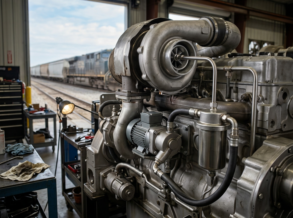
Operators ask this because downtime kills schedules and margins. Worn traction motor gears raise maintenance cost, cut tractive effort, and risk axle damage. Heat, poor lubrication, and shock loads accelerate wear. A proactive plan protects the diesel-electric locomotive drivetrain. It preserves torque transfer and safe gear ratio. It also safeguards the pinion gear and gearcase.
To keep locomotive gears reliable and performing well, focus on consistent inspection, monitoring, and timely replacements. The following key practices help minimize unplanned outages and extend component life:
- Reduce unplanned outages with scheduled gear inspections.
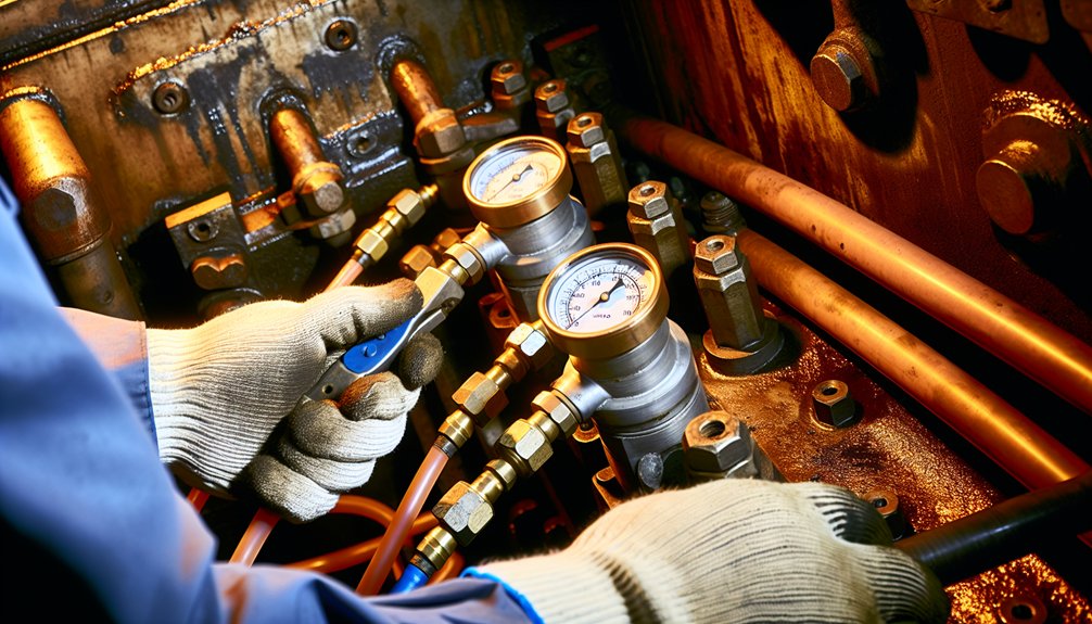
- Monitor lubricant condition and viscosity weekly.
- Trend vibration on each locomotive axle.
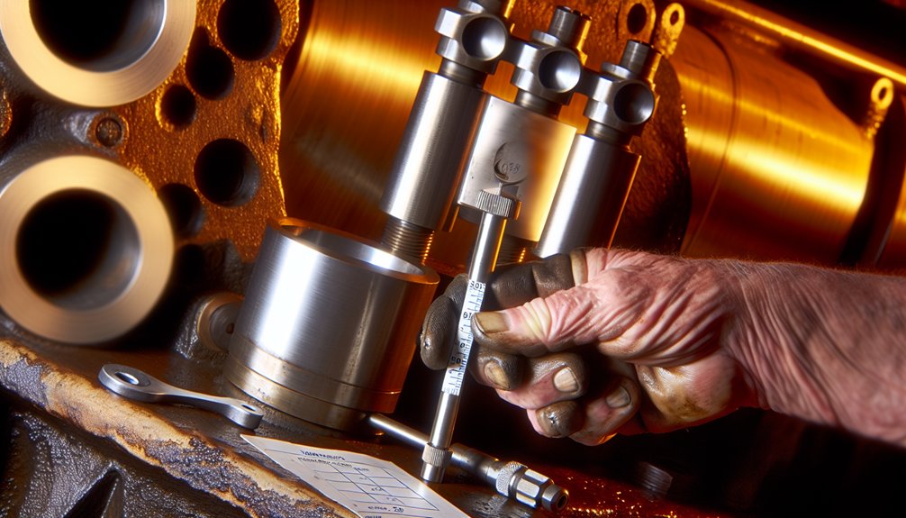
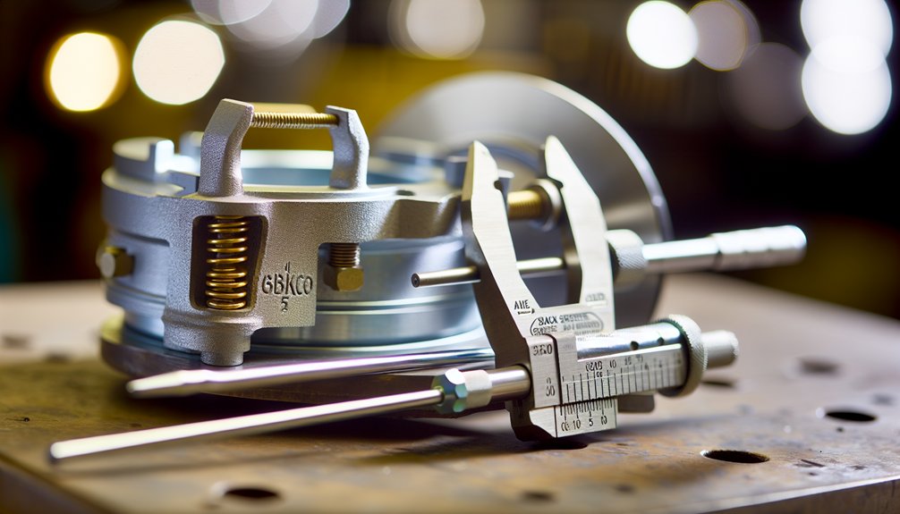
- Measure gear backlash and diameter tolerance each quarter.
- Borescope the gear case after heavy freight duty cycles.
- Replace pinion gear before pitting reaches critical depth.
- Align traction motor to axle after any truck work.
- Verify motor transition logic to limit shock loads.
- Use approved lubricants for the specific EMD gearcase.
- Keep a spare set for rapid change-out in the shop.
Regular replacement controls risk better than reactive fixes. EMD locomotive traction motor gears endure high torque spikes. They see cyclic loads from motor transition events and wheel-rail slip. As the gear teeth wear, contact stress rises and heat increases. That accelerates micropitting and scuffing. These faults spread to the pinion and the bull gear. The result is lost efficiency, noise, and rising current draw on the dc traction motor or ac traction motor. For commercial operators, that means higher fuel use and more yard time. Mikura International supports planned renewal with proven parts and guidance.
Common Issues with Traction Motor Gears

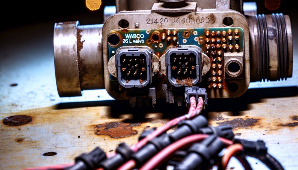
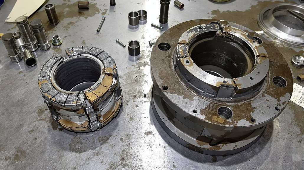
Traction motor gear trains face abrasive contaminants, lube starvation, and misalignment. Contamination enters the gear case when seals age. Poor lubricant selection reduces film strength at high load. Incorrect gear ratio selection for duty leads to chronic overload. Thermal cycling in freight locomotives promotes microcracks. Incorrect pinion fit on the armature shaft causes runout. In dc traction, commutation events can induce torque ripple. In ac traction, inverter control faults can spike torque. All of this concentrates stress at the pitch line. Over time, tooth profiles deviate from ideal involute geometry. That elevates vibration, heat, and noise, leading to traction motor failures.
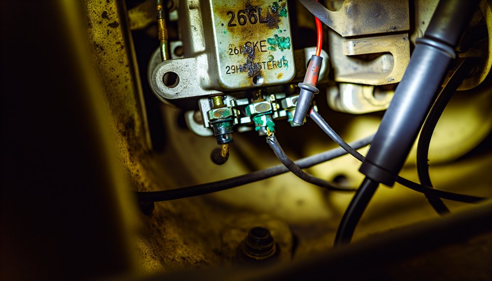
Identifying Traction Motor Failures
Early detection begins with condition-based monitoring. Several checks and observations help identify issues early and guide maintenance actions:
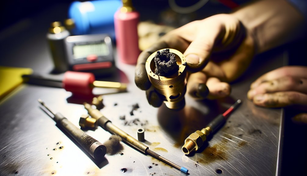
- Check oil debris with ferrography to find steel particles from the pinion gear.
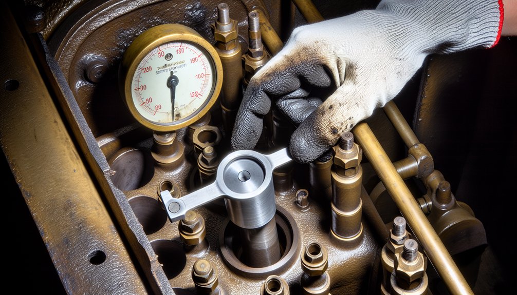
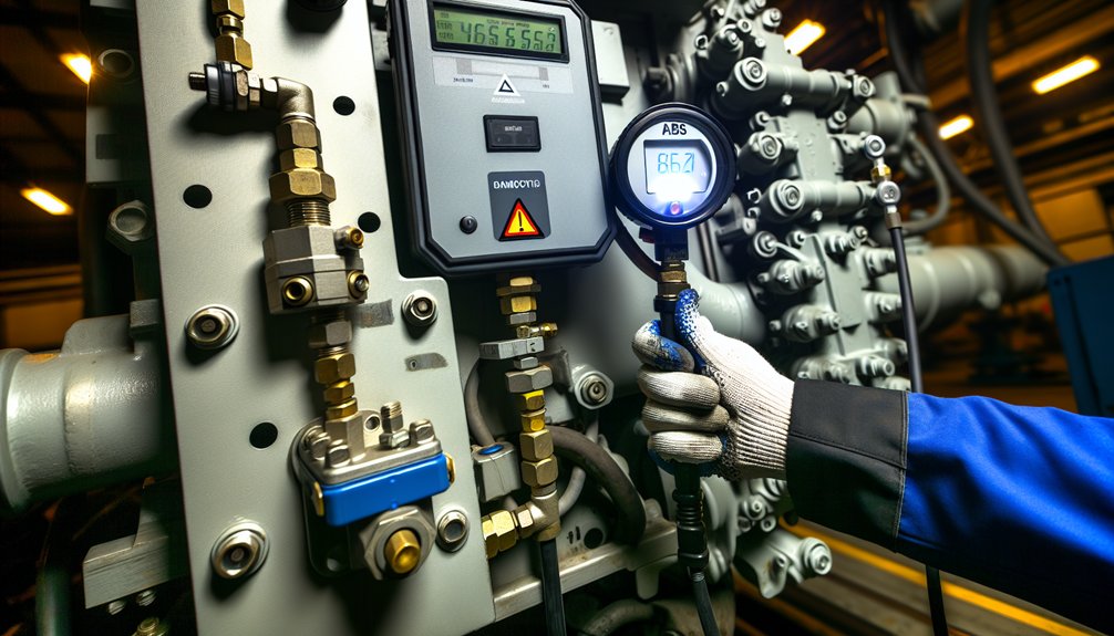
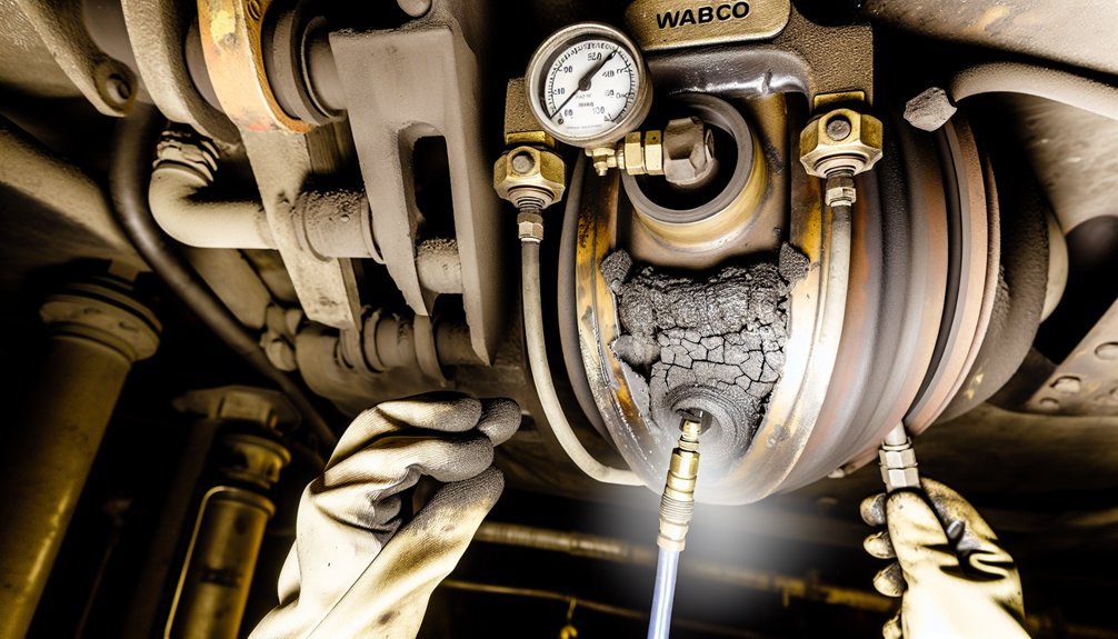
- Measure temperature rise in the gearcase under steady tractive effort.
- Watch for current imbalance across traction motors on one truck.
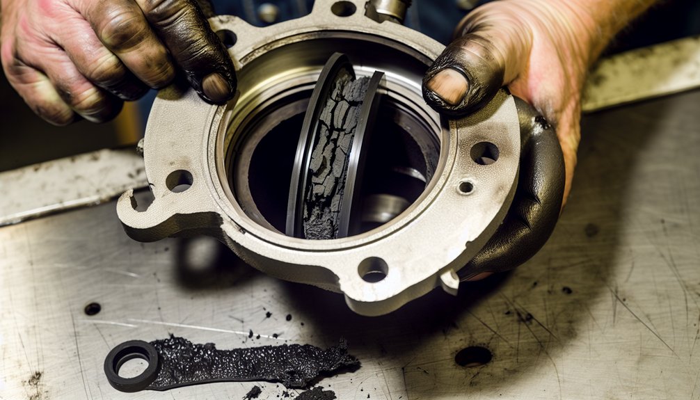
- Inspect tooth flanks for pitting, scuffing, or spalling.
- Verify backlash and contact pattern using dye.
- Listen for tonal harmonics that follow axle rotational speed.
- In dc traction systems, note rising armature current at constant load as a hint of friction growth.
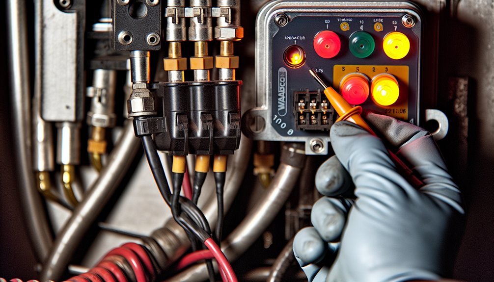
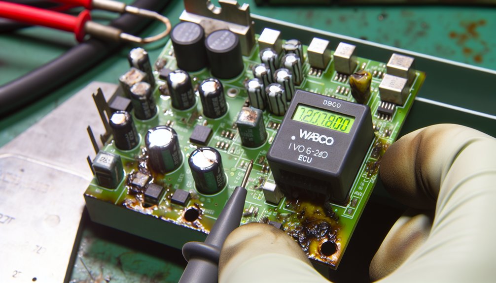
- In ac traction, review inverter fault logs for torque limiting events.
- If the locomotive transition sequence is rough, inspect for chipped teeth.
Rapid action prevents a cascading failure.
Impact of Worn Gears on Performance
Worn teeth reduce effective torque transfer to the locomotive axle. Slippage grows, so the control system chases setpoints. The prime mover burns more fuel to hold speed. Tractive effort falls, especially at low speed in heavy freight duty. Heat builds in the gearcase and lubricant oxidizes faster. The dc traction motor or induction motor in ac traction draws higher current. That loads the alternator and inverter, stressing components. Noise increases as the gear mesh loses its precision. The result is longer braking distances and slower acceleration. Maintenance cost rises from collateral damage to bearings, seals, and the axle seat. Planned replacement restores locomotive gearing efficiency.
Signs Your Pinion Gear Needs Replacement
Look for chipped leading edges on the pinion gear teeth. Check for pitting clusters at the pitch line. Excessive backlash beyond specification signals wear on diameter. Blueing on the tooth face shows heat from boundary lubrication. A milky lubricant indicates water ingress in the gear case. Vibration at a frequency tied to the pinion’s tooth count is another clue. If noise rises during motor transition, inspect the traction motor pinion gear immediately. Evidence of fretting at the armature shaft fit requires renewal. Any ge profile deviation that shifts load off the designed contact patch is reason to replace. Mikura International supplies matched pinion sets for EMD locomotives to reduce downtime.
Benefits of Regular Gear Replacement

Regular renewal prevents hidden losses. It restores clean torque transfer between the pinion and axle. It keeps lubricant temperatures stable and lowers current draw. Operators see fewer traction motor failures and smoother locomotive transition events. The diesel-electric locomotive runs cooler and pulls harder with less fuel. Shops avoid collateral damage to bearings and seals. Fleet managers gain predictable cycles and strong resale value. Mikura International supports planned intervals with matched locomotive gearing for EMD platforms.
Enhancing Efficiency and Performance
Fresh traction motor gear sets return the designed gear ratio and accurate contact pattern. That maximizes tractive effort at the rail and trims slip events. The dc traction motor or ac traction motor delivers torque without excess heat. Lower friction cuts amperage, easing the inverter and alternator. Stable lubrication films reduce micro-pitting across the tooth face. The prime mover holds speed with less throttle in heavy freight. Motor transition becomes smooth, protecting the armature and bearings. Accurate diameter and backlash restore quiet mesh. The result is faster acceleration, sustained grade performance, and fuel savings.
Reducing Maintenance Costs Over Time
Scheduled replacement limits cascading damage in the gearcase and gear case seals. It prevents chipped pinion teeth from scoring the bull gear and axle seat. Lower heat slows lubricant oxidation, extending drain intervals. Reduced vibration protects the dc traction motor windings and induction motor bearings. Shops spend less time on unscheduled tear downs and more on planned tasks. Inventory planning gets easier with known cycles for the traction motor pinion gear. Energy savings stack up as tractive effort improves and current draw falls. Across a fleet, the maintenance cost curve bends down. Mikura International helps standardize kits and timing for EMD fleets.
Improving Safety and Reliability
Healthy locomotive traction gears preserve predictable torque delivery to the locomotive axle. That shortens stopping distances and stabilizes handling under dynamic braking. Clean mesh reduces shock loads during locomotive transition and motor transition. It also lowers risk of sudden tooth failure that could lock an axle. Consistent lubrication flow in the gearcase prevents hotspots and smoke events. Control systems see fewer fault codes from the inverter and current limiters. Operators notice reduced noise and harmonics that mask hazards. Reliable gearing safeguards the armature, bearings, and seals, cutting traction motor failures. For mission-critical freight runs, reliability keeps schedules tight and crews safe.
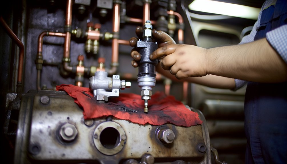
Replacement Process for EMD Locomotive Gears

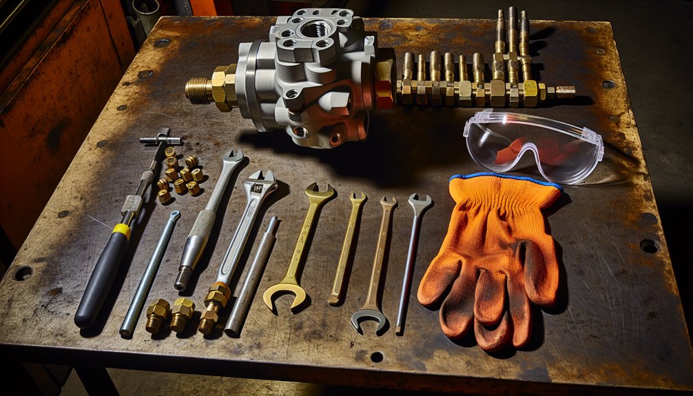
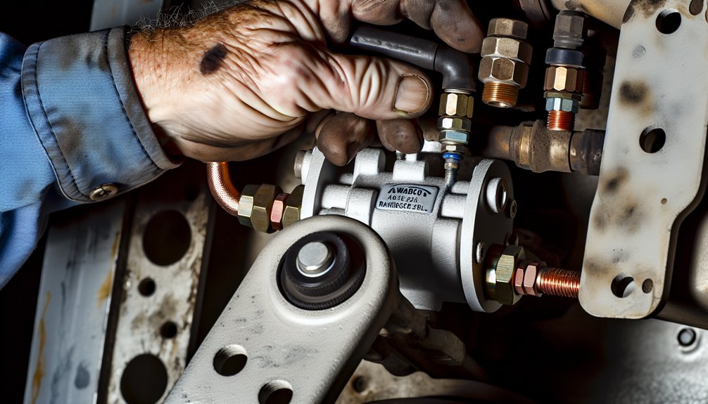
Replacing traction motor gear sets on an EMD diesel-electric locomotive needs control, precision, and clean workflow. The goal is to protect the axle, armature, and gearcase while restoring gear ratio and tractive effort. Shops should stage pinion gear, lubricant, seals, and fasteners before the locomotive enters the bay.
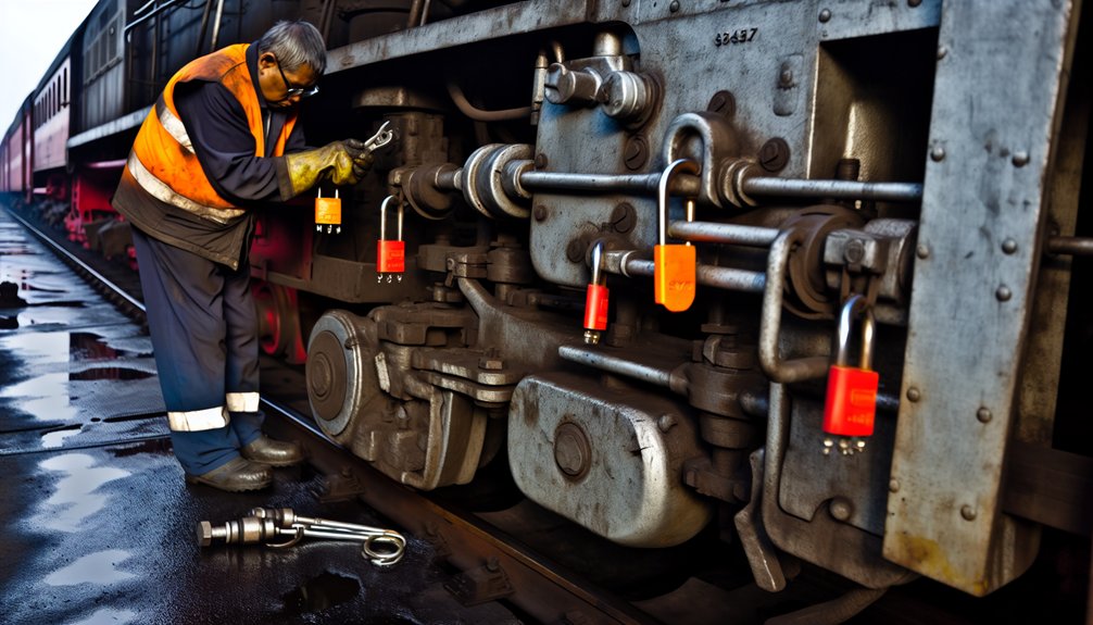
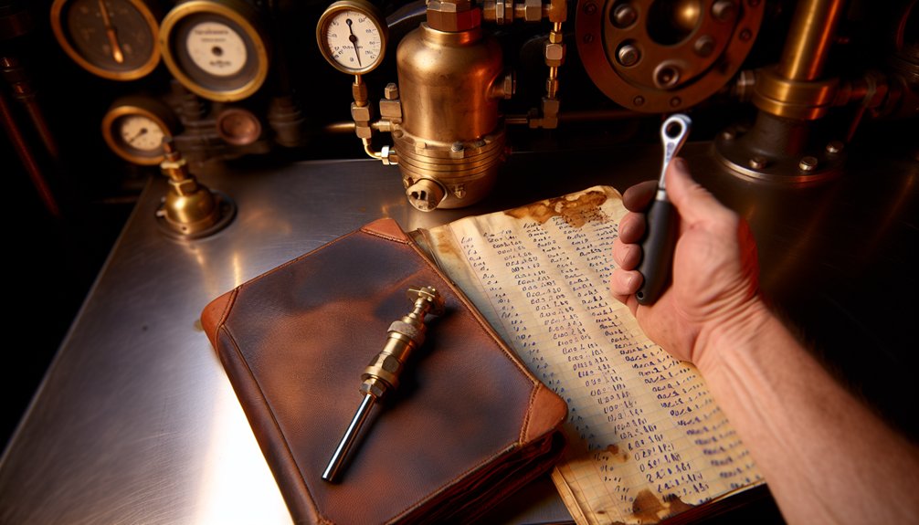
Use calibrated tools and fixtures that match the specified diameter and tolerance. Lockout-tagout the loco and isolate the inverter. Support the traction motor to avoid strain at the locomotive axle seat. Verify dc traction or ac traction configuration to plan motor transition tests. Keep contamination out of the gear case with strict covers and lint-free practices. Record every measurement to trend maintenance cost and reliability.
Steps to Replace Traction Motor Gears
To replace and verify the traction motor pinion and gear mesh on a locomotive, follow these steps in sequence:
- Begin with safety isolation and wheel chocking for the locomotive.
- Drain the gearcase and sample lubricant for debris trending.
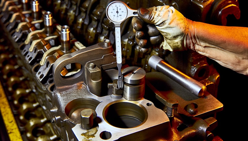
- Remove the gear case cover and inspect the traction motor gear mesh.
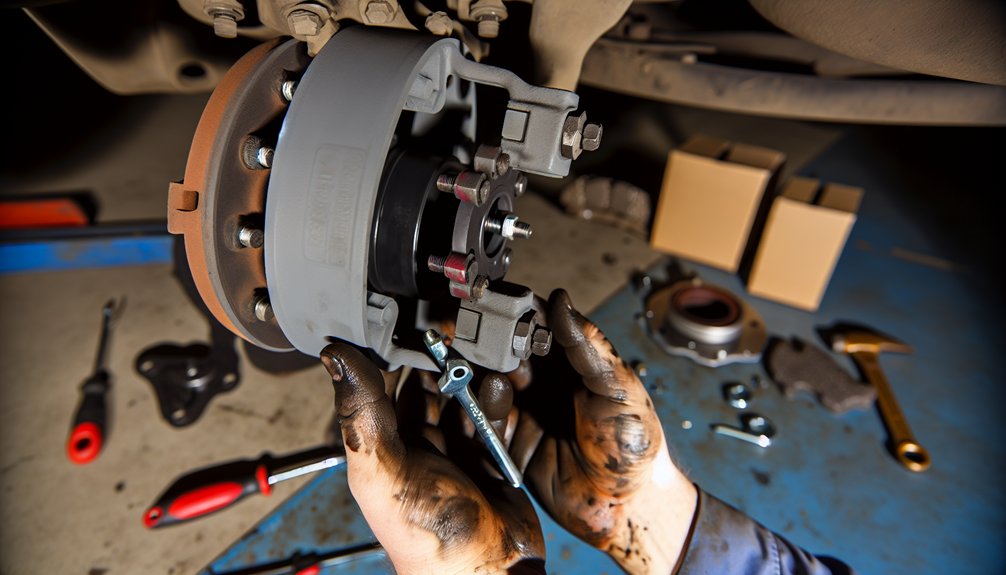
- Support the traction motor, then decouple it from the axle.
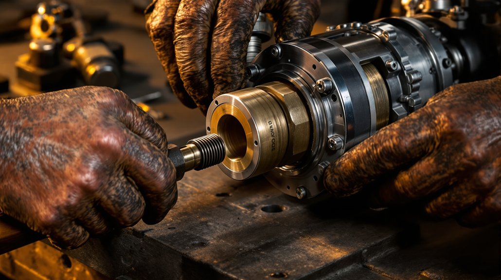
- Pull the worn pinion using the approved armature shaft puller.
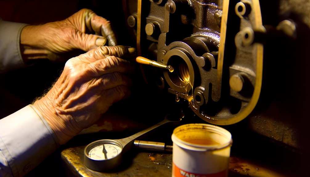
- Heat the new pinion gear as specified and shrink-fit to the armature with target interference.
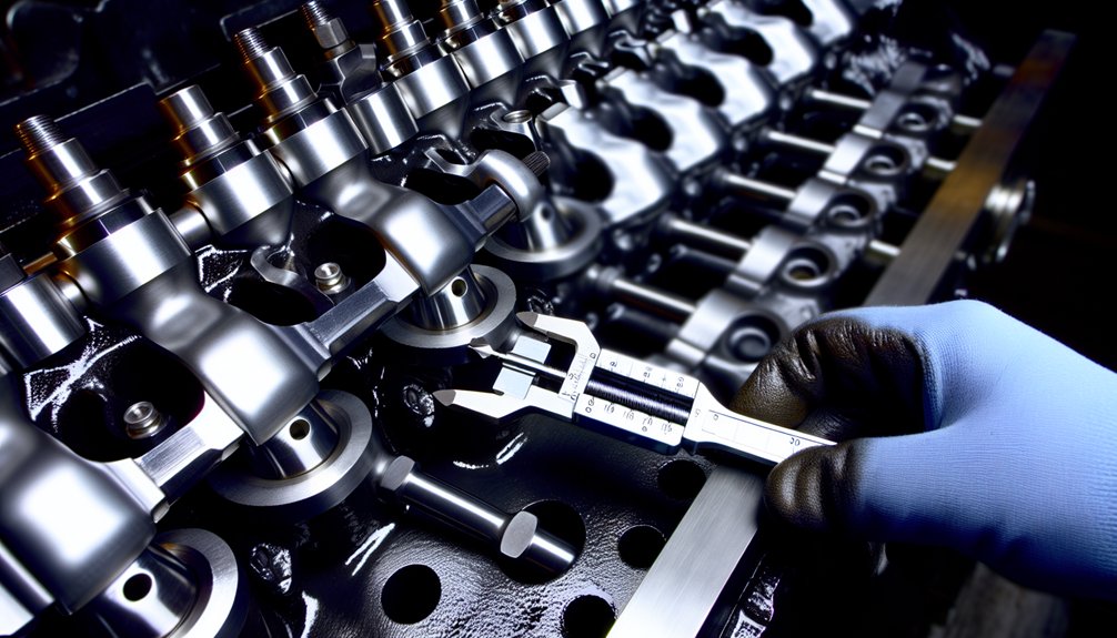
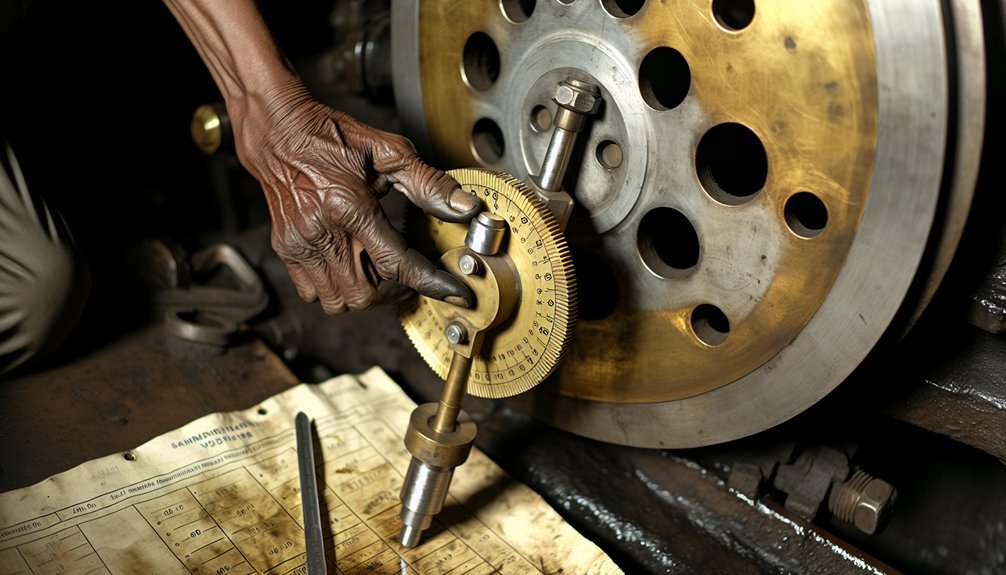
- Mount the bull gear if required, checking diameter and runout on the locomotive axle.
- Blue the teeth and verify contact pattern across the face width.
- Set backlash to EMD spec for the chosen gear ratio.
- Reassemble the gear case, refill with approved lubricant, and run a slow-roll test.
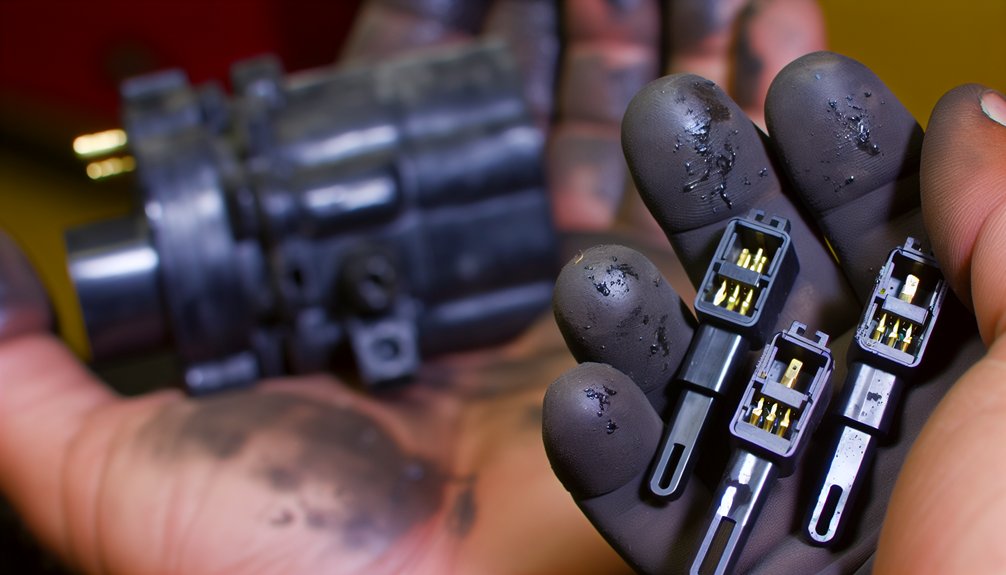
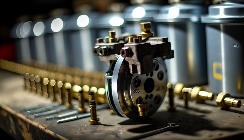
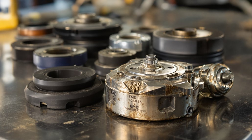
Choosing the Right Replacement Parts
Select EMD-compatible gear sets matched to duty cycle and traction type. Confirm pinion gear tooth count and gear ratio for planned freight grades and speeds. Validate bore diameter, spline or shrink-fit interface, and surface finish for the armature. For dc traction motor units, ensure metallurgy resists scuffing under ripple torque. For ac traction motor units, prioritize tooth profile accuracy for inverter-driven torque steps. Specify seals and gaskets rated for the gearcase temperature band. Choose lubricant with the correct viscosity, EP package, and compatibility with approved gear case materials. Mikura International provides matched locomotive gearing kits and documentation to cut installation time and reduce traction motor failures.
Expert Tips for a Smooth Transition
Stage tools, fixtures, and parts near the loco to compress downtime on freight locomotives and switcher units. Measure twice: record seating depth, backlash, and contact pattern before final torque. Maintain strict cleanliness inside the gear case during lubrication and sealing. After assembly, perform a controlled motor transition test to check noise and tonal harmonics. Use ac traction inverter diagnostics or dc traction current traces to verify smooth torque steps. Recheck fasteners after heat soak and a short load cycle. Trend oil debris after the first 24 hours to catch early seating wear. Calibrate tractive effort on a dynamometer when available. This discipline stabilizes torque transfer and lowers long-term maintenance cost.
Best Practices
Summarizing the Importance of Regular Replacements
Regular replacement protects tractive effort and controls maintenance cost. The locomotive axle, armature, and pinion gear stay within tolerance. Stable gear ratio preserves torque delivery under heavy freight. Consistent lubrication reduces heat and noise in the gearcase. Scheduled renewal cuts traction motor failures in both dc traction and ac traction fleets. It also eases inverter stress and smooths motor transition during locomotive transition. Efficiency improves as the prime mover avoids over-fueling and current draw falls. This discipline keeps the loco reliable, protects the gear case seals, and extends lubricant life across demanding freight locomotives.
Actionable Advice for Locomotive Operators
Set inspection intervals by duty cycle and environment. Trend backlash, contact pattern, and diameter on every loco truck. Sample lubricant each month and watch viscosity, water, and ferrous count. Validate inverter logs after motor transition events in ac traction systems. In dc traction units, compare armature current between axles for imbalance. Replace the pinion at defined pitting limits, not at failure. Keep a calibrated puller, heaters, and gauges staged for rapid turnaround. Standardize approved lubricants and storage to prevent contamination. Verify gear ratio against route grades to protect torque margins. Mikura International can supply matched EMD locomotive gearing kits and technical bulletins to streamline execution.
When to Consult Professionals
Engage experts for abnormal tooth mesh harmonics or shifted contact bands. Call in support if contact bands shift off the designed flank after adjustment. Seek help when repeated lubricant oxidation occurs despite correct viscosity and flow. Bring professionals if the loco shows recurring inverter torque limiting under steady load. In dc traction, consult when armature current rises at constant tractive effort. If runout at the locomotive axle or armature exceeds spec diameter tolerance, stop and assess. Escalate after any chipped tooth, blueing, or abnormal wear in the gear case. For route changes that alter freight grades, confirm gear ratio selection. Mikura International provides field guidance, parts validation, and failure analysis for EMD platforms.