Oil Specifications and Maintenance Guide for Locomotive Engine Bearing

Oil Specifications and Maintenance Guide for Locomotive Engine Bearing

This guide provides a comprehensive overview of oil specifications and maintenance practices critical for ensuring the longevity and optimal performance of locomotive engine bearings. Selecting the right oil and adhering to a strict maintenance schedule are crucial steps in preventing premature wear and costly repairs.

Understanding Locomotive Engine Bearings

Understanding Locomotive Engine Bearings

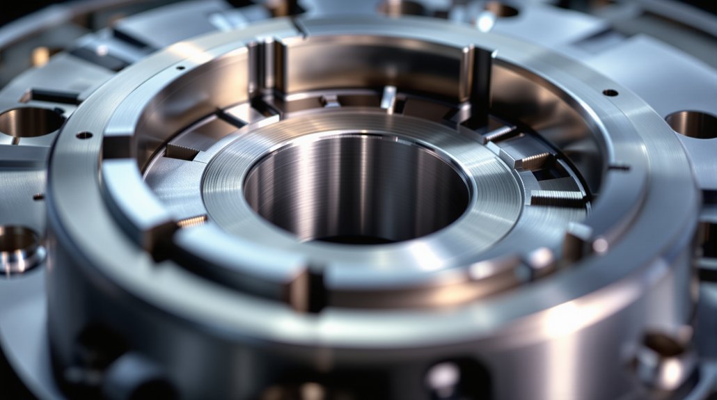
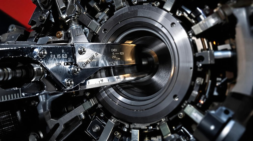
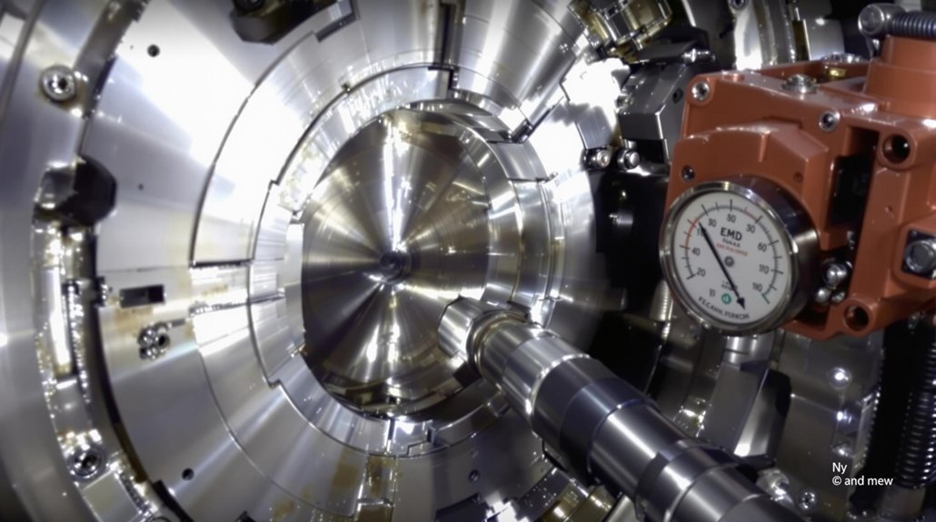
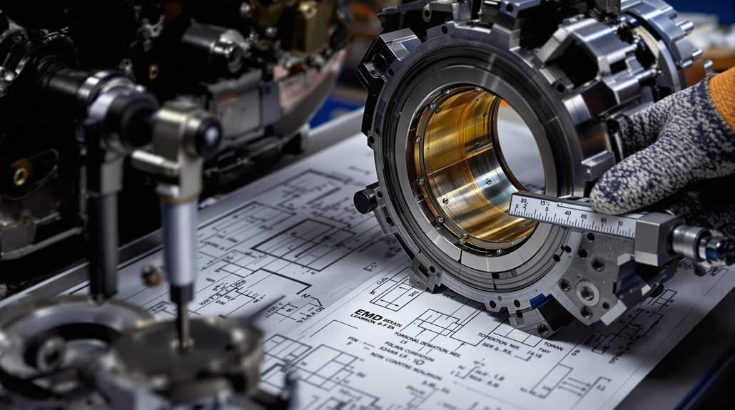
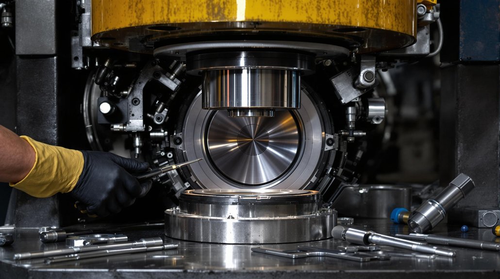
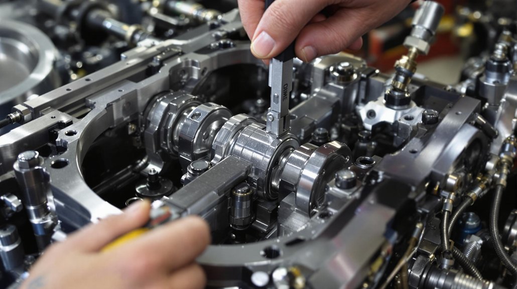
Locomotive engine bearings are essential components that minimize friction between moving parts, allowing for smooth and efficient operation. Understanding the types, functions, and common issues associated with these bearings is crucial for effective maintenance and ensuring the longevity of locomotive and marine engine performance. Selecting the appropriate lubricant is paramount for optimal operation.

Types of Engine Bearings

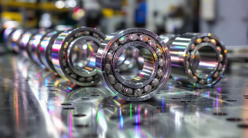
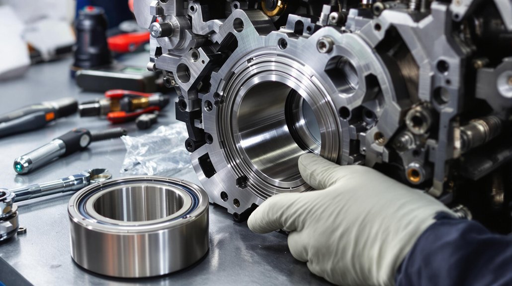
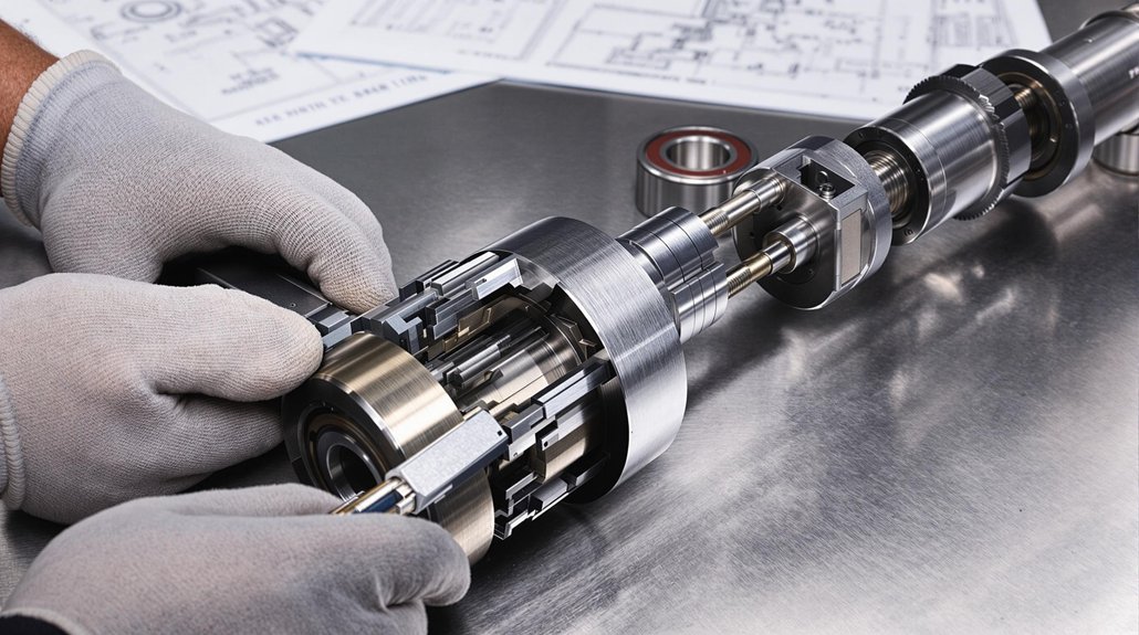
Various types of engine bearings are utilized in locomotives and marine vessels, each designed to withstand specific loads and operating conditions. These include plain bearings, roller bearings, and ball bearings. Each type of bearing has unique characteristics. Understanding these differences is important for selecting the appropriate lubricant to ensure premium performance and long life in demanding locomotive and marine engine applications.

Function and Importance of Bearings

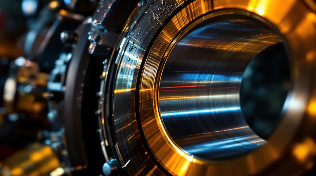
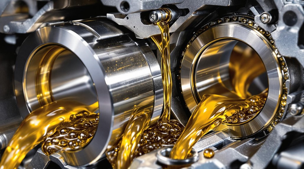
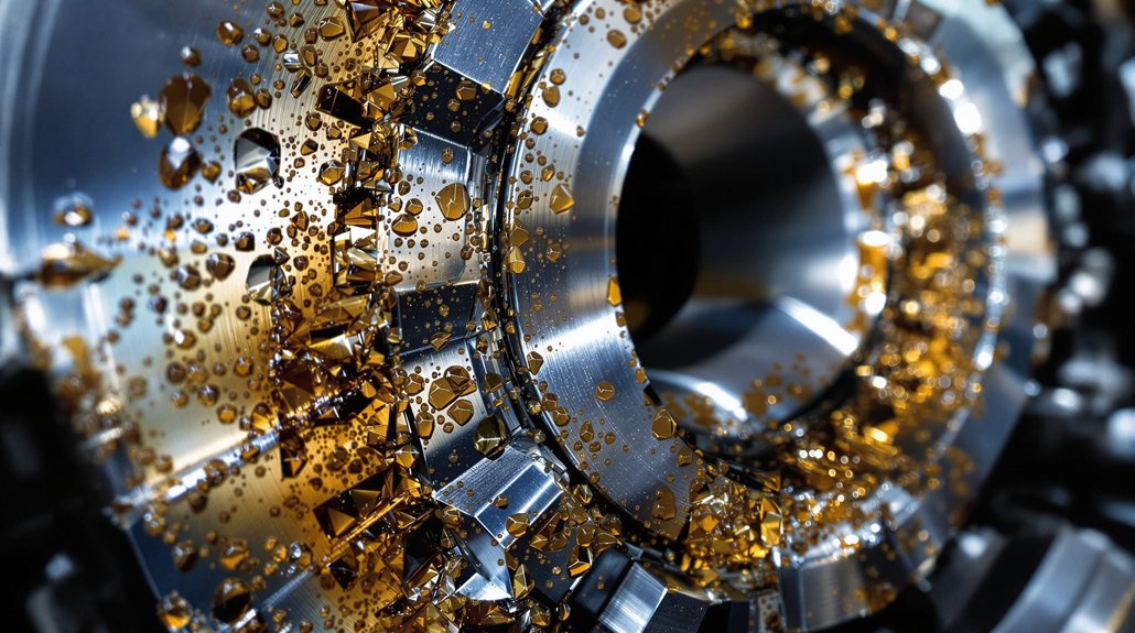
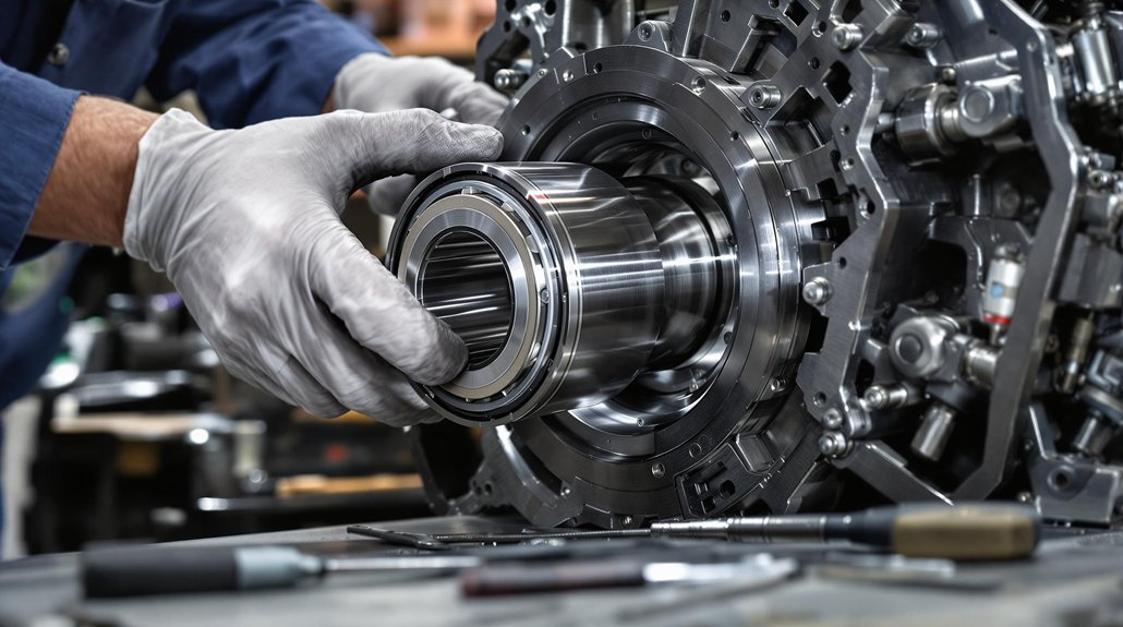
The primary function of bearings is to reduce friction between moving surfaces within the locomotive engine, enabling smooth and efficient power transfer. Bearings support the crankshaft, connecting rods, and other critical components, allowing them to rotate freely. Superior bearing function ensures optimal engine performance, minimizes wear and tear, and contributes to the overall reliability of the locomotive and marine engine.

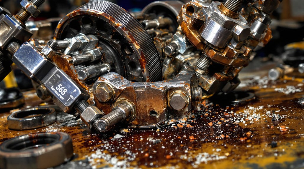
Common Issues with Locomotive Bearings

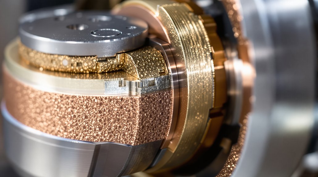
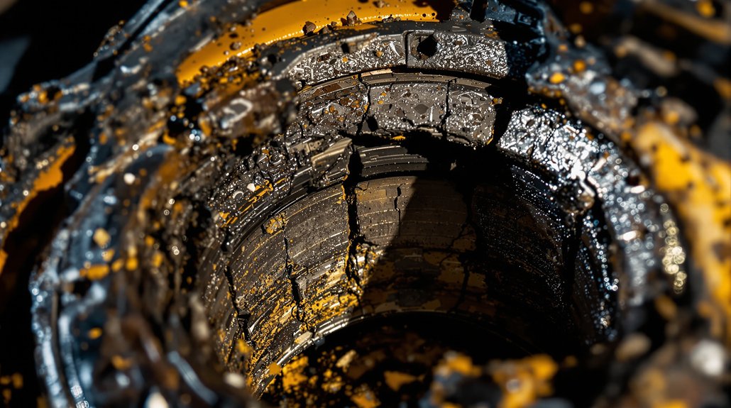
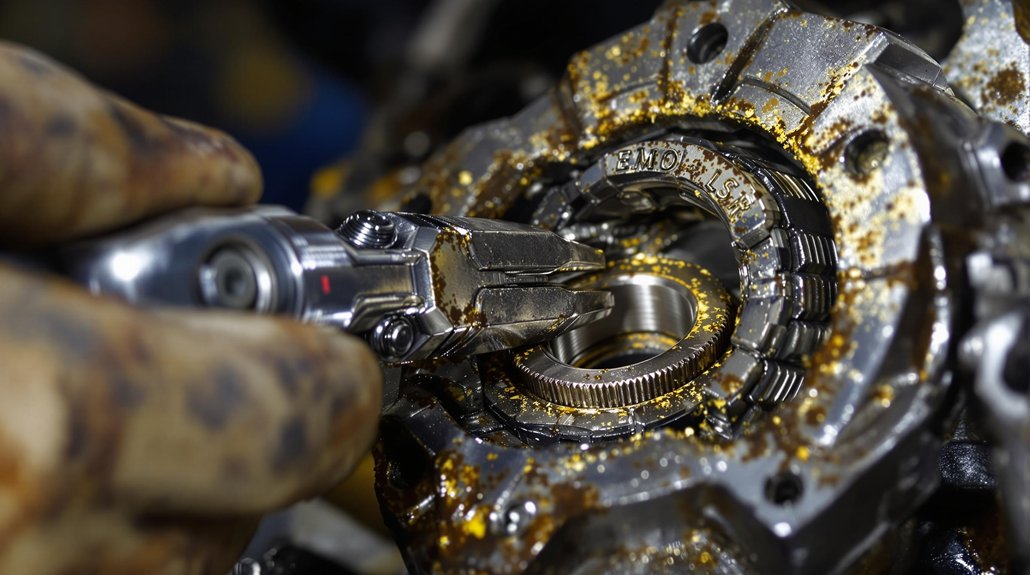
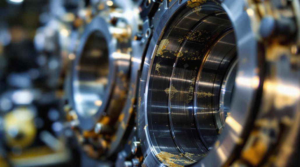
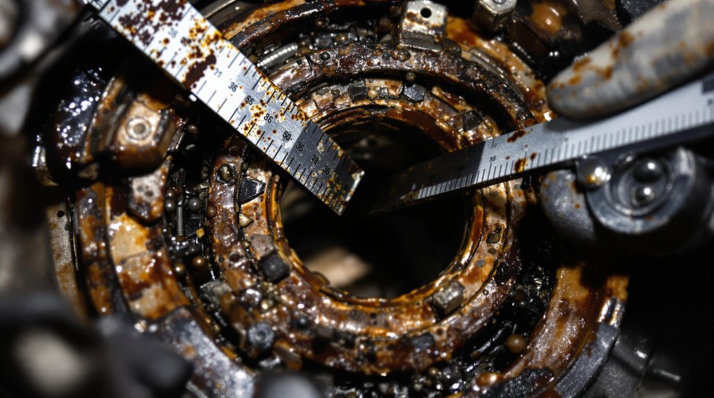
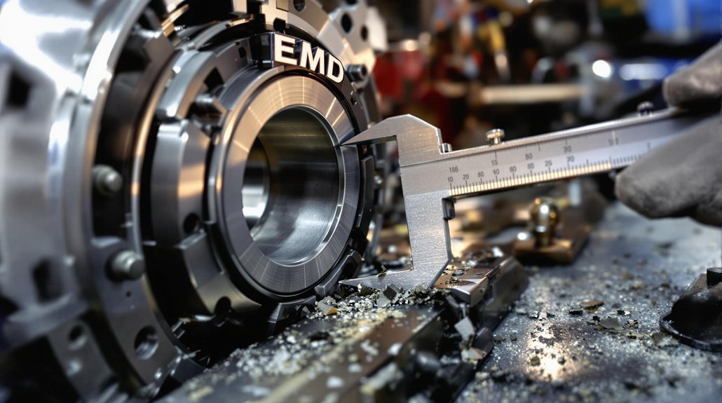
Locomotive bearings are susceptible to various issues that can compromise their performance and lifespan. These include wear, corrosion, fatigue, and contamination. Wear can occur due to inadequate lubrication or excessive loads, while corrosion can result from moisture or chemical exposure. Regular inspections and adherence to strict oil standards help prevent these issues and ensure the reliable operation of locomotive engine bearings. Mikura International understands these challenges and can provide the necessary spare parts.

Oil Specifications for Locomotive Engines

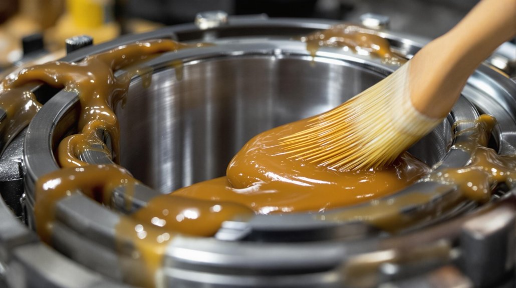
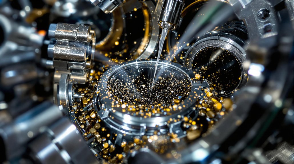
Selecting the correct locomotive oil is critical for maintaining optimal performance and extending the life of engine bearings in both locomotive and marine vessels. The right oil not only lubricates but also cools, cleans, and protects engine components from corrosion and wear. Using substandard oil can lead to premature bearing failure, reduced engine efficiency, and costly repairs. Therefore, understanding oil specifications and choosing a premium product is essential.

Types of Oils Used in Locomotive Engines

Different types of oils are used in locomotive engines. These oils can be categorized as follows:

  • Mineral oils, which are derived from crude oil and are suitable for many applications.
  • Synthetic oils, engineered to provide superior performance under extreme conditions.
  • Semi-synthetic blends, offering a balance between cost and performance.

The selection depends on the engine type, operating conditions, and manufacturer recommendations to ensure optimum locomotive operation.

Viscosity Ratings and Their Importance

Viscosity is a measure of an oil’s resistance to flow, and it is crucial for maintaining proper lubrication in locomotive engines. The viscosity rating indicates how well the oil will perform at different temperatures. Multi-grade oils, such as SAE 15W-40, are commonly used because they provide adequate lubrication across a wide temperature range. Choosing the correct viscosity grade ensures that the oil maintains a sufficient film thickness between moving parts, preventing wear and tear on critical engine components.

API and SAE Standards for Locomotive Oil

The American Petroleum Institute (API) and the Society of Automotive Engineers (SAE) set standards for oil performance. These standards cover different aspects of oil quality and suitability, including:

  • API standards, which classify oils based on their suitability for different engine types and operating conditions.
  • SAE standards, which define viscosity grades.

Locomotive oils must meet specific API and SAE standards to ensure they provide adequate protection and performance. Compliance with these standards guarantees that the oil has undergone rigorous testing and meets the necessary requirements for marine vessels and locomotive applications.

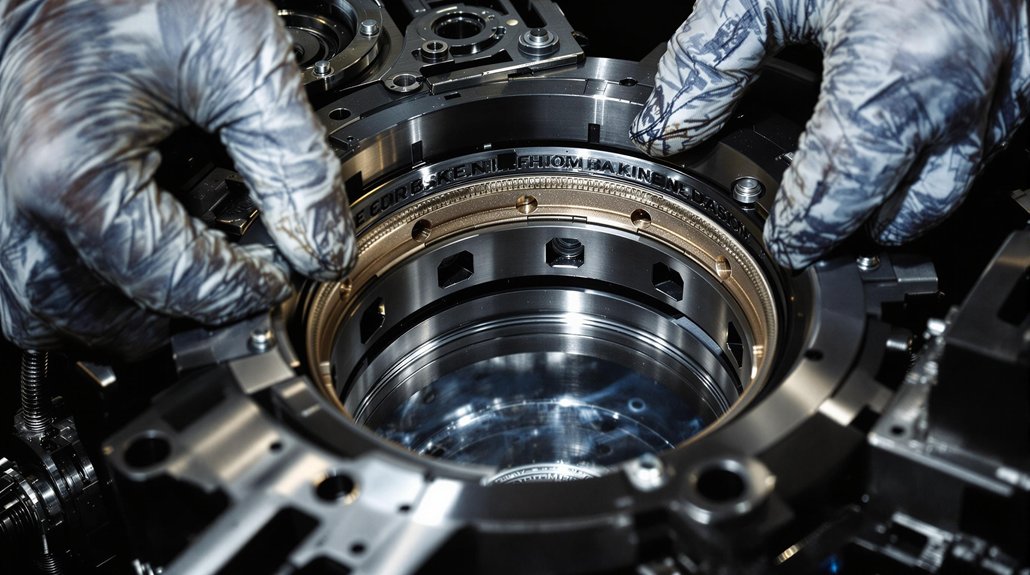
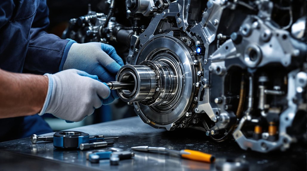
Maintenance Practices for Engine Bearings

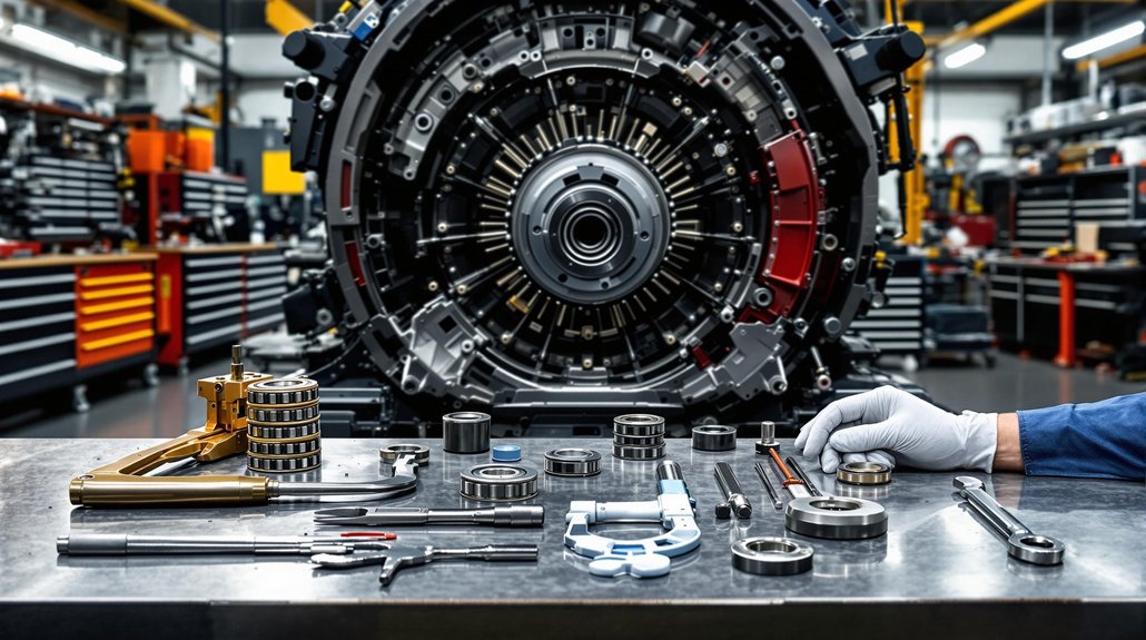
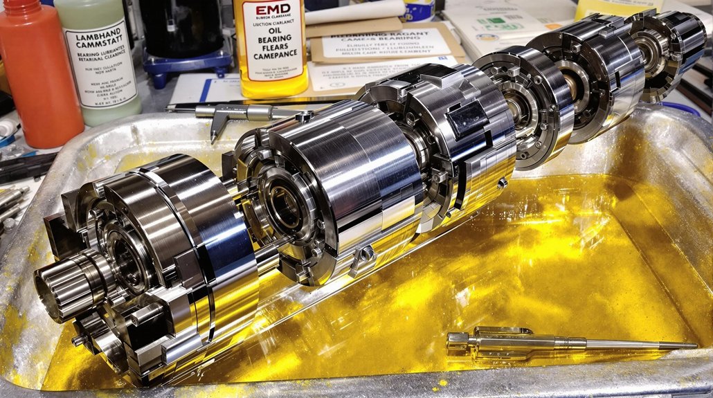
Effective maintenance practices are vital for prolonging the life of engine bearings and maintaining the performance of locomotive engines. Regular inspection, proper lubrication, and timely oil changes are essential steps in preventing premature bearing failure. By adhering to a strict maintenance schedule and utilizing advanced oil analysis techniques, operators can ensure the reliable operation of their locomotive fleets. Mikura International is committed to helping you ensure optimal locomotive performance.

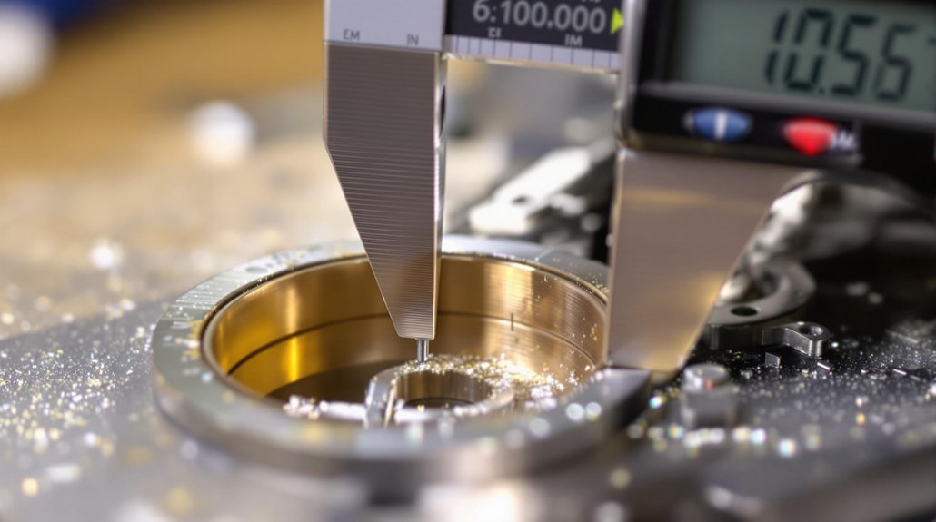
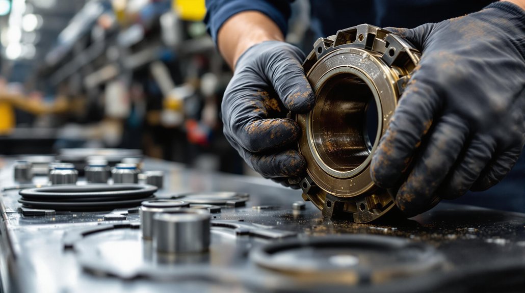
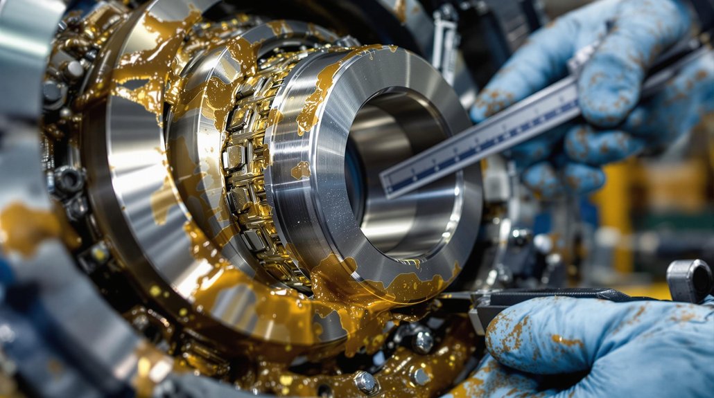
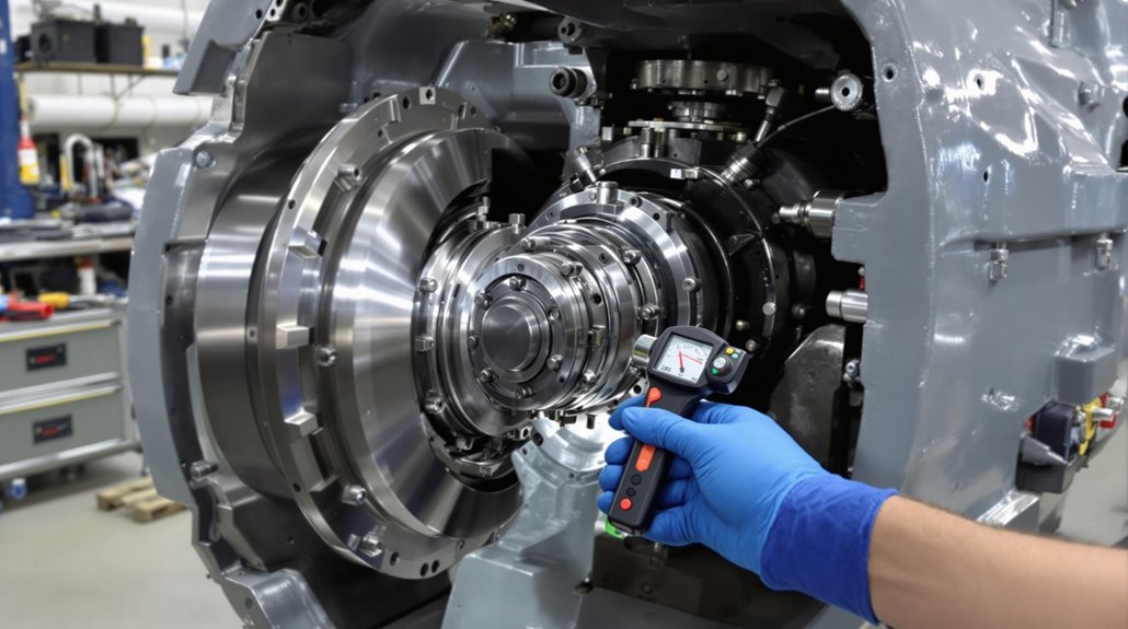
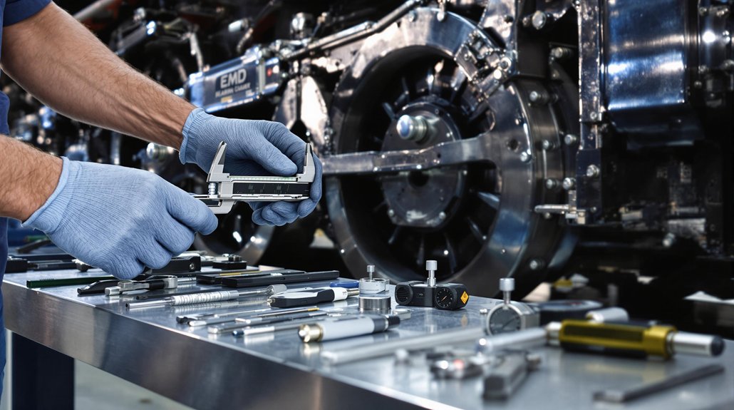
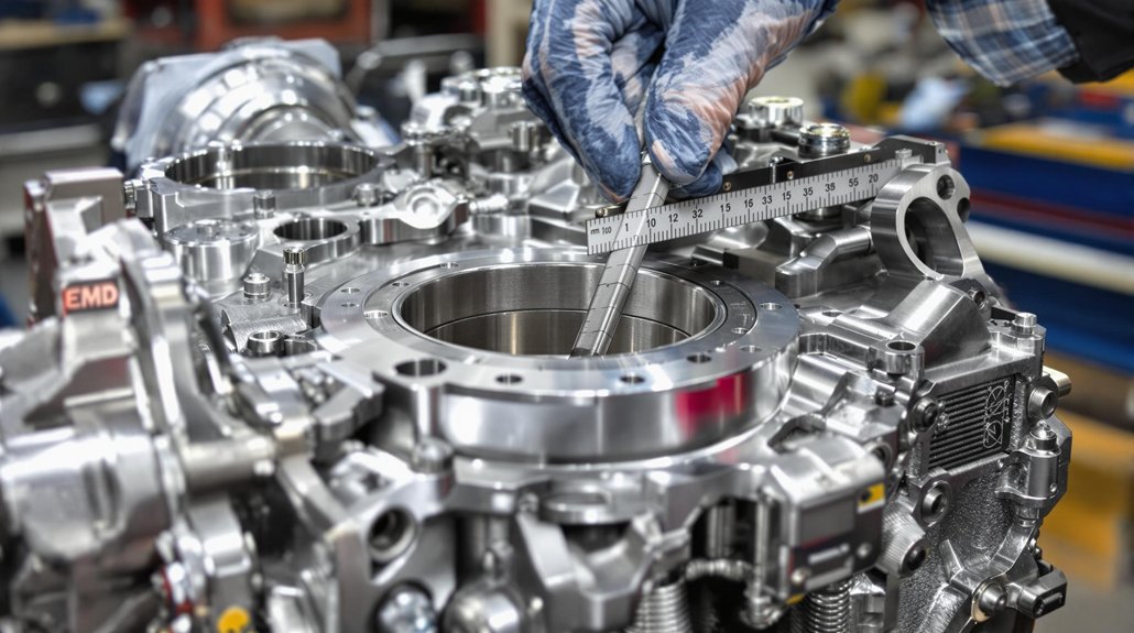
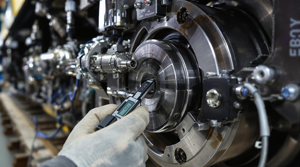
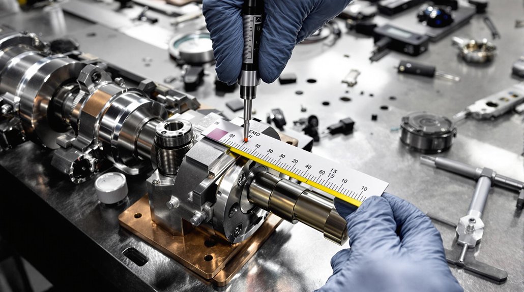
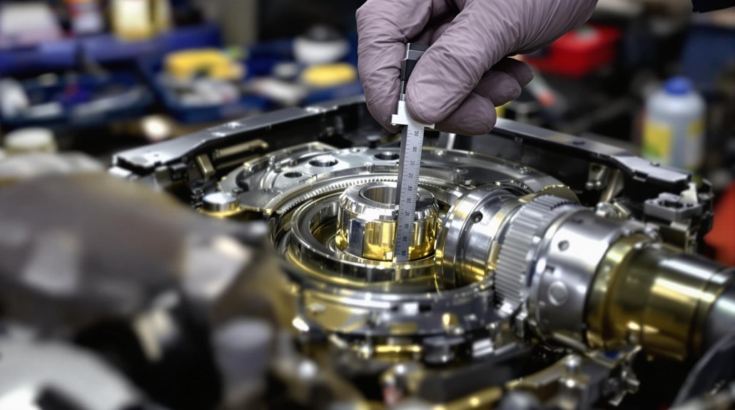
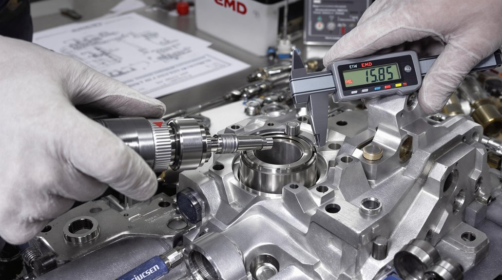
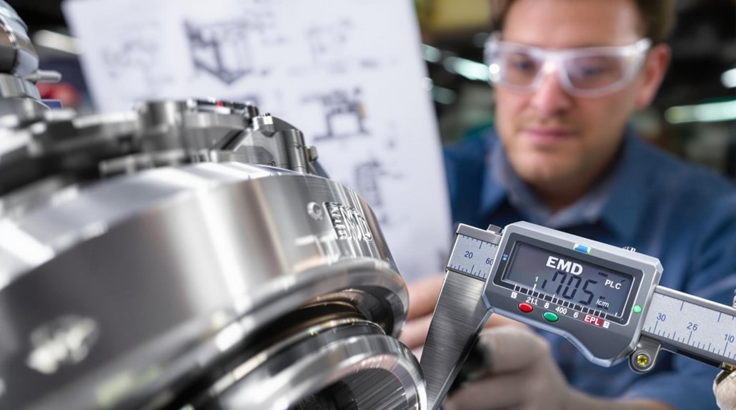
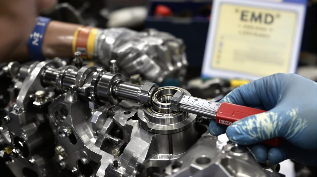
Regular Inspection and Monitoring

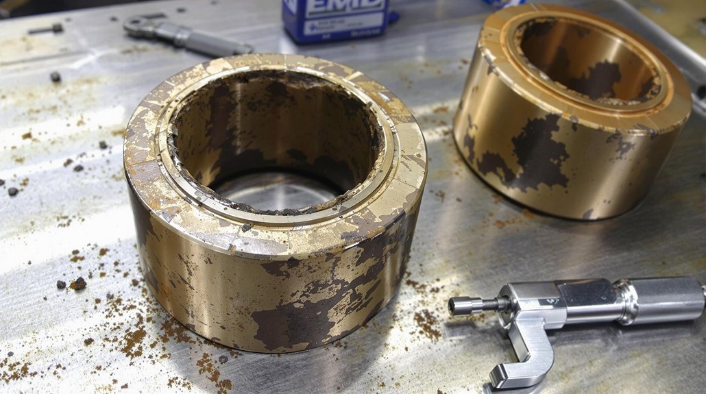
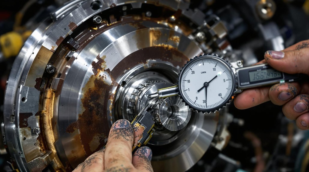
Regular inspection and monitoring of engine bearings are essential for identifying potential issues before they lead to catastrophic failures. Visual inspections can reveal signs of wear, corrosion, or contamination. Monitoring oil pressure and temperature can also indicate the health of the bearings. Implementing a proactive inspection program allows for early detection of problems, enabling timely intervention and preventing costly downtime.

Oil Change Intervals and Best Practices

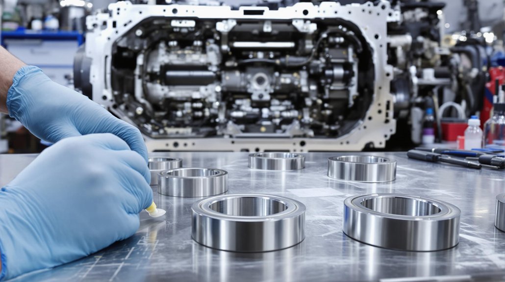
Adhering to recommended oil change intervals is critical for maintaining the performance of engine bearings. Over time, oil degrades and becomes contaminated with dirt, debris, and combustion byproducts, reducing its ability to lubricate and protect engine components. Following the manufacturer’s recommendations for oil change intervals and using high-quality filters can ensure that the oil remains clean and effective, extending the life of the bearings and the engine. These best practices help provide superior maintenance.

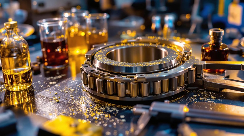
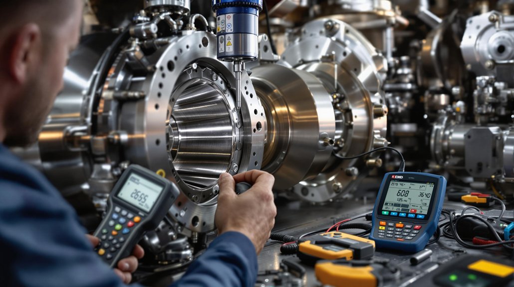
Utilizing Advanced Oil Analysis Techniques

Advanced oil analysis techniques can provide valuable insights into the condition of the oil and the engine bearings. Spectrometric analysis can identify the presence of wear metals, contaminants, and additives in the oil. Viscosity measurements can indicate whether the oil has thinned or thickened, while acid number testing can assess its level of degradation. By regularly analyzing oil samples, operators can detect potential problems early and take corrective action, preventing costly repairs and downtime. Doing so helps to ensure future reliability and long life.

Best Oils for Locomotive Engine Bearings

Best Oils for Locomotive Engine Bearings

Recommended Oil Brands for Locomotive Bearings

Selecting the right oil brand is crucial for the optimal performance of locomotive engine bearings. While various brands claim to provide superior lubrication, it’s important to focus on those that meet or exceed industry standards. Look for brands known for their rigorous testing, quality control, and specialized formulations designed specifically for heavy-duty applications. Consider brands that have a proven track record, as these are more likely to ensure the longevity and reliability of your bearings.

Choosing Oil Based on Operating Conditions

The selection of locomotive oil should also be influenced by the specific operating conditions of the engine. Factors such as ambient temperature, load, and duty cycle can all affect oil performance. In high-temperature environments, synthetic oils may be preferable due to their superior thermal stability. For engines operating under heavy loads, consider oils with enhanced anti-wear additives to provide additional protection. Matching the oil to the operating conditions will ensure optimal lubrication and prolong the life of engine bearings and associated components.

Impact of Quality Oil on Bearing Longevity

The quality of oil used in locomotive engines has a direct impact on the longevity of bearings. High-quality oils contain additives that reduce friction, prevent corrosion, and dissipate heat, all of which contribute to extending bearing life. Conversely, using low-quality or unsuitable oil can lead to premature wear, increased friction, and potential bearing failure. Investing in a premium oil that meets or exceeds the manufacturer’s specifications is a cost-effective way to ensure the reliable performance and longevity of your locomotive engine bearings.

Expert Insights on Locomotive Engine Maintenance

Common Mistakes to Avoid

Several common mistakes can compromise the effectiveness of locomotive engine maintenance, including neglecting regular inspections, using the wrong type of oil, and failing to adhere to recommended oil change intervals. Overlooking these seemingly minor details can lead to significant performance issues and costly repairs. Another frequent error is ignoring early warning signs of bearing distress, such as unusual noises or elevated temperatures. Avoiding these mistakes is essential for ensure optimal locomotive engine performance and extending the life of critical components.

Tips from Industry Experts

Industry experts emphasize the importance of proactive maintenance strategies to ensure the longevity and reliability of locomotive engines. One key tip is to conduct regular oil analysis to monitor its condition and identify potential problems early on. Experts also recommend using high-quality filters to remove contaminants and prevent wear on bearings and other critical components. Furthermore, they advise closely following the manufacturer’s recommendations for lubrication and maintenance schedules to provide the best possible performance and protection.

Future Trends in Locomotive Engine Oil Technology

The future of locomotive engine oil technology is focused on developing more sustainable and high-performance lubricants. Researchers are exploring the use of bio-based oils and advanced additives to reduce environmental impact and improve engine efficiency. Nanotechnology is also being applied to create oils with superior friction-reducing and wear-resistant properties. These advancements promise to provide enhanced protection for locomotive bearings, extending their lifespan and reducing maintenance costs. Mikura International stays abreast of these developments to ensure we provide the best possible parts and advice.

FAQ

Q: What are the key oil specifications for locomotive engine bearings?

A: The key oil specifications for locomotive engine bearings typically include viscosity grade, detergent and dispersant levels, and anti-wear additives. It is essential to follow the manufacturer’s guidelines to ensure optimal performance and longevity of the bearings.

Q: How does oil viscosity affect locomotive engine performance?

A: Oil viscosity plays a crucial role in the lubrication of locomotive engine bearings. The right viscosity ensures that the oil can effectively reduce friction while maintaining a proper film thickness under varying temperature and load conditions, similar to requirements in a marine engine.

Q: What maintenance practices are recommended for locomotive engine bearings?

A: Recommended maintenance practices include regular oil changes, monitoring oil levels, checking for contamination, and inspecting bearing surfaces for wear. Following these practices helps ensure the efficient operation of the bearings, akin to maintenance protocols in marine engines.

Q: How often should oil be changed in locomotive engine bearings?

A: The frequency of oil changes depends on operating conditions and the type of oil used. Generally, it is recommended to change the oil every 500 to 1,000 hours of operation, but this may vary based on specific locomotive and environmental factors.

Q: What are the signs of oil degradation in locomotive engine bearings?

A: Signs of oil degradation include increased engine temperature, unusual noises from the bearings, visible discoloration of the oil, and the presence of metal particles in the oil. Regular oil analysis can help detect these issues early.

Q: Can marine engine oil be used in locomotive engine bearings?

A: While some marine engine oils may meet the viscosity and performance requirements for locomotive engine bearings, it is essential to consult the manufacturer’s specifications before using marine oil to ensure compatibility and efficacy.

Q: What additives are important in oil for locomotive engine bearings?

A: Important additives for oil used in locomotive engine bearings include anti-wear agents, detergents, dispersants, and antioxidants. These additives help maintain oil performance and protect against wear and corrosion, similar to the needs in marine engine applications.

Q: How does temperature affect oil performance in locomotive engines?

A: Temperature significantly impacts oil performance in locomotive engines. High temperatures can lead to oil thinning and reduced lubrication effectiveness, while low temperatures can cause the oil to become too viscous. Maintaining optimal operating temperatures is critical for bearing longevity.

Q: What role does oil filtration play in locomotive engine bearing maintenance?

A: Oil filtration is crucial in maintaining clean oil in locomotive engine bearings. Effective filtration helps remove contaminants that can cause wear and damage to the bearings, thus prolonging their life and enhancing engine performance.

10 Locomotive Camshaft Bearing Alloy Specifications You Need

10 Locomotive Camshaft Bearing Alloy Specifications You Need

You’ll need aluminum alloys with 200-300 MPa fatigue resistance, copper-based alloys offering 152-227 W/m·K thermal conductivity, and steel-backed tri-metal constructions for EMD applications. Critical specifications include 0.001-0.004″ clearances, babbitt compositions with 88-90% tin content, and thermal expansion coefficients matching camshaft materials. Bi-metal configurations provide enhanced durability over tri-metal overlays, while copper-HCP delivers 98% IACS electrical conductivity correlating with superior thermal transfer. These foundational specifications form the framework for thorough locomotive bearing selection criteria.

Key Takeaways

  • Aluminum alloys require 130-227 W/m·K thermal conductivity with 6061-T6 grade offering 152-154 W/m·K for optimal heat dissipation.
  • Copper-based alloys must maintain 98% IACS electrical conductivity with phosphorous content between 0.002-0.007% for enhanced thermal transfer.
  • Tri-metal construction needs steel backing, copper intermediate layer, and 0.0005-0.0008″ lead-based overlay for high-load applications.
  • Fatigue resistance specifications require 200-300 MPa endurance limits under 10^4 to 10^7 cycle testing protocols.
  • Operating clearances must be 0.0015-0.002 times bearing diameter with EMD minimum recommendation of 0.0025 inches.

Aluminum Alloy Fatigue Strength Requirements for EMD Locomotive Applications

aluminum bearing fatigue requirements

When designing camshaft bearing systems for EMD locomotive applications, you must establish aluminum alloy fatigue strength parameters that withstand the demanding operational cycles inherent in heavy-haul and freight service environments. Your fatigue testing protocols should encompass stress amplitude ranges from 10⁴ to 10⁷ cycles, matching typical locomotive duty cycles. You’ll need to specify minimum endurance limits of 200-300 MPa for aluminum bearing alloys under rotating bending conditions.

Your lifecycle modeling must account for variable loading conditions, including startup torque spikes, thermal cycling, and vibration harmonics from diesel engine operation. Consider implementing accelerated fatigue testing using standardized protocols that replicate field stress patterns. You should evaluate crack propagation rates and establish inspection intervals based on fatigue life predictions.

Material selection requires aluminum alloys with enhanced fatigue resistance, typically achieved through controlled microstructure and heat treatment optimization. Your specifications must define acceptance criteria for fatigue strength verification testing before component approval. Material compatibility considerations are essential to prevent premature failure of bearing assemblies in locomotive service environments.

Copper-Based Alloy Load-Bearing Capacity in High-Performance Locomotive Engines

copper alloy bearing load capacity

Copper-based alloys deliver exceptional load-bearing performance in high-performance locomotive engines through their superior material properties and structural characteristics. You’ll find these alloys maintain stable load capacity under extreme operating conditions due to their inherent fatigue resistance and thermal conductivity properties. The fine microstructure optimization enables enhanced strength under cyclic loading while preventing material failure during repeated stress cycles.

In tri-metal bearing constructions, you’ll benefit from copper intermediate layers that support loads exceeding aluminum alloy alternatives’ fatigue strength limitations. These materials demonstrate superior wear resistance and embeddability properties, accommodating contamination without performance degradation. Their excellent thermal management capabilities dissipate heat generated during high-load cycles, preventing thermal degradation between bearing surfaces and camshaft components.

You’ll also appreciate the superior lubricant compatibility that prevents chemical reactions reducing load capacity. The seizure resistance proves particularly effective with cast iron crankshaft materials, ensuring extended service life in demanding locomotive applications. The precise dimensional stability achieved through copper-based alloys ensures accurate fit tolerances even with temperature fluctuations during operation.

Steel-Backed Composite Material Construction for Extreme Operating Conditions

steel backed tri metal camshaft bearings

Steel-backed composite materials form the structural foundation for locomotive camshaft bearings operating under extreme conditions where single-material solutions can’t maintain performance standards. You’ll find tri-metal configurations incorporating steel backing, copper intermediate layers, and soft overlay materials delivering superior fatigue resilience under cyclic loading conditions. The steel substrate provides dimensional stability during high-speed operation while maintaining load-bearing capacity that exceeds aluminum-based alternatives.

Your composite bearing construction requires precise bonding technologies to prevent delamination. Pure aluminum bonding layers create metallurgical bonds between steel backing and bearing lining, while nickel barrier layers provide corrosion protection by preventing diffusion between copper and overlay materials. You’ll achieve peak performance with overlay thickness ranging from 0.0005″ to 0.0008″ in tri-metal applications.

These composite structures deliver extended service life under contaminated lubrication conditions while maintaining thermal expansion coefficient compatibility. You’ll need specialized installation tooling to preserve oil gallery alignment and bearing orientation during assembly operations. Proper clearance specifications maintain optimal oil film thickness, with typical oil clearance calculated at 0.0015 to 0.002 times the bearing diameter for reliable hydrodynamic operation.

Traditional Babbitt Metal Composition and Contamination Resistance Properties

tin antimony copper babbitt bearings

Although steel-backed composites excel in extreme applications, traditional babbitt metal formulations remain the gold standard for locomotive camshaft bearings requiring superior contamination resistance and embeddability characteristics. You’ll find optimal tin-based compositions contain 88-90% tin, 7-8% antimony, and 3-4% copper for maximum performance reliability.

Antimony increases hardness and fatigue life while forming a strong matrix that resists deformation under load. Copper additions enhance mechanical strength, improve wear resistance, and ensure uniform heat distribution during temperature fluctuations. You’ll benefit from tin’s excellent corrosion resistance against moisture, chemicals, and temperature extremes in harsh locomotive environments.

The embeddability mechanisms allow small particle absorption, protecting rotating camshafts from contaminant-induced scoring. Soft surface characteristics enable conformability to shaft imperfections and misalignment compensation. This contamination resistance prevents damage accumulation while maintaining smooth anti-friction properties throughout extended operating cycles, making babbitt ideal for demanding locomotive applications. Proper temperature control during casting ensures uniform metal structure and prevents the formation of hard and soft spots that compromise bearing performance.

Thermal Conductivity Specifications for Heat Dissipation During Locomotive Operation

thermally optimized bearing alloy

You’ll need to evaluate thermal conductivity specifications when selecting bearing alloys for camshaft applications, as heat dissipation directly impacts bearing longevity and locomotive performance. Aluminum-based alloys provide excellent heat transfer characteristics that complement their lightweight properties, while copper-based compositions deliver superior thermal conductivity under high-load operating conditions. These thermal management capabilities become critical factors in maintaining ideal bearing temperatures during extended locomotive operations where heat build-up can compromise component integrity. Proper oil film thickness ensures effective heat transfer away from bearing surfaces while maintaining the lubrication barrier essential for preventing metal-to-metal contact during high-temperature operating cycles.

Aluminum Heat Transfer Properties

When selecting aluminum alloys for locomotive camshaft bearing applications, you’ll find thermal conductivity values ranging from 130 W/m·K to 227 W/m·K depending on the specific grade and temper condition. These properties directly impact heat dissipation performance during high-speed operation.

Alloy GradeThermal Conductivity (W/m·K)
1050227
1100222
6061-T6152-154

You’ll need to take into account thermal expansion compatibility with steel backing substrates, as aluminum bearings maintain interference fit through heating cycles. Surface emissivity characteristics enhance radiative heat transfer under loads up to 69 MPa. The heat capacity of aluminum at 0.90 J/g·°C enables rapid temperature equilibration during locomotive operational cycles. Aluminum’s weight advantage—three times lighter than copper alternatives—combined with superior thermal management capabilities makes it ideal for locomotive camshaft bearing specifications requiring sustained performance at surface speeds reaching 84 m/s.

Copper Thermal Conductivity Performance

Copper alloys deliver thermal conductivity values that markedly exceed aluminum’s performance range, with high purity copper (Cu-HCP) achieving 223 Btu/sq ft/ft hr/°F at 20°C. You’ll find beryllium copper provides 3-5 times greater thermal conductivity than tool steel, combining exceptional heat transfer with tensile strengths from 60-220 ksi for demanding camshaft applications.

Thermal diffusion remains consistent across 20°C to 300°C operating ranges, while microstructural effects from residual phosphorous content (0.002-0.007%) optimize conductivity without compromising dissipation performance. Cu-HCP‘s 98% electrical conductivity (IACS) correlates with superior thermal transfer potential. The coefficient of thermal expansion ranges 9.4-9.8 x 10^-6 per °C, ensuring dimensional stability during locomotive operation while maintaining efficient heat management capabilities. These copper alloys demonstrate low friction coefficients that reduce energy consumption while supporting extended service life requirements in high-performance locomotive applications.

Wear Resistance and Chemical Compatibility Standards for EMD Camshaft Bearings

wear resistant chemically compatible bearings

EMD camshaft bearings must meet stringent wear resistance standards that guarantee reliable operation under the extreme conditions found in locomotive diesel engines. You’ll need bearings that demonstrate exceptional durability against metal-to-metal contact during startup sequences and high-load operations. These specifications assure your bearings maintain dimensional stability throughout extended service intervals.

Chemical resistance becomes critical when you’re selecting bearing alloys for EMD applications. Your bearings must withstand exposure to diesel fuel contaminants, combustion byproducts, and acidic compounds that can migrate through the lubrication system. Lubrication compatibility standards confirm proper interaction between bearing materials and specified engine oils.

Key performance requirements include:

  • Minimum wear rate specifications under boundary lubrication conditions
  • Chemical compatibility with synthetic and mineral-based locomotive engine oils
  • Resistance to corrosion from sulfur compounds and acidic combustion residues

You’ll find these standards essential for preventing premature bearing failure and maintaining peak camshaft timing accuracy throughout the bearing’s operational lifecycle. The cam follower assemblies incorporate roller bearing systems that work in conjunction with camshaft bearings to ensure precise valve timing control.

Clearance Tolerances and Installation Requirements for Locomotive Engine Applications

precision bearing clearance specifications

Proper bearing alloy selection pairs directly with precision clearance specifications to achieve peak camshaft performance in locomotive applications. You’ll need to maintain EMD factory clearance specifications ranging from 0.001 to 0.004 inches for standard applications, with a minimum 0.0025 inches recommended for enhanced reliability.

Apply the general bearing clearance rule of 0.00075 to 0.0010 inches per inch of shaft diameter as your baseline calculation. For high-performance applications, you’ll add an additional 0.0005 inches to maximum calculated clearance values. Your vertical measurement must be taken at 90 degrees to the split line for accurate specifications.

Use dial bore gauges when bearings are installed at specified torque without the shaft present. Your installation checklist should include measurements at front, center, and rear positions of each bearing location. Account for housing bore variations of plus or minus 0.0005 inches and crankshaft journal tolerances of plus or minus 0.0003 inches during final clearance calculations. Compensate for tolerance variations by mixing half shells of bearings in incremental thicknesses from bearing manufacturers to achieve your target clearance specifications.

Tri-Metal Vs Bi-Metal Construction Performance Characteristics

While both tri-metal and bi-metal bearing constructions serve locomotive camshaft applications effectively, their fundamental structural differences create distinct performance profiles that’ll directly impact your engine’s reliability and maintenance intervals.

Tri-metal bearings feature steel backing, copper-lead intermediate layer, and lead-based overlay measuring 0.0005-0.0008″ thick. However, overlay vulnerability represents their primary weakness—once this thin surface layer wears through, anti-friction properties deteriorate dramatically. You’ll find tri-metal construction rarely specified for camshaft applications due to this critical limitation.

Bi-metal bearings eliminate overlay vulnerability through aluminum alloy lining approximately 0.010″ thick bonded to steel backing. This construction provides superior misalignment tolerance and accommodates geometric defects that would compromise tri-metal performance. The aluminum alloy lining delivers improved conformability characteristics that enhance bearing performance under varying operating conditions.

  • Bi-metal bearings offer virtually identical load capacity with enhanced durability
  • Aluminum construction tolerates far greater wear than tri-metal overlay systems
  • Mixed lubrication conditions favor bi-metal designs over vulnerable tri-metal overlays

Surface Finish and Journal Specifications for Optimal Bearing Performance

polished camshaft journals precise clearances

Since bearing performance depends critically on surface interactions between journal and bearing materials, achieving ideal camshaft journal surface finish becomes paramount for locomotive applications. You’ll need polishing to 10 micro-inches Ra or better for peak performance, with superfinished surfaces reaching Ra 0.01 for maximum hardness and minimum friction in high-performance applications.

Your polishing direction must match the camshaft’s operational rotation in the engine for proper surface preparation. You should avoid honing bearing inner diameters since this process will embed grit particles that cause shaft wear. Instead, you’ll achieve better results grinding journal diameters to reach proper clearances.

For locomotive applications, you’ll require clearances spanning .003″ to .004″ for best results. Your surface finish directly impacts bearing fatigue strength under high loading conditions. You can utilize three-stage superfinishing processes with ceramic chippings and progressively finer grinding pastes for competition-level applications requiring maximum performance characteristics.

Material Stability Requirements Under High-Temperature Locomotive Operating Conditions

thermally stable bearing alloys

When locomotive engines operate at elevated temperatures exceeding 200°F, you’ll find that bearing alloy stability becomes the determining factor between reliable performance and catastrophic failure. Your material selection must prioritize microstructural stability to prevent grain boundary degradation and dimensional changes during thermal cycling.

Copper-based alloys deliver exceptional thermal conductivity while maintaining structural integrity under extreme heat conditions. Steel-backed copper-plated configurations combine high-strength frameworks with superior wear characteristics, ensuring oxidation resistance throughout extended operation cycles. You’ll need materials that demonstrate consistent thermal expansion coefficients to maintain critical bearing clearances.

Key stability requirements include:

  • Thermal expansion compatibility – Materials must match camshaft expansion rates to prevent clearance deviations
  • Chemical inertness – Alloys require resistance to lubricant degradation and corrosive byproducts at elevated temperatures
  • Microstructural integrity – Grain structure stability prevents material property changes during temperature fluctuations

Lead-based babbitt overlays with tin content provide self-compensating properties essential for locomotive temperature variations.

Frequently Asked Questions

What Are the Typical Replacement Intervals for Locomotive Camshaft Bearings?

You’ll replace locomotive camshaft bearings at 80% of their calculated service life, typically coinciding with major engine overhauls every 3,000 hours. This preventive approach proves effective against catastrophic failures. Your routine inspections during 750-hour oil changes detect early wear indicators, while continuous load cycling from varying operational demands accelerates degradation patterns. Temperature monitoring and vibration analysis provide critical data for optimizing replacement timing based on actual bearing condition rather than fixed schedules.

How Do You Properly Measure Bearing Clearances During Installation?

You’ll measure bearing clearances using a dial bore gauge at vertical positions 90 degrees from the split line. Position the crankshaft at bottom dead center, then insert telescopic gauges between crank webs and bearing keeps. Take readings at front, center, and rear positions, accounting for thermal expansion effects. Standard clearance ranges from 0.00075 to 0.0010 inches per shaft diameter inch, with high-performance applications requiring additional 0.0005-inch tolerance.

Which Bearing Alloy Offers the Best Cost-To-Performance Ratio for EMD Engines?

Like striking gold in engineering economics, babbitt alloy delivers your ideal cost-to-performance ratio for EMD engines. You’ll find it outperforms expensive nickel chrome alternatives while maintaining superior self-compensation characteristics. Unlike costly titanium aluminide options, babbitt’s tolerance management capabilities reduce installation precision requirements, lowering labor costs. You’re getting enhanced load capacity, wear resistance, and manufacturing variance accommodation at fraction of premium alloy pricing.

What Causes Premature Bearing Failure in Locomotive Camshaft Applications?

You’ll encounter premature bearing failure primarily from oil contamination carrying abrasive particles that score bearing surfaces and inadequate lubrication creating metal-to-metal contact. Thermal expansion from excessive operating temperatures accelerates bearing material deterioration, while poor installation practices misalign components. Contaminated oil systems, blocked oil passages, and insufficient oil film thickness destroy bearing integrity. High-performance diesel loading exceeds material fatigue limits, causing catastrophic failure.

Are Aftermarket Bearing Brands Compatible With OEM Locomotive Engine Specifications?

Yes, aftermarket bearing brands demonstrate full compatibility with OEM locomotive engine specifications through direct cross-reference part numbers and engineered tolerances. You’ll find aftermarket compatibility maintained via precise dimensional matching and metallurgical standards that meet or exceed original specifications. However, warranty implications may vary between manufacturers, so you should verify coverage terms before installation to make certain your locomotive’s powertrain protection remains intact.

Why Do Locomotive Camshaft Bearings Fail Prematurely?

Why Do Locomotive Camshaft Bearings Fail Prematurely?

Your locomotive camshaft bearings fail prematurely due to oil starvation (causing over 60% of failures), installation errors creating misaligned oil holes, and excessive thermal stress from high-performance operations. Contamination introduces abrasive particles that destroy bearing surfaces within minutes, while mechanical misalignment accounts for 12.6% of failures through bore distortion and improper clearances. Heavy-duty overloading compounds these issues, preventing adequate cooling and accelerating material fatigue that systematically compromises bearing integrity before reaching designed service intervals.

Key Takeaways

  • Oil starvation from pump failures, blocked passages, or misaligned oil holes causes over 60% of premature bearing failures.
  • Installation errors like flipped bearing halves and misaligned oil holes block lubrication and create stress concentrations.
  • Mechanical misalignment and bore distortion prevent proper oil film formation and create uneven load distribution.
  • Contaminated oil loses protective properties, leading to metal-on-metal contact that destroys bearings within minutes.
  • Debris particles as small as 10 microns from contaminated assembly procedures cause catastrophic surface damage immediately.

Lubrication System Breakdowns That Destroy Camshaft Bearings

oil starvation destroys camshafts

Beyond mechanical stress and manufacturing defects, lubrication system breakdowns represent the primary destroyer of locomotive camshaft bearings, with oil starvation alone accounting for over 60% of premature bearing failures in diesel engine applications.

You’ll encounter several critical failure modes that systematically destroy bearing integrity. Oil pump malfunctions and pressure relief valve failures prevent adequate circulation, while pump cavitation reduces effective oil delivery to bearing surfaces. Dry starts without pre-lubrication systems expose bearings to immediate metal-to-metal contact damage.

Your engine’s oil delivery system becomes compromised when suction screens block or filters clog, restricting flow rates under operating loads. Blocked oil passages from misassembled components prevent proper lubrication flow to critical surfaces. Oversized bearing bores create excess clearance that allows harmful camshaft movement and reduces effective lubrication support. When oil film breaks down between bearing and journal, you’ll see distress starting at the bearing center and progressing outward, ultimately causing wiping action and hot short failure.

Installation Errors That Lead to Bearing Failure

You’ll encounter bearing failures when installation procedures compromise critical alignment specifications and contamination control protocols. Misaligned oil holes block lubrication passages by up to 50%, while improper bearing orientation creates stress concentrations that exceed material limits within 200 operating hours. Contaminated assembly procedures introduce abrasive particles that accelerate wear rates and prevent proper oil film formation between camshaft journals and bearing surfaces. Incorrect bearing size results in poor fit and excessive camshaft movement that compromises the structural integrity of the entire bearing system.

Misaligned Oil Holes

Installation errors can wipe out even the highest-quality locomotive bearings when oil holes don’t align properly between the bearing and engine block. You’ll see catastrophic lubrication failure when oil hole orientation prevents adequate flow to camshaft journals during operation. Misaligned passages create localized overheating that extends from bearing journals onto the camshaft itself, while bearing overlay mismatch compounds the problem by disrupting oil distribution patterns.

Partial blockage reduces oil volume reaching critical bearing surfaces, and complete blockage eliminates lubrication entirely. You’ll notice bearing journal discoloration indicating insufficient lubrication from blocked passages. The increased friction accelerates bearing wear exponentially, creating uneven wear patterns that signal distortion. Excessive clearance space allows camshaft movement, reducing lubrication and support while contributing to bearing journal damage. Precise alignment during installation avoids these failures and guarantees proper camshaft lubrication throughout operation.

Improper Bearing Orientation

When locomotive camshaft bearings aren’t oriented correctly during installation, you’re setting up a cascade of failures that’ll destroy even premium bearing materials within hours of operation. Incorrect orientation disrupts the critical oil film formation between bearing and journal surfaces, creating metal-to-metal contact that generates excessive heat and wear particles.

Flipped halves represent the most catastrophic orientation error you’ll encounter. When bearing shells are reversed, oil holes misalign with housing passages, starving lubrication systems and preventing proper oil distribution. This misalignment also affects bearing crush specifications, reducing the interference fit that maintains bearing stability under dynamic loads. You’ll observe accelerated journal scoring, bearing material transfer, and complete lubrication breakdown when orientation errors compromise the hydrodynamic lubrication envelope essential for camshaft bearing longevity. These installation errors often result from over-tightened bearing caps, which compound the orientation problems by creating uneven stress distribution across bearing surfaces.

Contaminated Assembly Procedures

Contaminated assembly procedures destroy locomotive camshaft bearings faster than any other installation error, with debris particles as small as 10 microns creating catastrophic surface damage within the first operating cycle. You’ll compromise bearing integrity when compressed air blowing pushes contaminants deeper into surfaces instead of removing them. Assembly airflow systems must maintain positive pressure while filtering particles to prevent contamination introduction.

Tooling contamination transfers metal particles directly onto bearing journals during installation. You’re creating abrasive conditions when dirt embeds in bearing material, causing immediate surface scoring. Blocked oil passages result from misaligned holes during improper installation, preventing lubrication flow. Impact guns distort bearing housings, affecting oil film thickness. You’ll guarantee bearing longevity by implementing thorough cleaning protocols, proper torque specifications, and contamination-free assembly environments.

Contaminated oil immediately loses its ability to provide adequate lubrication protection, leading to metal-on-metal contact that destroys bearing surfaces within minutes of operation.

Mechanical Misalignment and Structural Support Defects

camshaft bearing structural failure

When you’re diagnosing camshaft bearing failures, you’ll find that mechanical misalignment creates direct friction damage that accounts for 12.6% of premature failures across engine applications. Your bearing bore distortion prevents adequate oil film formation between surfaces, while camshaft support misalignment blocks critical lubrication passages and generates excessive heat buildup. These structural defects compromise load distribution across bearing surfaces, creating the foundation for accelerated wear patterns that’ll ultimately destroy your locomotive’s camshaft system. The babbitt overlay construction used in many cam bearings lacks the tri-metal design found in rod and main bearings, making them more susceptible to delamination under mechanical stress.

Bearing Bore Distortion

Beyond surface contamination issues, bearing bore distortion represents one of the most complex failure mechanisms affecting locomotive camshaft systems. You’ll encounter progressive block deformation that allows camshafts to gradually adapt before complete failure occurs. When bearing housing bores become undersize, oversize, or out-of-round, they create immediate operational problems requiring bore annealing and thermal relaxation procedures.

Engine blocks sometimes utilize oversize OD bearings as salvage operations, though replacement parts become difficult to obtain. Excessive clearance space allows damaging camshaft movement within bores, while steel backing yields during installation in undersize holes. You can identify distortion through uneven wear patterns and “X”-shaped contact marks. Polymer liners and composite sleeves offer solutions for correcting bore irregularities and restoring proper bearing support geometry. Finished-In-Place bearings require precision machining during rebuilding, introducing variables not present in original assembly configurations.

Camshaft Support Misalignment

Structural support defects compound the challenges you face with bearing bore irregularities by introducing systematic misalignment throughout the camshaft assembly. When bearing supports lack proper positioning, you’ll observe shaft wobble that creates concentrated stress points on journal surfaces. This misalignment disrupts load distribution patterns and generates excessive heat buildup.

Misalignment EffectResulting Damage
Concentrated stress pointsJournal scoring
Disrupted oil flow patternsBearing blackening
Excessive clearancesAccelerated wear

Installation errors worsen these conditions by blocking oil holes and creating inconsistent support structures. You’ll notice journal scoring develops rapidly when misaligned bearings concentrate loads on specific contact areas. Temperature-related expansion differences between components further amplify existing alignment problems, creating cascading failure effects that compromise valve timing precision. The resulting timing disruption significantly impacts locomotive power output and operational efficiency across the entire assembly.

Excessive Operating Loads and Harsh Service Conditions

excessive loads degrade bearings

Although locomotive camshaft bearings are engineered to withstand substantial operational forces, excessive loading conditions and harsh service environments consistently push these critical components beyond their design thresholds. When you operate locomotives under heavy-duty conditions, overloading accounts for 8.1% of premature bearing failures, while insufficient lubrication contributes another 11.4%. These concentrated mechanical stresses create uneven load distribution across bearing surfaces, accelerating material breakdown beyond designed service life.

You’ll encounter elevated operating temperatures that break down lubrication systems, causing catastrophic failures when lead content melts and damages shaft surfaces. Thermal expansion creates improper clearances, while hot short conditions result in surface wiping. Continuous high-load operations prevent adequate cooling periods, and severe duty cycles exceed normal design parameters. The disrupted timing mechanisms cause engine misfires that further compromise locomotive performance and accelerate component deterioration. Marine and heavy-duty applications subject your bearings to extreme environmental stress, where contaminants combined with excessive loads markedly reduce service life expectancy. Effective overload mitigation and strategic duty cycling become essential for maintaining bearing integrity.

Contamination Sources and Engine Cleanliness Issues

contamination driven camshaft bearing failures

Within locomotive engine systems, contamination represents the primary threat to camshaft bearing longevity, accounting for the majority of premature failures through multiple pathways that compromise bearing surface integrity. You’ll encounter hard particles creating sharp-edged dents with concentrated stress points, while polymer particles extrude under 200,000 psi contact pressures, forming shallow surface damage. Metallic debris acts like grinding wheels against journal surfaces when protruding from embedded positions.

Your engine block cleaning protocols directly determine bearing survival rates. Inadequate cleaning practices allow debris accumulation, while compressed air redistribution worsens particle embedding during assembly. You must maintain extremely clean conditions throughout installation procedures.

Oil system contamination introduces wear fragments from other components, particularly when you neglect filter replacement or extend change intervals. Environmental contaminants enter through compromised air filtration systems, embedding road dirt and sand particles into bearing linings, creating metal-to-metal contact and accelerated wear patterns. Iron particles released from cast engine blocks can accelerate oil oxidation and create secondary lubrication problems that further compromise bearing performance.

Design Specifications and Clearance Problems

precise clearances prevent failures

Beyond contamination factors, your bearing failures often stem from fundamental design specification mismatches and clearance control deficiencies that create destructive operating conditions. Locomotive applications demand precise bearing clearances between .003″ to .004″ for peak performance, yet tolerance stack-up from block machining, shaft diameter variations, and bearing manufacturing creates compounded errors that push clearances beyond acceptable limits.

Your material selection directly impacts failure rates. Aluminum alloy bearings lack the self-compensation properties of softer materials, requiring stricter clearance control. Copper-based alloys provide superior fatigue resistance under locomotive’s extreme loads, while steel-backed copper-plated materials handle the most demanding applications.

Specification ParameterCritical Requirement
Minimum Clearance.003″ locomotive applications
Surface Finish10 micro-inches Ra maximum
Material SelectionCopper alloys for high loads
Measurement ProtocolVerify at installation
Temperature StabilityAccount for thermal expansion

You must measure clearances at installation since manufacturing tolerances compound unpredictably, creating bearing distortion that mirrors block bore irregularities.

Oil Quality Degradation and Viscosity Breakdown

viscosity breakdown causing bearing failure

Degraded oil destroys your camshaft bearings through viscosity breakdown that eliminates the protective hydrodynamic film essential for preventing metal-to-metal contact. When you operate locomotives under high-load conditions, oil temperature spikes accelerate molecular breakdown, reducing viscosity below critical thresholds required for bearing protection.

Oxidation products form when oil molecules react with oxygen at elevated temperatures, creating acidic compounds that corrode bearing surfaces and thicken remaining oil. You’ll notice sludge formation as these oxidation products accumulate, restricting oil flow through critical bearing passages.

Additive depletion occurs simultaneously as anti-wear agents, viscosity improvers, and antioxidants become exhausted through normal operation. Without these protective additives, your oil can’t maintain stable viscosity under thermal stress. The resulting thin oil film collapses under bearing loads, causing direct metal contact that generates heat, accelerates wear, and ultimately leads to catastrophic bearing failure in your locomotive’s camshaft system.

thermal degradation of camshaft bearings

Temperature spikes from viscosity breakdown create a cascade of thermal damage that systematically destroys your locomotive’s camshaft bearings through multiple failure mechanisms. High-performance engines generate excessive cylinder pressures that compound thermal stress effects, while thermal gradients across bearing surfaces create stress concentration points that accelerate material fatigue.

Thermal SourceTemperature ImpactFailure Mechanism
Engine OperationElevated bearing tempsMaterial fatigue acceleration
Manufacturing GrindingResidual thermal stressReduced operational lifespan
Adjacent Motor Components66.9% stress increaseNon-uniform heat distribution
Cyclic LoadingTemperature fluctuationsDimensional tolerance changes

Your bearing overlay materials lose critical strength properties at elevated temperatures, while thermal expansion differentials between components create internal mechanical stresses. Manufacturing processes introduce additional thermal damage through grinding operations and heat treatment cycles. When traction motor heating combines with operational loads, you’ll experience maximum stress concentrations that systematically compromise bearing integrity before visible symptoms appear.

Frequently Asked Questions

How Often Should Locomotive Camshaft Bearings Be Inspected for Early Wear Signs?

You should inspect locomotive camshaft bearings every 750 hours for oil changes and conduct thorough assessments at 3,000-hour intervals. Implement monthly inspections focusing on visual examination of raceways, manual rotation testing, and systematic mounting alignment checks. Integrate vibration monitoring systems with daily component inspections to detect early wear indicators like cracking, flaking, or smearing. Document all findings for regulatory compliance and performance tracking.

What Specific Tools Are Needed to Properly Measure Camshaft Bearing Clearances?

You’ll need micrometers for precise journal measurements, dial bore gauges with dial indicator attachments for actual clearance calculations, and plastigage measurement strips for quick visual verification. Calibrate all precision instruments before use, ensuring you follow EMD-specific torque specifications during assessment. Clean all surfaces thoroughly before applying plastic gauges across the entire journal surface. These tools provide thorough data for accurate bearing clearance analysis and preventive maintenance decisions.

Can Rebuilt Camshaft Bearings Perform as Well as New OEM Bearings?

You’ll find rebuilt camshaft bearings can achieve performance parity with OEM units when properly reconditioned using precision machining and OEM specifications. However, you’re facing warranty concerns since rebuilt bearings typically offer shorter coverage periods and may lack thorough failure protection. You’ll need to verify the rebuilder’s quality control processes, material specifications, and dimensional tolerances match OEM standards. Performance depends on the rebuilding facility’s technical capabilities and adherence to manufacturer specifications.

Which Bearing Materials Work Best for High-Mileage Locomotive Engine Applications?

Like a marathon runner needs endurance gear, you’ll find aluminum-based bi-metal bearings excel in high-mileage locomotive applications. Their 0.010″ thickness tolerates extensive wear while superior conformability accommodates misalignments that develop over time. Bronze alloys deliver exceptional fatigue resistance for heavy loads, though polymer composites show promise in specific applications. You’ll achieve peak performance by selecting aluminum bi-metal construction over tri-metal alternatives for extended service intervals.

How Much Does Premature Camshaft Bearing Failure Typically Cost in Repairs?

You’ll face repair costs ranging from $15,000 to $45,000 per locomotive when camshaft bearings fail prematurely. Engine teardown, bearing replacement, and associated component damage drive these expenses higher. You’re looking at 3-7 days downtime, compounding operational losses. Insurance claims typically cover catastrophic failures but exclude wear-related issues. Factor in secondary damage to camshafts, cylinder heads, and timing systems when calculating total repair costs for your fleet maintenance budget.

10 Essential Camshaft Bearing Installation Tips for EMD Locomotives

10 Essential Camshaft Bearing Installation Tips for EMD Locomotives

You’ll guarantee reliable EMD locomotive performance by inspecting bearings thoroughly during removal, measuring clearances with Plastigage to maintain proper specifications, and aligning camshafts using factory tool 8212763. Position oil holes at 4:00 o’clock for ideal lubrication, apply EP grease to contact surfaces, and clean all galleries entirely. Replace seals with precise 3/32″ protrusion, torque drive plugs to 100-120 ft-lbs per EMD specifications, verify tolerances don’t exceed 0.015″, and document everything meticulously. These procedures form the foundation for extensive bearing maintenance protocols.

Key Takeaways

  • Apply 650 ft-lbs torque on EMD 567C main bearings and use Plastigage for accurate oil clearance measurements.
  • Position oil holes downward at 4:00 clock position to ensure optimal lubrication flow during operation.
  • Use factory-specified alignment tools like tool 8212763 with dial indicators maintaining ±0.001″ accuracy for precise positioning.
  • Apply premium-grade EP grease to bearing surfaces before installation to prevent metal-to-metal contact during startup.
  • Document six measurements per bore and maintain ≤0.004″ alignment deviation for proper oil distribution compliance.

Inspect Bearings Thoroughly During Removal to Assess Replacement Requirements

thorough camshaft bearing inspection

Before you begin camshaft bearing removal, establish a systematic inspection protocol that’ll preserve critical diagnostic information and prevent costly oversights. Use OEM-approved tools like ball micrometers and dial indicators for precise bearing inspection measurements. Compare all findings against EMD-established tolerances to determine replacement criteria.

During visual examination, identify heat discoloration, scoring, pitting, or fretting on bearing surfaces. Check camshaft journal concentricity relative to bearing bores using serration gauges to detect misalignment. Inspect oil feed holes with magnifying glass or borescope, ensuring passages remain clear of carbon buildup.

Mark bearing orientation using center punch before removal to prevent side reversal during reassembly. Match wear patterns with original cap positions using existing fret marks. Reject bearings immediately if they exhibit metal transfer or fretting depth exceeding manufacturer limits. Document all defects systematically in maintenance logs for trend analysis and compliance with EMD protocols. Verify that EP additive lubricant has been properly applied to all bearing surfaces before conducting the final inspection checks.

Measure Bearing Clearance Precisely to Prevent Camshaft Flex Issues

precise bearing clearance measurement

After completing your bearing inspection and documentation, measuring bearing clearance becomes your next critical step in preventing costly camshaft failures. Use plastic gauges (Plastigage) for accurate oil clearance checks, ensuring zero camshaft rotation during measurement. Apply 650 ft-lbs torque on EMD 567C main bearings before taking measurements to assess out-of-round tolerances.

Your bearing measurement techniques must include dial indicators and micrometers to verify journal diameters. Document six measurements per bore—three per end—to calculate accurate averages for compliance with camshaft clearance standards.

Shell CombinationExpected ClearanceApplication
Half-standard + Standard2.5 thouIdeal fit
Half-standard + Standard X>3 thouLooser tolerance
Full Standard X>3 thouMaximum clearance
Standard + StandardVariableStandard operation
Shimmed ConfigurationAdjustableCustom applications

Calibrate all measurement tools before use and avoid contamination during Plastigage tests to prevent skewed readings that compromise bearing performance. Remember that wider gauge measurements indicate reduced oil clearance, requiring immediate attention to prevent bearing damage.

Align Camshaft With Engine Guides Using Factory-Specified Tools

precise camshaft alignment tools

You must use factory-specified tools like tool 8212763 when installing aligning components into engine guides to guarantee precise camshaft positioning. Proper tool assembly requires compressing inserts on puller plates and aligning them with spindle shoulders before driving into position. Following these precision alignment procedures prevents costly misalignment issues that can cause premature bearing failure and excessive vibration. Use dial indicators to measure any radial or angular misalignment during the camshaft installation process to ensure optimal bearing performance.

Factory Tool Requirements

When aligning camshaft components in EMD locomotives, you’ll need factory-specified tools that guarantee precise bearing installation without damaging critical engine components. Tool compatibility becomes critical when selecting equipment like Cloyes Timing Camshaft Gear Installation Tools with spline-drive configurations for 13/16″ hex sizes. JEGS Cam Bearing Tool Set (Part #555-80597) provides specialized adaptors essential for proper installation techniques in EMD applications.

Essential factory tool requirements include:

  • Extended alignment bars (24″ & 55″ lengths) for leveraging camshaft guides without bearing damage
  • Monaco Tool Cam Bearing Adaptor Kits with engine-specific configurations for locomotive applications
  • Precision micrometers and dial indicators maintaining ±0.001″ accuracy for clearance verification
  • Woodruff keys ensuring exact shaft-to-drive-gear alignment per EMD timing specifications

Professional installation demands tools manufactured from high-quality materials to ensure consistent performance throughout the bearing installation process. These specifications align with industry standards for locomotive maintenance operations requiring maximum durability and precision tolerances.

Precision Alignment Procedures

Mount dial indicators on surface gauges to measure vertical bore alignment relative to case line data. Zero your indicators at the No.1 main bearing bore’s accessory end as your reference point. Record readings at main foundation mounting points, ensuring discrepancies remain under 0.25 mm.

Cross-check camshaft positioning against manufacturer guides for cylindrical surfaces and keyways. Your installation tools must integrate with EMD-specific equipment like 8212763/8212764 for precise bore alignment. Calculate case line data mathematically, combining vertical measurements with reference specifications to verify proper camshaft materials positioning before final assembly.

Use precision tools like dial bore gauges and micrometers to verify bearing clearances according to EMD specifications throughout the alignment process.

Position Oil Holes Downward for Optimal Lubrication Flow Distribution

optimal camshaft oil positioning

Although proper camshaft bearing installation requires multiple crucial steps, positioning oil holes downward stands as the most important factor for maintaining consistent lubrication flow in EMD locomotives. When you’re installing camshaft bearings, you’ll need to position oil holes at the 4:00 clock position to counter journal downward pressure effectively. This oil hole positioning creates ideal lubrication optimization by working with gravity rather than against it.

Never position holes at 6:00, as this risks complete oil shut-off under load conditions. You must maintain ≤0.004″ deviation during alignment to guarantee proper oil distribution throughout the bearing surface.

Key positioning requirements include:

  • Orient holes based on clockwise rotation direction for proper flow dynamics
  • Avoid loaded areas where high pressure excludes oil from critical surfaces
  • Align with engine feed passages in non-grooved lubrication systems
  • Account for centrifugal forces that affect oil distribution at operating speeds

Proper hole positioning prevents premature bearing failure and maintains consistent lubrication under all operating conditions. The 4:00 o’clock position allows oil to be pulled around by cam rotation, ensuring continuous lubrication flow during operation.

Apply EP Grease to Bearing Contact Surfaces Before Installation

apply ep grease properly

You’ll need to apply premium-grade extreme-pressure (EP) grease to all bearing contact surfaces before installing camshaft bearings in your EMD locomotive. This specialized lubricant provides critical protection during initial startup when oil pressure hasn’t yet established full hydrodynamic lubrication. Proper application technique guarantees uniform coverage across bearing journals and prevents metal-to-metal contact that could damage expensive components. Remember that main bearings should be replaced one at a time to maintain proper oil clearance throughout the engine assembly.

EP Grease Benefits

Three critical performance characteristics make EP (Extreme Pressure) grease essential for EMD locomotive camshaft bearing installations. The sulfur-phosphorus additives in EP grease formulation prevent metal-to-metal contact during startup cycles when oil film hasn’t fully developed. You’ll achieve superior protection against wear under high mechanical stress conditions typical in locomotive duty cycles.

EP grease delivers exceptional heat resistance up to 200°C+, maintaining stable viscosity through repeated thermal cycling. The lithium-based thickener guarantees compatibility with bearing metals while extending lubrication intervals beyond 30,000-mile equivalents. Anti-corrosion additives protect ferrous components in humid environments, while tackiness agents maintain adhesion during high-speed rotation. Proper application prevents engine seizing during the critical initial startup phase when oil pressure systems are still building.

  • Base oil stability prevents degradation under extreme temperature fluctuations
  • NLGI Class 2 consistency balances pumpability with placement accuracy
  • Antioxidants neutralize acidic byproducts from thermal oxidation
  • Microscopic fillers provide additional anti-wear protection during boundary lubrication

Proper Application Technique

Before installing camshaft bearings in EMD locomotives, you must apply EP grease with meticulous precision to guarantee peak performance and prevent premature failure. Clean each bearing surface thoroughly with solvent to eliminate contaminants that compromise adhesion. Apply grease exclusively to bearing inner surfaces using calibrated applicator gauges, working in a radial pattern from center to edge. This prevents air pockets while ensuring even distribution across load paths.

Never coat outer diameters or engine block surfaces, as this creates improper fits. Remove excess grease with lint-free cloth to maintain controlled thickness. Work sequentially across surfaces at consistent room temperature to preserve grease viscosity. Verify that oil feed holes are properly aligned and unobstructed by grease to ensure adequate lubrication flow during operation. Post-grease application, inspect all surfaces to confirm proper coating without excessive buildup that could migrate during operation.

Use Specialized Insert Compressors for Dimensionally Accurate Fitting

precise camshaft bearing installation

Two critical factors determine successful camshaft bearing installation in EMD locomotives: precise diameter reduction and controlled insertion force. You’ll need specialized insert compressor types like tool 8212763 to achieve the dimensional accuracy required for fitting bearings through restricted bore openings. These installation techniques guarantee proper alignment while preventing radial stress damage to camshaft bore surfaces.

Your compressor tool selection directly impacts bearing longevity and engine performance. Component-specific assembly sequences maintain critical alignment tolerances during insertion operations. Prior to bearing installation, main caps should be torqued to manufacturer specifications to ensure proper block stability.

  • Use striker-driven force application for controlled thrust, minimizing stress on bore surfaces
  • Verify marked positional alignment between tool strike surfaces and bearing boundaries
  • Apply multistage spindle preparation with compressing tools (8212764) secured by threaded fasteners
  • Confirm insert orientation aligns with cylinder bore geometry for proper shoulder thread engagement

Always perform dimensional clearance verification using precision micrometers after insertion to validate manufacturer specifications before proceeding with reassembly procedures.

Clean All Oil Galleries and Passages to Eliminate Debris Blockages

debris detection and removal

You’ll need systematic debris detection methods to identify contaminants that could compromise camshaft bearing lubrication in your EMD locomotive. Start by conducting thorough oil hole inspections and bore gauging to locate blockages, followed by water contamination checks and dirt impregnation detection on all bearing surfaces. Implement proper gallery flushing techniques using high-pressure washing and pressure testing to guarantee complete debris removal before bearing installation.

Debris Detection Methods

Why do experienced technicians prioritize thorough debris detection before installing camshaft bearings? Contaminated oil galleries create catastrophic bearing failures, making extensive debris detection crucial for successful EMD locomotive maintenance. You’ll need to identify debris sources ranging from metal particles to coolant contamination that compromise bearing longevity. Advanced detection techniques guarantee your installation meets strict cleanliness standards.

Critical debris detection methods include:

  • Ferrography analysis – Use bichromatic microscopes to differentiate metallic particles from nonmetallic contaminants in oil samples
  • Particle size distribution testing – Monitor debris above 10 microns that indicates worn components or inadequate filtration
  • SEM/EDS analysis – Determine particle composition and origin for precise contamination source identification
  • Silicon level tracking – Detect airborne contaminants penetrating through compromised seals or vents

Exception testing protocols trigger immediate corrective action when contamination exceeds safety thresholds.

After identifying contamination through thorough debris detection, you must execute systematic gallery flushing to eliminate every trace of debris from EMD camshaft bearing oil passages. Deliver high-speed fluid flows through galleries to maximize flushing efficiency while attaching dedicated tools to penetrate narrow passages and blind spots.

Flushing ParameterSpecificationSafety Requirement
Flow DirectionAlternating sequencesMonitor pressure gauges
Engine PositionVertical/horizontalSecure on reinforced fixtures
Gallery IsolationTemporary blockingPrevent debris migration
Temperature ControlConsistent levelsAvoid thermal expansion

Sequence operations through interconnected galleries ensuring full coverage. Position engine blocks based on design accessibility and alternate flushing directions for complex geometries. Gallery isolation prevents debris migration during operations. Calibrate pressure gauges within manufacturer-recommended ranges and integrate overflow safety valves.

Replace Seals and Drain Plugs to Prevent Oil Leakage

seal replacement and maintenance

Three critical seal replacement procedures form the foundation of preventing oil leakage during camshaft bearing installation in EMD locomotives. Your seal material selection directly impacts long-term performance, particularly when using phosphate-treated cast iron inserts for lower liner bores under high rotational stresses. Master these installation techniques to guarantee proper sealing between oil pan, crankcase, and end housing components.

Cut seal cord ends precisely to achieve 3/32″ ± 1/64″ protrusion from end plate faces. Apply sealing compound (P/N 8222724) to insert split lines, preventing air infiltration between lower liner bore inserts and liners. Verify groove cleanliness in lower cylinder liner pilots before inserting new seals.

Essential drain plug maintenance procedures include:

  • Inspect drain plugs for cracks, corrosion, or thread damage before reinstallation
  • Clean sealing surfaces with lint-free rags after oil drainage
  • Replace scavenging pump strainer housing seals and verify drainage valve closure
  • Pressure test all drain valve seals and gasket bounding surfaces post-assembly

Torque Drive Plugs to Manufacturer Specifications for Secure Installation

torque plugs to specifications

Torquing drive plugs to precise manufacturer specifications prevents catastrophic bearing failures and maintains structural integrity throughout your EMD locomotive’s operational cycle. Use torque wrench 8157121 with extension 8210136 for accurate application, ensuring your 3/8″ drive torque wrench produces an audible click confirmation. Drive plug connections typically require 100–120 ft-lbs torque, following EMD Spec 8091 compliance standards.

Perform torque calibration before each installation sequence to eliminate over-or under-torquing risks that compromise bearing assemblies. Apply torque in graduated increments rather than single applications, checking for proper thread engagement throughout the process. Non-calibrated tools create dangerous installation variables that’ll lead to premature component failure.

Complete installation verification by rechecking torque values after initial setup to confirm stability. Record all torque specifications for future maintenance reference, ensuring FRA-mandated safety tolerances are met. Dynamic testing post-installation verifies secure drive plug positioning and validates proper camshaft bearing operational parameters.

Verify Installation Tolerances and Document for Future Reference

verify camshaft installation tolerances

Once you’ve completed the drive plug torque sequence, verify installation tolerances using precision measurement tools to confirm your camshaft bearing assembly meets EMD’s critical specifications. Proper tolerance verification guarantees peak bearing performance and prevents premature failure in locomotive service conditions.

Document all measurements systematically to establish an all-encompassing maintenance baseline. Record bearing clearances, alignment positions, and any dimensional variations that fall within acceptable parameters. Your documentation practices should include serial number tracking, installation dates, and technician identification for complete traceability.

  • Bearing clearance measurement: Use precision gauges to verify diametral clearances don’t exceed 0.015″ specifications
  • Alignment verification: Confirm camshaft position relative to numbered cylinder banks in V8 configuration
  • Seal integrity documentation: Record 3/32″ ± 1/64″ seal height compliance at critical junction points
  • Maintenance record integration: Update service history with ISO-standard reporting formats for audit compliance

Store all alignment datasheets with your locomotive’s service documentation for future reference and trend analysis.

Frequently Asked Questions

What Are the Common Signs of Bearing Wear That Indicate Immediate Replacement?

You’ll hear distinct bearing noise like knocking or grinding sounds that signal immediate replacement needs. Watch for oil pressure drops and metal shavings indicating friction damage. Check for engine misfires caused by timing disruptions. Examine bearing surfaces for scoring, pitting, or shiny areas from metal contact. Oil contamination with dark discoloration shows overheating damage. Don’t delay replacement when these critical warning signs appear.

How Often Should Camshaft Bearings Be Replaced in EMD Locomotives?

Coincidentally, bearing wear signs you’ve identified align perfectly with EMD’s established replacement intervals. You’ll replace camshaft bearings every 3 years, 1,367,905 km, or 23,000 MWh during major overhauls on GT46MAC models. Follow maintenance guidelines strictly—don’t rely solely on condition-based decisions. You must adhere to these fixed intervals regardless of apparent bearing condition, as EMD’s procedural requirements guarantee reliability and prevent catastrophic failures through proactive replacement scheduling.

Can Aftermarket Bearings Be Used Instead of OEM Parts for EMD Engines?

You can use aftermarket bearings if they meet strict aftermarket compatibility requirements. Ascertain exact OEM dimensional matching – bore size must be 2.333″ ±0.0005″ for HC-1/HC-2 types. Performance comparison shows aftermarket options like Hamilton Cams’ bearings cost $18.99 versus OEM pricing, but material quality must equal or exceed EMD standards. Verify thermal expansion coefficients, tensile strength, and thickness specifications match exactly to prevent catastrophic engine failure and warranty voidance.

What Causes Premature Camshaft Bearing Failure in Diesel Locomotive Applications?

Like a marathon runner hitting the wall at mile twenty, your camshaft bearings face inevitable breakdown under relentless mechanical stress. You’ll encounter premature failure primarily through camshaft lubrication issues—blocked oil galleries starve bearings of essential film protection. Poor installation creates misalignment, while contaminated oil introduces abrasive particles. Bearing material fatigue accelerates under thermal expansion and excessive loads, causing surface deterioration that compromises your locomotive’s valve timing precision.

Are There Different Bearing Specifications for Various EMD Locomotive Models?

Yes, you’ll encounter distinct bearing specifications across EMD models. Different bearing types include segment bearings in 567C engines versus bracket-integrated bearings in 645 series. You must verify model compatibility since 567C uses segment bearings with flanged caps, while 645 camshafts incorporate bearing brackets within drive gear assemblies. Early models like SW1001 specify Timken tapered roller bearings, whereas later GP40-2 designs require Hyatt roller bearings with crowned rollers for extended service life.

You may also like to read – EMD Owners Group Procedure EMD9314.

Diesel Locomotive Camshaft Bearing Maintenance Intervals

Diesel Locomotive Camshaft Bearing Maintenance Intervals

You’ll maintain diesel locomotive camshaft bearings by changing oil every 750 hours and conducting thorough bearing inspections at 3,000-hour intervals. Monitor oil pressure continuously—execute immediate shutdown when pressure drops below 8 psi to prevent catastrophic damage. Replace turbocharger oil filters at 1,400 hours and perform visual inspections for scoring, pitting, or discoloration. Measure camshaft runout with dial indicators, replacing units exceeding 0.002″ specifications. These protocols form the foundation of advanced bearing protection strategies.

Key Takeaways

  • Standard camshaft bearing maintenance follows 750-hour oil change intervals to ensure proper lubrication and prevent bearing damage.
  • Initial break-in requires oil change after 500 miles to remove metal particles that could damage camshaft bearings.
  • Deep sump systems allow extended 1,000-hour maintenance intervals while standard sumps require 500-hour servicing schedules.
  • Camshaft runout measurements exceeding 0.002″ indicate immediate bearing replacement to prevent catastrophic engine damage.
  • Emergency shutdown protocols activate when oil pressure drops below 7.1-14 psi to protect camshaft bearings from seizure.

Oil System Pressure Requirements for Camshaft Bearing Lubrication

camshaft bearing oil pressure

Three critical pressure thresholds determine whether your diesel locomotive’s camshaft bearings receive adequate lubrication throughout the operating range. You’ll need to maintain 8-12 psi minimum during idle operation to prevent bearing damage. At full speed, target 25-29 psi for ideal lubrication efficiency. CI engines require higher pressures of 28.5-64 psi at rated speed.

Monitor your oil pressure continuously through switches installed directly at camshaft bearings. Low-pressure alerts activate between 7.1-14 psi, depending on your engine type. If pressure drops below 10 psi at idle, you’re facing potential cam bearing failure risks that require immediate attention.

Your warning system will trigger automatic shutdowns when oil pressure falls below critical thresholds, protecting expensive components. Relief valves prevent system overload by restricting maximum pressure. Remember that spun cam bearings reduce system pressure, signaling urgent inspection needs before catastrophic failure occurs. Proper oil entrance position at the 1 o’clock location from bearing loading ensures optimal lubrication flow to prevent premature bearing wear.

Visual Inspection Techniques for Bearing Wear Detection

bearing wear visual inspection

While maintaining proper oil pressure protects your camshaft bearings during operation, regular visual inspection reveals developing problems before they trigger pressure drops or system failures.

During visual inspection for bearing detection, examine bearing surfaces for scoring, pitting, or discoloration indicating insufficient lubrication or contamination. You’ll identify uneven wear patterns showing irregular loading conditions that require immediate bearing replacement. Check for fatigue cracks, scratches, or embedded debris that accelerate bearing degradation.

Visual inspection reveals critical bearing damage through scoring, pitting, and discoloration before catastrophic failure occurs.

Inspect bearing-to-cap seating by loosening caps enough for examination without full removal, preserving critical alignment marks. Document surface finish quality, rejecting bearings with roughened or contaminated surfaces that’ll cause premature failure.

Distinguish between bearing materials during inspection—softer babbitt bearings show wear differently than hardened copper-lead alloys. Look for flat spots or polished surfaces indicating excessive contact pressure. Any visible marking or surface irregularity warrants replacement, as bearing detection through visual inspection prevents costly camshaft damage and maintains locomotive reliability. Measure bearing wear with micrometer accuracy to determine if replacement thresholds have been exceeded.

Camshaft Runout Measurement and Alignment Verification

camshaft runout measurement techniques

Accurate camshaft runout measurement requires precise setup of dial indicators and V-blocks to detect shaft eccentricity before it causes bearing failure or valve timing irregularities. You’ll mount probes perpendicular to journals, ensuring contact points remain clean and properly aligned throughout testing.

For thorough runout analysis, rotate the camshaft through complete 360° cycles while recording measurements at consistent intervals. Set your probe travel range to half the plunger’s capacity, enabling accurate positive and negative deviation recording. This alignment technique captures both axial and radial runout effectively.

Measurement TypeTolerance LimitAction Required
Well-ground cams≤0.001″Continue operation
Acceptable wear0.001″-0.002″Monitor closely
Poor machining>0.002″Replace immediately
Base circle runoutMinimal movementVerify concentricity
Coupling hub deviationDocument valuesTrend analysis

Calculate total runout by subtracting minimum from maximum readings. Replace camshafts exceeding 0.002″ runout immediately to prevent catastrophic bearing damage. Regular run-out checks during scheduled maintenance intervals help identify developing problems before they cause complete mechanical failure.

Bearing Replacement Torque Specifications and Installation Procedures

bearing installation torque specifications

Once you’ve verified camshaft alignment meets specifications, proper bearing installation becomes your next priority to prevent premature failure. You’ll need specific torque values for each engine series: 15-20 ft-lbs for 4.2 engines, 35-40 ft-lbs for 71-series, and 300-325 lb-ft for 92-series engines. Bearing caps require maximum 15 ft-lbs to avoid stripping threads.

Replace all cam bearing bolts and unsettable fasteners during bearing installation. Use serrated lock washers instead of split washers for better retention. Apply thread-locking compound on 92-series engine fasteners to prevent loosening. Work with a calibrated torque wrench for precise application.

During torque verification, confirm gear teeth are fully seated before tightening. Use thrust plates to hold the camshaft position throughout the process. After initial torquing, manually rotate the crankshaft twice and recheck all torque values. This double-verification prevents fastener loosening and confirms proper bearing contact throughout the camshaft’s operational range. Consider subscribing to manufacturer updates for exclusive online offers on replacement parts and technical bulletins.

750-Hour Oil Change Schedule for Bearing Protection

oil change interval guidelines

Three critical factors determine your diesel locomotive’s oil change intervals: sump capacity, operating hours, and bearing protection requirements. Your initial break-in requires an oil change after 500 miles to remove metal particles that compromise bearing maintenance. Follow this with a second change at 50% of standard intervals—typically 7,000 miles if normal operation calls for 15,000.

Your sump capacity dictates ongoing schedules: deep sumps allow 1,000-hour intervals, standard sumps require 500 hours, and shallow sumps need changes every 250 hours. For specialized bearing protection, you’ll replace turbocharger oil filters at 1,400 hours to protect high-speed bearings from contamination.

Oil longevity correlates directly with fuel consumption—schedule changes every 106,000 liters of fuel burned. After two initial oil changes, you can resume standard manufacturer intervals while maintaining dedicated filter schedules for critical bearing systems. Avoid idling the locomotive whenever possible to minimize unnecessary wear during the critical first months following break-in.

3,000-Hour Major Service Bearing Inspection Protocol

bearing inspection service protocol

When your diesel locomotive reaches major service intervals, you’ll conduct thorough bearing inspections that protect critical engine components from catastrophic failure. These extensive inspection intervals require precise procedures to assess bearing wear and determine component serviceability.

Begin by reviewing service manual specifications for camshaft bearing tolerances and gathering precision tools including dial bore gauges and micrometers. Remove oil pans and obstructions, then lift camshafts using proper equipment to prevent bearing displacement. Keep bearing caps minimally engaged during inspection while documenting positions and wear patterns.

Proper preparation with precision instruments and careful camshaft handling prevents bearing damage during critical locomotive engine inspections.

Measure bearing inner diameters and calculate clearances by subtracting cam journal outer diameters. Evaluate out-of-round conditions and compare readings against factory limits. Replace camshafts showing excessive lobe wear, scoring, or dimensional loss. Address journals with out-of-round readings beyond specifications through resurfacing or replacement.

Check for metal shavings in the oil during inspection as these indicate camshaft bearing wear or potential failure conditions requiring immediate attention.

Document findings photographically and maintain alignment marks during reassembly to guarantee proper component positioning and continued operational reliability.

Oil Analysis Testing for Contamination Monitoring

systematic oil contamination monitoring

Since contaminated oil causes 75% of diesel engine failures, you’ll implement systematic oil analysis testing to detect wear metals, chemical degradation, and foreign contaminants before they trigger catastrophic component damage.

Your oil quality monitoring program must target specific contamination sources including water ingress, fuel dilution, and abrasive particles. You’ll establish critical thresholds: iron content exceeding 100 ppm indicates severe bearing wear, while lead levels above 20 ppm signal imminent bearing failure requiring immediate intervention.

Implement these testing protocols for thorough contamination monitoring:

  • Spectral analysis using GOST20759 standards to quantify wear metals (Fe, Pb, Cu, Sn, Al) and detect abnormal degradation patterns
  • FTIR screening to identify water content above 0.5% and oxidation byproducts affecting additive performance
  • Base Number (BN) testing to assess acid-neutralizing capacity and determine oil change intervals
  • Acid Number (AN) analysis to detect fuel sulfur contamination and thermal breakdown products

Schedule analysis every 500 operating hours or when abnormal engine conditions occur. Note that ICP spectroscopy has a particle size detection limit of five to eight microns, which may mask issues from larger wear particles that could indicate significant bearing damage.

Emergency Bearing Failure Response and Mitigation Strategies

emergency bearing failure response

When bearing failure occurs during locomotive operation, you’ll need to execute immediate shutdown procedures to prevent catastrophic engine damage and costly secondary failures. Your detection protocols must focus on critical warning signs including sudden oil pressure drops, unusual vibration patterns, and thermal discoloration on bearing surfaces that indicate imminent failure. You must implement emergency response measures within minutes of detection, as continued operation with compromised bearings can destroy journals, warp cam caps, and require complete engine rebuilds. The metal-on-metal contact from failed bearings will rapidly escalate damage throughout interconnected engine components if operation continues.

Immediate Failure Detection

Although diesel locomotives operate within normal parameters most of the time, bearing failures can develop rapidly and without warning, making immediate detection systems your first line of defense against catastrophic engine damage. Your monitoring equipment must provide real-time alerts when thermal spikes or vibration anomalies exceed predetermined thresholds. Proper sensor calibration guarantees accurate failure prediction before complete bearing seizure occurs.

Establish baseline readings during initial sampling to create reference points for detecting deviations that signal potential bearing deterioration before catastrophic failure occurs.

  • Temperature monitoring – Install thermocouples directly in bearing cups to detect thermal spikes exceeding 180°F above baseline temperatures
  • Vibration analysis – Deploy accelerometers on engine casings to capture amplitude variations and frequency spikes at crankshaft RPM harmonics
  • Oil contamination detection – Monitor lubrication systems for metal debris particles indicating bearing wear progression
  • Pressure tracking – Implement hydraulic flow sensors to alarm at abnormal bearing pressure rates

Critical Response Protocols

Detection systems provide the foundation for response, but your emergency protocols determine whether bearing failure results in minor downtime or catastrophic engine destruction. When failure indicators like vibration spikes or metallic noises occur, execute immediate shutdown procedures to prevent cascading damage. Activate cooling systems to stabilize temperatures while isolating lubrication circuits to prevent debris contamination. Remove metal shavings through thorough oil system cleaning before any reassembly attempts.

Implement damage mitigation by verifying alignment with precision tools and retorquing bearing caps using new bolts in side-to-side patterns. Check oil hole alignment and confirm proper chamfer positioning. Maintain regular oil changes to prevent friction-related bearing deterioration during extended operational periods. Your maintenance frequency adjustments should incorporate contamination analysis results to address filtration weaknesses and prevent recurrence of bearing failures.

Frequently Asked Questions

What Are the Cost Differences Between OEM and Aftermarket Camshaft Bearings?

You’ll find aftermarket camshaft bearings cost 50% less than OEM equivalents, with individual units ranging $18.99-$26.95 versus higher OEM pricing. However, OEM benefits include guaranteed compatibility and brand reliability. Aftermarket risks involve potential quality variations despite ISO 9001 certifications. You’re getting 2-year unlimited mileage warranties from quality aftermarket suppliers, matching OEM coverage. Bulk bearing kits provide better value than individual purchases, reducing your overall maintenance costs considerably.

How Do Temperature Variations Affect Camshaft Bearing Maintenance Interval Scheduling?

You’ll adjust maintenance scheduling based on temperature monitoring data showing thermal stress patterns. Higher temperatures accelerate lubricant breakdown, requiring shortened intervals. You’ll use thermal imaging systems to detect localized overheating early, triggering immediate inspections. When temperatures exceed design thresholds, you’ll implement emergency replacement protocols. Your scheduling algorithms must correlate real-time temperature data with predicted wear patterns, ensuring you’re replacing bearings before catastrophic failure occurs during operations.

Can Camshaft Bearing Maintenance Be Performed Without Removing the Entire Engine?

You’ll face a critical decision when bearings start failing—complete engine disassembly or strategic access points? You can perform camshaft inspection through removable cover plates and access panels without full engine removal. However, you’re limited to visual checks and basic measurements. For thorough bearing replacement, you’ll need partial engine disassembly, removing cylinder heads and camshaft assemblies while keeping the block mounted in the locomotive frame.

Which Specialized Tools Are Required for Proper Camshaft Bearing Installation Procedures?

You’ll need universal camshaft bearing tools with expander sleeves for standard installations, plus engine-specific adaptor kits for CAT C10/C12 or Cummins Big Cam series. Essential specialized equipment includes hydraulic rams for controlled insertion, precision alignment components like nylon centering cones, and drive shaft extensions for deep-reach applications. Don’t forget split driving plates with protective rubber sleeves and proper drive bars—24″/55″ lengths guarantee adequate leverage for secure bearing installation procedures.

How Do Different Oil Viscosity Grades Impact Bearing Longevity and Performance?

You must use manufacturer-specified oil viscosity to guarantee ideal bearing performance. Higher viscosity oils create excessive friction and reduce flow through camshaft passages, causing bearing starvation. Lower viscosity oils can’t maintain proper film thickness, leading to metal-to-metal contact. You’ll experience premature bearing failure if you deviate from recommended grades. Proper viscosity maintains hydraulic pressure, guarantees adequate lubrication, and maximizes bearing longevity under operating temperatures.

How to Replace Locomotive Camshaft Bearings Properly

How to Replace Locomotive Camshaft Bearings Properly

To properly replace locomotive camshaft bearings, start by selecting engine-specific tools and inspecting oil channels and seals. Lubricate new bearings with EP additive, then use precision drivers to insert bearings, aligning oil holes carefully. Apply steady, controlled force—never hammer at an angle—and check for ≤0.004” misalignment. After installation, measure clearances and alignment, verifying everything meets manufacturer specs. If you’re aiming for maximum reliability and bearing longevity, the next steps will guide you through each essential detail.

Key Takeaways

  • Select high-quality, engine-specific tools and bearings, ensuring material and dimensional compatibility with the locomotive engine block.
  • Thoroughly inspect and clean oil channels, replace seals, and apply EP lubricant to all bearing contact surfaces before installation.
  • Carefully align camshaft bearings with oil holes and galleries, using precision tools to achieve ≤0.004” misalignment and ≤0.001” runout.
  • Insert bearings with controlled force using dedicated drivers, avoiding hammering or generic tools that may cause misalignment or damage.
  • After installation, measure clearances and alignment with calibrated instruments, then verify oil flow and proper lubrication during dynamic testing.

Tool Preparation and Selection

tool selection and preparation

Before you start replacing camshaft bearings, select and prepare your tools with precision, as the right equipment guarantees both safety and accuracy. Evaluate tool compatibility by matching your tool kit’s bearing diameter range to the engine specifications—choose mandrels and adapters that accommodate sizes like 1.25″–2.69″ or 0.875″–1.00″. Assess material selection: use aluminum adapters for corrosion resistance or steel mandrels for high-torque jobs.

Expandability matters, so select adjustable mandrels or split driving plugs for flexibility across engine types. Ascertain your set includes core components: driving shafts, expander units, guide cones, and reaction mandrels for controlled, precise bearing installation. Inspect for kit completeness and storage cases to maintain organization. A blow molded case is often included with professional camshaft bearing tools, making storage and transport easier while keeping components protected and organized. Prioritize American-made, durable tools, and source from reputable brands to guarantee safe, accurate camshaft bearing replacement.

Lubrication and Pre-Assembly Steps

camshaft lubrication and inspection

Although it may seem straightforward, proper lubrication and pre-assembly steps are critical to guaranteeing reliable camshaft bearing performance and preventing premature wear. Begin by conducting thorough pre-assembly checks: inspect oil channels in stub shafts, confirm all camshaft galleries are clear, and verify seal integrity at both camshaft ends. Replace all seals and confirm lube oil filters are new to prevent particulate ingress. Use appropriate lubrication techniques—apply an extreme-pressure (EP) additive lubricant to all bearing surfaces and pack bearings to establish a hydrodynamic film at startup.

Verify oil pressure specifications (8–12 psi at idle, 25–29 psi at full load), check scavenging pump operation, and validate relief valve settings for system safety. The main lubricating oil system supplies oil under pressure for cooling and lubrication, which is essential for preventing friction damage during initial engine operation. Align bearings with stub shafts, confirm camshaft concentricity, and check axial clearance per manufacturer tolerances. Finally, secure stub shaft fasteners with threadlocker. These steps, when executed precisely, create ideal conditions for bearing installation and long-term reliability.

Bearing Insertion Techniques

precise bearing installation techniques

Now, you’ll select the correct cam bearing installation tool, making sure it matches your engine’s bore size and configuration. Carefully align each bearing with the oil hole and gallery passage, using visual guides to keep orientation exact. Proper positioning of bearings is crucial to avoid damage and ensure long-term reliability. Apply steady, controlled force with your tool to avoid distorting the bearing surface or damaging the block.

Selecting Proper Insertion Tools

Tool selection plays a critical role in successful camshaft bearing installation, ensuring proper fit, alignment, and minimizing the risk of engine damage. Begin by matching your insertion tool to the bearing diameter—expandable mandrels and universal kits like Lisle’s offer broad tool compatibility for 1.25″ to 2.69″ bearings. For large-bore or GEVO engines, hydraulic ram systems and anchor mandrels are essential for safe, controlled installation.

Use engine-specific adaptors for brands like Cummins and CAT to boost installation efficiency and avoid damage from improper sizing. Adjustable tools with split plugs or collapsing mandrels allow you to adapt to slight bore irregularities, while fixed mandrels provide rigidity for perfect bores. Always check that ancillary components—drive extensions, bar guides, and replacement parts—are in prime condition for safe operation. Expandable mandrels are especially valuable because they instantly adjust to undersize cam bearings, as seen in modern cam bearing tool designs.

Ensuring Precise Bearing Alignment

While precise camshaft bearing alignment is critical to engine reliability, you can achieve it by combining careful preparation with the right insertion techniques. Begin by thoroughly cleaning and inspecting housing bores—any dent or sharp edge can tilt the bearing and throw off alignment tolerances. Use alignment techniques like optical or laser tools to confirm centerline accuracy, and guarantee your insertion driver is perfectly centered.

As you insert each bearing, apply steady, incremental pressure, monitoring for abnormal resistance. Always verify alignment with feeler gauges; your target is ≤0.004” misalignment and ≤0.001” runout. For added accuracy, proper oil hole orientation is essential during cam bearing installation, as misaligned oil holes can lead to low oil pressure and premature bearing wear.

Common PitfallConsequence
Rushed alignmentEngine failure risk
Ignored tolerancesCostly bearing replacement
Misaligned installationDangerous system stress

Never compromise safety—verify every measurement before finalizing assembly.

Preventing Bearing Surface Damage

Achieving precise camshaft bearing alignment lays the groundwork, but you must also protect the bearing surfaces throughout installation to avoid premature wear or catastrophic failure. Always use purpose-designed cam bearing drivers to guarantee straight insertion—never force bearings at an angle, as this can score sensitive bearing materials. Prepare your installation environment by thoroughly cleaning oil gallery holes and applying anti-corrosive lubricant to bearing O-rings.

Proper alignment during installation is essential, as camshaft bearings must be driven into position perfectly straight with oil galley holes aligned to ensure optimal function. Avoid abrasive honing, which risks embedding debris in the bearing surface; precision reaming is safer for tight fits. During insertion, employ controlled hammer blows with a nylon drift, advancing incrementally. Confirm oil feed holes align properly. Test-fit bearings and verify bore diameters before final assembly. These methods protect bearing surfaces, guaranteeing reliable operation and extending service life.

Alignment and Position Verification

camshaft bearing alignment verification

Before seating the camshaft bearings, verify their alignment and position to assure reliable oil delivery and proper engine function. Use alignment strategies that account for block orientation: align the bearing oil feed holes at the 2 o’clock position when the block is upright, or at 8 o’clock if inverted. This guarantees feed holes correspond with oil galleries and 360° oil grooves for ideal hydrodynamic support.

Rely on visible position checks, using alignment marks on both the bearing and block, and confirm proper fit before final installation. Always keep a consistent reference axis—front or rear of the block—to avoid rotational misalignment. Safety demands all oil galleries and bearing surfaces remain clear of debris during these procedures. Distortion during installation can affect the bearing shape and size, so take care to press bearings evenly and avoid introducing stress that could compromise camshaft rotation.

  1. Visually confirm oil feed hole alignment with galleries using reference marks.
  2. Verify block orientation and translate clock positions accordingly for correct installation.
  3. Inspect and clear oil grooves and channels before proceeding to the next installation step.

Hydraulic Press Application Methods

steady pressure for alignment

When you use a hydraulic press to install camshaft bearings, apply steady, controlled pressure in small increments to prevent distortion or misalignment. Always verify that each bearing seats fully and evenly by checking for uniform contact around the circumference. Pause periodically to inspect alignment and adjust force as needed, prioritizing safety and consistent fit throughout the pressing process. Proper hydraulic press application helps maintain the oil clearance critical to camshaft bearing longevity and engine performance.

Controlled Pressure Application Steps

While the hydraulic press provides the necessary force for camshaft bearing installation, precise control and correct tool selection are critical for safe and effective results. Always utilize controlled pressure to prevent bearing distortion and guarantee stability throughout the process. Begin by selecting the correct tool combination from the provided chart for your specific bearing size. Carefully align Tooling B’s chamfer with the bore face, and confirm the bearing oil hole matches the camshaft bore’s oil access. Use Tooling C for bearings three through six to maintain bearing stability and distributed pressure. Monitor the hydraulic pump output for uniform force application and avoid sudden spikes.

For best results, ensure proper alignment during installation, as misalignment of less than .001 can usually be compensated for with adequate clearance but larger misalignments may cause premature bearing wear or engine failure.

  1. Select tool combination per Table 2 for bearing size.
  2. Align oil hole and apply controlled pressure until seating.
  3. Use Tooling C for multi-bearing stability and even load.

Bearing Seating Verification

Although the hydraulic press streamlines camshaft bearing installation, you must verify seating accuracy to affirm reliable engine performance and prevent premature wear. Start by visually inspecting each bearing seat for metal shavings or debris. Use an LS-specific driver and guarantee even force distribution so the bearing aligns concentrically within the housing.

Maintain perpendicularity with the cam bore axis during pressing to avoid eccentric seating, which compromises bearing stability. After pressing, check for proper oil hole alignment and inspect for trapped contaminants. Measure cam journal runout with a dial indicator to confirm concentricity, and use a micrometer to verify bearing ID matches specifications. Documenting all measurements is important to track wear trends over time and ensure ongoing reliability. Test the camshaft for free rotation—any binding may indicate compromised seating accuracy. Always document your measurements for future reference.

Incremental Force Techniques

To achieve precise camshaft bearing removal and installation, incremental force application with a hydraulic press guarantees controlled, consistent load distribution and minimizes the risk of housing or bearing distortion. Begin by setting the hydraulic press to the correct demounting force—up to 63.5 metric tons for railway-specific applications. Use the semi-automatic or fully automatic operation modes to manage the press cycle (2 minutes per cycle), ensuring the ram stroke and extension speed match the bearing size. Always rely on the carriage’s automatic positioning and rack-and-pinion alignment to center the axle journal. This prevents uneven force application and potential damage.

  1. Set adjustable jaws for the specific wheel diameter.
  2. Engage the hydraulic ram gradually, monitoring force application.
  3. Use automated cycle management to maintain incremental force and maximize safety.

Post-Installation Inspection and Testing

post installation inspection protocol

Once you’ve installed new camshaft bearings, it’s critical to conduct a thorough post-installation inspection and testing sequence to guarantee proper function and longevity. Begin your post installation analysis by measuring camshaft journal and bearing bore diameters with calibrated micrometers and bore gauges. Compare recorded clearances to manufacturer specs—any discrepancy over 0.0005″ means immediate attention. Confirm bearing alignment using straightedges, and perform clearance analysis with plastigage or feeler gauges to detect tapering or end-play issues.

Next, inspect cam journals for out-of-round or lobe wear, using micrometers and dial indicators for precision. Mount the camshaft in V-blocks for runout testing; TIR should not exceed 0.002″. Dynamic testing under operational rotation is essential—monitor for abnormal noise, oil film distribution, and proper valve train motion. Always record your findings for traceability and safety.

StepTool UsedSpec/Action
Measure ClearanceMicrometer/Bore G.≤0.0005″ discrepancy
Check AlignmentStraightedgeVisual/Measured conformity
Test RunoutDial Indicator≤0.002″ TIR
Dynamic TestingAccelerometerNoise/vibration monitoring

Maintenance of Tools and Equipment

tool maintenance ensures safety

Proper maintenance of tools and equipment is essential for achieving accurate results and guaranteeing safety during camshaft bearing replacement. Adhering to rigorous tool maintenance and equipment storage protocols minimizes the risk of measurement errors and accidents. Begin each workday by visually inspecting hand tools and machinery for wear, rust, or damage. Calibrate precision instruments such as torque wrenches and force gauges per OEM timetables, documenting all calibration activities for regulatory compliance. Always store tools in climate-controlled, secure environments to prevent corrosion and unauthorized use.

Consistent tool maintenance and careful storage are critical for accuracy and safety when replacing camshaft bearings.

Follow these best practices for effective tool maintenance and equipment storage:

  1. Daily Inspections: Check tools for physical defects, replace worn parts, and guarantee all mechanisms function smoothly.
  2. Scheduled Calibration: Maintain up-to-date calibration according to manufacturer and railroad SMP requirements, especially for critical measurement devices.
  3. Proper Storage: Use labeled, secure storage in dry areas, isolate unused tools, and follow ergonomic handling to reduce fatigue and prevent contamination.

Consistent application of these procedures sustains operational integrity and safety.

Troubleshooting Common Installation Issues

camshaft bearing installation issues

Although camshaft bearing installation may seem straightforward, several common issues can compromise the reliability and longevity of your work. You’ll often encounter bearing distortion from improper bore geometry or use of generic tools. Installation misalignment—especially failing to square bearings in the bore—causes restricted camshaft rotation and premature wear. Always verify bore roundness and alignment with precision gauges before installing new bearings.

Misalignment of oil holes and grooves can starve the camshaft of lubrication, leading to increased friction and bearing failure. Use cam-specific tools to avoid pressing bearings unevenly. Don’t rush: improper chamfering or hammering bearings before they’re fully seated will shed metal shavings and reduce clearances. Finally, always match bearing material and dimensions to the engine block’s requirements.

ProblemPotential Consequence
Out-of-round boresBearing distortion
Misaligned oil holesLubrication failure
Generic installation toolsInstallation misalignment
No chamfer on bore edgesMetal shaving/galling
Material mismatchPremature bearing wear

Frequently Asked Questions

How Often Should Locomotive Camshaft Bearings Be Replaced?

You should determine your locomotive camshaft bearing replacement schedule by following rigorous bearing maintenance protocols and OEM recommendations, typically every 1,000–2,000 engine hours. Don’t ignore warning signs like increased oil consumption, power loss, or visible bearing wear. Always track service intervals and bearing condition in your maintenance logs. Prioritize safety by inspecting for contamination and misalignment, ensuring you replace bearings promptly to prevent catastrophic engine damage and maintain peak locomotive performance.

What Are Signs of Worn Camshaft Bearings During Operation?

When monitoring for bearing wear, you’ll notice operational signs like knocking, chirping, or metallic noises that match engine RPM—these often worsen at startup. Watch for low oil pressure, erratic engine behavior, or excessive crankcase pressure. If you detect overheating, surface discoloration, or rhythmic clattering, act immediately. Always prioritize safety: shut down the engine and inspect the bearings closely, since ignoring these symptoms can lead to catastrophic failure or further component damage.

Can Upgraded Bearings Improve Locomotive Performance or Lifespan?

When you install upgraded bearings, you’ll see clear performance enhancements thanks to advanced bearing technology. You’ll benefit from improved load capacity, better lubrication, and longer lifespan, all of which support high-RPM, high-torque locomotive engines. Always align oil holes precisely and use specialized hydraulic tools to prevent misalignment or bearing damage. Prioritize safety by maintaining anti-contamination protocols and applying correct load-control—these steps maximize both reliability and operational efficiency for your locomotive.

Are OEM and Aftermarket Bearings Interchangeable?

You can’t always interchange OEM and aftermarket bearings due to differences in OEM compatibility and bearing quality. OEM bearings offer precise tolerances, seamless construction, and consistent materials, critical for safety and performance. Aftermarket options may lack exact fitment, have variable quality, or require special tools, risking misalignment or failure. Always check dimensional specs, material composition, and manufacturer guidelines before attempting substitution to guarantee safe, reliable operation and to avoid voiding warranties.

What Safety Precautions Should Be Taken During Bearing Replacement?

Don’t throw caution to the wind—always prioritize safety when replacing bearings. You should wear proper safety gear like gloves and eye protection to guard against debris and lubricant splashes. Ascertain your work environment is clean, well-lit, and free of trip hazards. Isolate all power sources before starting. Use tools as recommended, avoid shortcuts, and follow lockout/tagout procedures. Double-check components for secure handling and alignment to prevent workplace accidents.

EMD Diesel Camshaft Bearing Replacement Specs Guide

EMD Diesel Camshaft Bearing Replacement Specs Guide

When replacing EMD diesel camshaft bearings, always use OEM-approved parts matched by exact part numbers for your engine series. Torque fasteners per EMD specs—typically 1,800 ft-lbs for crab nuts—using calibrated tools, and verify alignment with a dial indicator. Carefully measure housing bores with a ball micrometer, check for uniform gasket compression, and document all clearances for traceability. Strictly follow torque sequence and lubrication practices to guarantee reliability. For model-specific nuances, important fitment checks, and troubleshooting tips, explore further.

Key Takeaways

  • Verify camshaft bearing part numbers and compatibility using the EMD Parts Catalog and engine model identification.
  • Measure camshaft bearing bores for straightness and correct size with a dial indicator and ball micrometer before installation.
  • Install bearings with proper orientation and confirm seating, ensuring alignment and uniform interference fit per EMD specifications.
  • Torque bearing cap fasteners to EMD-specified values, following the prescribed tightening sequence for even load distribution.
  • Document all measurements, part numbers, and torque values for traceability and future maintenance reference.

Torque Settings and Fastener Tightening Procedures

torque settings ensure reliability

Before you begin reassembling the EMD diesel engine, understanding the correct torque settings and fastener tightening procedures is critical to confirm mechanical integrity and operational safety. You’ll encounter several fastener types—crab nuts, main bearing nuts, fork rod capscrews, split basket bolts, and flywheel coupling bolts—each with specific torque requirements. For example, cylinder head crab nuts on a 567-series require 1,800 ft-lbs, while main bearing nuts need 500-800 ft-lbs and must be retightened after thermal cycling.

Always follow the prescribed tightening sequence to confirm even load distribution; this is especially important for multi-piece assemblies like split baskets, where bottom bolts must be torqued to 75 ft-lbs. Use specialized tools such as the main bearing wrench set (8219512) and offset ratchets (8191591) to achieve precise results, particularly in confined spaces. Adhering to these parameters prevents distortion, maintains alignment, and confirms long-term reliability. Regularly inspect and verify proper torque specifications during maintenance operations to reduce the risk of premature bearing failure and extend the operational life of critical engine components.

Selecting and Sourcing Correct Replacement Parts

replacement camshaft bearing sourcing

Several precise steps are essential when selecting and sourcing replacement camshaft bearings for EMD diesel engines. Start by confirming part compatibility—reference EMD’s part numbering protocols, such as B18 for 645 series main bearings or B26 for camshaft drive gear trains. Always match part numbers exactly to your engine model and series, guaranteeing interchangeability within the specified engine family. Use a ball micrometer and dial indicator to verify critical dimensions, aligning with clearance tolerances (for example, 0.08–0.15 mm between governor drive gear and stub shaft).

When sourcing replacement camshaft bearings, it is crucial to consider the bearing and bushing specifications—such as oversize or undersize options—to ensure the correct fit and function within your engine assembly.

For sourcing strategies, prioritize OEM-approved or EMD-licensed suppliers. Cross-reference offerings—such as 40004756 cam bearing kits—against technical documentation, and request supplier certifications and warranties. Don’t overlook the importance of component traceability; document all part numbers and measurements for future reference. By adhering to these steps, you’ll confirm reliable part compatibility and maintain operational integrity throughout the camshaft bearing replacement process.

Model-Specific Camshaft Bearing Recommendations

model specific camshaft bearing recommendations

While EMD diesel engines share foundational design principles, each model demands specific camshaft bearing considerations based on cylinder configuration, lubrication routing, and mechanical loads. For 567C engines, use flanged camshaft segment bearings designed for oil feed through the camshaft center bore and flanged caps, ensuring compatibility with both four-exhaust-valve heads and the inline-8, -12, or -16 layouts. Choose bearing materials that withstand the high loads imposed by the 7.5″ or 6.5″ crankshaft journals and select camshaft types that match your engine’s firing order and phasing—critical for V-type 8-cylinder and long-span 12-cylinder configurations.

In 645 Series engines, prioritize bearings capable of supporting the idler gear assembly’s additional drive loads and maintaining oil flow integrity through the camshaft center bore. Always verify torque specs for bearing capscrews, stubshaft brackets, and head crab nuts. Matching bearing materials to engine-specific requirements maximizes camshaft longevity and overall operational reliability.

Precision Measurement and Alignment Techniques

precision alignment and measurement

You’ll rely on dial indicators to measure camshaft bearing bore straightness and detect any alignment deviations exceeding permissible limits. Use a ball micrometer to verify precise housing bore dimensions and confirm correct bearing sizing for ideal fit. Proper positioning of bearings is crucial to avoid damage, so always ensure correct orientation during installation. Accurate readings from both tools are critical to prevent premature wear and guarantee reliable camshaft operation.

Dial Indicator Usage

A single misstep in dial indicator setup can introduce significant measurement error when replacing EMD diesel camshaft bearings. Start by confirming indicator calibration—adjust both pointers to zero using a certified test bar or base plate. Securely mount the indicator on a stable base to prevent vibration or movement that would undermine measurement accuracy. Align the spindle precisely with the measurement direction to eliminate cosine error; a 12° stylus angle is ideal, and never exceed manufacturer-specified angle limits.

Position the indicator surface parallel to the camshaft bearing surface, whether horizontal or vertical. Select contact point stiffness and geometry appropriate for your load and angle requirements. The travel range of a dial indicator—typically up to 100 mm—should be chosen to match the dimensional variation expected in camshaft bearing measurement. Always verify repeatability and retrace error by repeating measurements. Periodically check against national standards to confirm ongoing indicator calibration.

Ball Micrometer Application

Once the dial indicator confirms camshaft bearing alignment, focus shifts to precision measurement—where the ball micrometer becomes your primary tool. Begin by cleaning the ball and anvils thoroughly to eliminate contamination. Maintain environmental stability to prevent thermal expansion errors. Before proceeding, perform ball micrometer calibration using certified gauge blocks; this step validates measurement accuracy and verifies the instrument’s 0.001mm resolution.

Position the ball on a V-notched saddle for stability, centering it perpendicular to the anvils. Apply controlled, frictionless gaging pressure to avoid deformation. Measure at least three radial positions—typically at 3:00, 9:00, and 12:00—to account for out-of-roundness, then average results for statistical reliability. Take multiple measurements for reliability, as small measurement variations can impact performance. Document each reading, maintaining traceability and guaranteeing compliance with EMD diesel camshaft bearing replacement specifications.

Inspection Protocols Before and After Installation

camshaft bearing installation checks

Before installing new camshaft bearings, you’ll need to measure diametral clearances using a ball micrometer or dial indicator to confirm they meet EMD tolerances. Don’t overlook gasket inspection—verify all seals and gaskets for uniform compression and absence of defects to prevent leakage. Bearings reduce friction between the camshaft and engine block, so ensuring proper lubrication and fit is critical for longevity. After installation, recheck clearances and visually confirm gasket integrity to guarantee reliable operation.

Measuring Bearing Clearances

Even minor deviations in camshaft bearing clearance can lead to premature wear or catastrophic failure, so precise measurement protocols are essential before and after installation. Begin by measuring the main housing bore and camshaft journal diameters with calibrated micrometers, ensuring all readings are at room temperature to avoid thermal distortion. Verify bearing thickness to confirm it aligns with specified clearance tolerances; use .0003” per shell as your baseline for bimetal bearings.

Apply plastic gauges between journal and bearing shell, then torque to 650 ft-lbs, noting the compressed strip width to determine actual clearance. Document six radial bore measurements to detect out-of-round conditions. After installation, recheck clearances, compare against OEM limits, and inspect for scoring or misalignment to validate proper assembly integrity. Accurate measurement is critical for engine performance and ensures that oil clearance is within optimal specifications.

Assessing Gasket Integrity

Accurate bearing clearance measurements set the foundation for reliable camshaft operation, but maintaining gasket integrity is equally important to prevent fluid leaks and guarantee long-term engine performance. Before installation, inspect all sealing surfaces for cracks, misalignment, or signs of gasket deterioration using borescopes and visual checks. Clean surfaces thoroughly, removing old sealant and debris, then confirm flatness and roughness meet EMD specifications.

Regular inspection with fiber optic endoscopes helps identify potential failures before catastrophic damage occurs. Apply an even layer of approved sealant to critical interfaces, ensuring proper alignment of pins and bosses. After assembly, execute pressure testing and thermal cycling to detect leaks and assess gasket resilience under operational stresses. Monitor for micro-leaks, warping, or coolant seepage. Log inspection and test results, scheduling periodic follow-ups to track gasket performance and confirm ongoing seal integrity.

Best Practices for Maintenance and Longevity

camshaft bearing maintenance strategies

A disciplined approach to camshaft bearing maintenance is essential for maximizing the reliability and lifespan of EMD diesel engines. You should always begin with a thorough pre-replacement inspection—check for bearing discoloration, verify oil filter cleanliness, and analyze lube oil quality. Use only OEM-grade parts and adhere to exact torque and alignment procedures during installation to guarantee proper fitment and stress minimization. For effective longevity strategies, regular lubrication management is critical: replace turbocharger oil filters every 1,400 hours, use only approved lubricants, and flush lubrication systems during overhauls. During each major maintenance event, be sure to clean oil strainers to prevent debris buildup that could compromise bearing performance.

StepActionFrequency/Detail
Oil Filter ReplacementInstall new turbo filtersEvery 1,400 hours
Oil AnalysisCheck for contaminants/degradationPre-replacement, quarterly
Bearing Age LoggingRecord install/service datesAt every replacement
Manual ChecksInspect for roughness/heat1 & 3 months post-install
Lubricant SelectionUse OEM-approved oilsEvery fill/change

Document all maintenance actions and correlate them to boost operational longevity.

Common Fitment Issues and Troubleshooting

bearing fitment troubleshooting techniques

When replacing EMD diesel camshaft bearings, you’ll encounter several fitment challenges that can compromise engine reliability if left unaddressed. Common bearing fitment issues include selecting incorrect bearing sizes, which leads to misalignment and potential metal-on-metal contact. Verify bearings are oriented properly—misaligned or partially covered oil holes restrict lubrication, causing accelerated wear. Improper seating or insufficient interference fit allows bearing movement, resulting in camshaft flex and uneven support.

Excessive wear is often the result of improper installation or incorrect bearing sizes, and if not addressed promptly, it can lead to total bearing failure. Use troubleshooting techniques such as lift checks to confirm proper fitment before final installation. Always clean serrations in caps and frames to avoid uneven seating, and inspect for high spots or machining errors that can distort bearing geometry. After installation, check for adequate bearing contact patterns and perform post-installation rotating effort checks to identify misalignment or torque errors. Address debris contamination by thoroughly cleaning all block and cap surfaces, preventing foreign material from compromising lubrication and bearing life.

Reference Tools and Catalog Resources

emd camshaft bearing replacement resources

Technical manuals and catalog resources serve as essential references throughout EMD diesel camshaft bearing replacement. You’ll rely on the Square EMD 567C Maintenance Manual for engine-specific data like torque specs, firing orders, and journal diameters. This manual details the torque values for hardened (85 in-lbs) and non-hardened (65 in-lbs) fasteners, critical for precise reassembly.

For catalog organization, the EMD 645 Parts Catalog No. 302 assigns unique codes—such as A07 for camshaft and connecting rod bearings—streamlining parts identification across assemblies. Component relationships for brackets, drive gears, and speed-trip mechanisms are clarified via tabular part lists, reducing errors in ordering and installation. Cross-reference charts are indispensable for distinguishing bearing specs between 567C, 645, and F/E variants, ensuring you match the correct part to your engine model. Specialized tools like ball micrometers and dial indicators, referenced in manuals, enable accurate measurement and verification during the replacement process.

Frequently Asked Questions

How Long Does a Typical Camshaft Bearing Replacement Take?

Think of camshaft bearing replacement like performing surgery on a heavy-duty engine—precision’s essential. You’ll spend 10-30 hours, depending on engine size and access. For efficient camshaft maintenance tips, always use dial indicators to verify axial play, and follow proven bearing installation techniques, like gradual press-fit and alignment checks. Don’t rush—timing verification and injector alignment add extra hours, so plan for a two-person team to guarantee accuracy and component safety throughout the process.

Can I Reuse Old Camshaft Bearings if They Look Undamaged?

Even if old camshaft bearings look undamaged during bearing inspection, you shouldn’t reuse them. Visual checks can’t catch internal fatigue or subtle wear that compromises engine longevity. Industry standards require you to follow scheduled replacement intervals, since reused bearings risk premature failure, hidden cracks, and disrupted oil flow. Always install new bearings and hardened washers to maintain proper alignment, oil film thickness, and warranty coverage. Don’t rely on appearance—prioritize proven maintenance protocols.

You’ll notice that safety goggles, gloves usage, and steel-toe boots all coincide as essential PPE when replacing camshaft bearings. Equip yourself with impact-resistant safety goggles to shield your eyes, and heavy-duty gloves to prevent cuts and chemical burns. Don’t forget a face shield respirator for fume protection, coveralls for spill barriers, and oil-resistant matting for grip. Always keep a fire extinguisher and emergency eye wash station close for unforeseen incidents.

How Do Ambient Temperatures Affect Camshaft Bearing Installation?

When installing camshaft bearings, you must factor in temperature considerations since ambient temperatures cause housing and bearing materials to expand or contract. If you ignore this, you risk improper clearances and misalignment. Always use installation techniques that account for these changes—install bearings at recommended ambient temperatures, and use precision alignment tools. Oversized reaming may be necessary in high-heat environments to prevent distortion, ensuring reliable operation and ideal bearing-to-housing fit.

Are There Video Tutorials Available for First-Time Replacers?

Think of video resources as your roadmap through unfamiliar territory—they guide you step by step. You’ll find several video tutorials online that offer beginner tips, demonstrate bearing puller kit usage, and show precise oil hole orientation. These videos cover industry procedures like seal protrusion measurement and proper bearing handling. Watching them, you’ll gain confidence in techniques such as tool-based insertion and torque specifications, ensuring your first replacement meets OEM standards and procedural accuracy.

You may also be interested in reading – EMD Engine Maintenance Manual 567b 4th Edition

7 Tips: EMD Locomotive Bearing Tolerance Measurement

7 Tips: EMD Locomotive Bearing Tolerance Measurement

To measure EMD locomotive bearing tolerances accurately, you’ll need precision micrometers and CMMs, keeping tools well-calibrated. Check main bearing bores in 60° increments, verifying dimensions and ellipticity. Use Plastigage for clearance and confirm torque on fasteners with a calibrated wrench. Maintain parallel case surfaces and use alignment gauges for installation. Monitor vibration signatures for early faults. Document measurements against spec. If you want to guarantee top bearing reliability, the next tips detail advanced diagnostic and monitoring methods.

Key Takeaways

  • Use calibrated micron-level micrometers and CMMs to ensure all bearing measurements meet AFBMA and ISO standards for EMD locomotives.
  • Take six radial bore measurements at 60° increments, and confirm bore diameter and ellipticity are within OEM tolerances.
  • Clean all bearing and measurement surfaces thoroughly to prevent contamination errors and inaccurate clearance readings.
  • Apply and verify correct torque values on main bearing and cylinder head nuts; always check torque wrench calibration before use.
  • Document all clearance and roundness measurements, cross-referencing with manufacturer specs, and repeat checks at multiple points to detect taper or out-of-roundness.

Selecting Precision Tools for Accurate Bearing Measurements

precision tools for measurements

Precision forms the foundation of reliable bearing tolerance measurement in EMD locomotives, making your choice of tools critical for ensuring dimensional accuracy. To achieve ideal measurement accuracy, you’ll need to select instruments that match the stringent requirements of AFBMA and ISO standards. Micron-level micrometers are indispensable when checking bearing sizes and clearances, while ratchet stop micrometers guarantee consistent readings on small dimensions.

For complex geometries, coordinate measuring machines (CMMs) provide precise spatial data, but only if you adhere strictly to calibration techniques and environmental controls—temperature and vibration must be managed.

Because identifying specific bearing type is crucial for accurate measurement, always confirm the type of bearing before choosing your measuring tools and methods.

When inspecting internal diameters, pneumatic air gauges offer non-destructive micro-level resolution, and laser-based tools enable non-contact examination of delicate or large components. Always cross-verify measurements with backup tools and systematically document results. Regular calibration with certified reference standards and disciplined maintenance routines are essential for sustaining measurement accuracy. Only trained personnel should operate these tools to avoid introducing errors.

Ensuring Proper Main Bearing Bore Dimensions

main bearing bore measurements

Selecting the right measuring instruments sets the stage for achieving main bearing bore dimensions that meet EMD locomotive standards. You’ll need to check bore geometry by taking six radial measurements—three at each end of the bore in 60° increments. Verify your bore diameter averages between 8.249″ and 8.252″ under a final torque of 650 ft. lbs. Use the main bearing wrench set 82019512 through the oil pan for consistent torque, and employ the offset ratchet set 8191591 for precise nut adjustment.

Maintaining dimensional stability means monitoring out-of-round conditions; your maximum allowable ellipticity is 0.003″ at full torque. Deviation limits define the allowable measurement variations from nominal dimensions, which is crucial for ensuring EMD main bearing bores do not exceed permissible tolerances. Confirm crankcase surfaces are parallel within 0.002″ and that cap bolt torque remains symmetrical to prevent elliptical distortion. Always clean all surfaces before measurement to avoid contamination errors, and use calibrated tools to guarantee accuracy. These steps verify your main bearing bores remain within strict EMD tolerances.

Measuring Clearance With Plastigage and Micrometers

measuring bearing clearance accurately

Although main bearing bore dimensions set the foundation, verifying actual bearing clearance demands a careful approach using both Plastigage and micrometers. Start by selecting the correct Plastigage thickness—usually thinner than the expected gap—to avoid compression errors. Clean all bearing surfaces meticulously before Plastigage application, and gently place the strip to prevent inaccurate results. After assembly, compress the Plastigage, then match its width to the reference chart for precise clearance readings. If values fall outside specifications, adjust strip thickness and recheck.

For micrometer-based measurements, confirm micrometer calibration using certified reference bars before taking journal diameters or bore readings. Calculate clearance by subtracting journal diameter from housing bore. Repeat measurements at multiple points to account for taper or out-of-round conditions, always cross-referencing EMD manual tolerances. Regular measurement intervals—often every 1000 hours—help you track wear trends and ensure timely maintenance.

  • Select proper Plastigage and clean surfaces before use
  • Calibrate micrometers and measure at several locations
  • Cross-validate all readings with manufacturer specifications

Applying Correct Torque and Alignment Techniques

precise torque and alignment

A single misapplied torque or overlooked alignment check can compromise the entire EMD locomotive bearing installation. You must prioritize precise torque application for every critical component. For example, main bearing nuts require 500-800 ft-lbs, but when bore dimensions are between 8.249″-8.252″, use 650 ft-lbs. Cylinder head crab nuts need exactly 1,800 ft-lbs to prevent assembly damage, while fork rod capscrews demand 190-200 ft-lbs, with serration inspection confirming retention. Always verify your torque wrench’s calibration before use, as even minor deviations skew results.

Equally crucial is alignment verification. Use gauge #8177167 to check crankcase serrations, ensuring distortion remains within ±0.003″. Specialized P-pipe alignment tools confirm cooling nozzle positioning; replace misaligned parts immediately. Confirm shaft-to-bearing fit with calibrated micrometers, ensuring proper interference. [Integrating domain and business-oriented factors, as highlighted in Domain Driven Data Mining, can enhance the actionability and reliability of your bearing installation procedures.] Maintain your alignment tools through regular calibration for accurate readings. Thorough torque application and alignment verification are essential for reliable bearing function and long-term locomotive integrity.

Monitoring Vibration Patterns for Early Fault Detection

vibration analysis for fault detection

Vibration analysis offers an indispensable window into the early detection of EMD locomotive bearing faults, often revealing issues before they escalate into catastrophic failures. By monitoring high-frequency vibration signatures—particularly in the 25–100 kHz range—you can pinpoint incipient faults long before physical symptoms appear. Key vibration frequencies, such as BPFO (273.17 Hz), BPFI (335.87 Hz), and BSF (125.36 Hz), indicate specific bearing defects and help you localize emerging wear patterns.

Integrating temperature and visual inspection data with vibration analysis increases fault prediction accuracy, especially when advanced methods like Empirical Mode Decomposition (EMD) and machine learning classifiers (e.g., ELM networks) are used to extract and process fault-specific features. EMD signal processing isolates defect-specific frequencies from background noise, allowing for more accurate identification and extraction of fault features during vibration signal decomposition.

  • Track high-frequency vibration bands for earliest fault detection
  • Correlate vibration signatures with temperature and physical wear patterns
  • Apply advanced signal processing for effective fault prediction

Combining multi-sensor data and sophisticated analytics guarantees timely intervention, minimizing costly repairs and downtime.

Validating Tolerances With Manual Measurement Protocols

bearing tolerance validation techniques

To validate EMD bearing tolerances, you’ll use multipoint bore measurement methods to capture dimensional consistency across all critical locations. Apply micrometer-based roundness checks to detect any deviation from specified geometry, ensuring the bearing’s structural integrity. Follow strict clearance verification procedures with Plastigage and dial indicators to confirm alignment with EMD’s precise dimensional benchmarks. When working with journal bearings, their high surface area and reliance on hydrodynamic lubrication should be considered during tolerance checks to ensure optimal load distribution and wear compensation.

Multipoint Bore Measurement Methods

Precision underpins effective multipoint bore measurement methods for EMD locomotive bearing tolerance validation. You’ll need to start with rigorous borehole preparation techniques—verify borehole straightness and stability to prevent rod binding. Anchor placement strategies are essential: distribute stainless steel anchors at varying depths, using laser alignment to guarantee accuracy and capture both surface and structural movement. Select the number of anchors based on bore diameter—three for φ76mm, up to six for φ102mm—adhering to minimum φ101mm requirements for sensor stability.

For best results, always assume that the deepest anchor is in stable ground to ensure your displacement measurements are accurate and not influenced by unstable strata. Use fibreglass connecting rods to minimize temperature expansion errors in sensitive environments. Secure the reference head assembly with flange mounting for repeatable, stable measurements. Regularly log manual displacement readings using micrometer gauges and adhere to Abbe’s principle to minimize axis misalignment errors.

These steps guarantee reliable tolerance validation in demanding field conditions.

Micrometer-Based Roundness Checks

After establishing stable multipoint bore measurements, you’ll rely on micrometer-based roundness checks to manually validate EMD locomotive bearing tolerances. Begin by confirming your micrometer calibration against certified reference standards, ensuring sub-thousandth accuracy.

For roundness verification, use a ball micrometer at multiple clock positions—typically every 60°—on the main bearing bore, maintaining specified torque (650 ft. lbs.). The out-of-round tolerance must not exceed 0.003”, with bore diameters between 8.249” and 8.252” post-torquing. Proper liner installation techniques are essential for accurate measurement results, as precision installation techniques help prevent bore distortion and ensure repeatable tolerance verification.] Document all readings and cross-reference them with manufacturer specs. The table below summarizes essential steps:

StepTool/SpecTolerance/Limit
CalibrationReference Standard<0.0005” deviation
Measurement PointsBall MicrometerEvery 60°
Roundness LimitMain Bearing Bore≤ 0.003”

Clearance Verification Procedures

Once you’ve established roundness conformity, clearance verification procedures demand equally rigorous manual protocols to guarantee EMD locomotive bearings operate within strict tolerances. You’ll use Plastigage strips to measure bearing clearances, ensuring values remain in the critical 0.003″-0.005″ range. Precision calipers confirm bearing seat dimensions meet OEM standards, while crankshaft runout is checked with dial indicators for ≤0.002″ deflection. Frequent inspection is essential—bearing wear accelerates rapidly outside these tolerances, so schedule checks according to operational cycles and temperature trends.

  • Verify main bearing and connecting rod cap alignment with specialized gauges during the torque sequence. Regular oil analysis can further enhance predictive maintenance by identifying early signs of bearing contamination or abnormal wear.
  • Record all clearance data and compare it against OEM benchmarks for compliance assurance.
  • Adjust inspection frequency if measurements approach tolerance limits, indicating increased risk of bearing wear.

Leveraging Advanced Diagnostic Technologies for Bearing Health

advanced bearing health monitoring

While locomotive bearings operate under harsh and dynamic conditions, advanced diagnostic technologies now allow you to detect subtle signs of degradation long before catastrophic failure. High-frequency vibration analysis (25–100 kHz) isolates early fault-initiation signatures, while envelope power spectrum analysis distinguishes between inner and outer race defects by extracting characteristic frequencies. Variational Mode Decomposition (VMD) and Empirical Mode Decomposition (EMD) decompose complex, non-stationary signals into intrinsic mode functions (IMFs), letting you target fault-specific oscillations despite noise and operational variability.

Multi_correlation Analysis (MCA) further refines detection by prioritizing IMFs with high diagnostic value using metrics like NCM, MIA, and ESC. The integration of EMD and GNN-AdaBoost has also been shown to significantly improve fault diagnosis accuracy in rolling bearings, making it an effective approach for real-time monitoring and predictive maintenance in rail systems. Hybrid approaches integrate thermal and vibration data, correlating temperature deviations (≥10–20°F) with abnormal vibration for a holistic view of bearing health. Wireless data acquisition and adaptive boosting algorithms guarantee real-time, accurate monitoring, even under fluctuating speeds and loads, helping you prioritize maintenance and prevent unplanned downtime.

Frequently Asked Questions

How Often Should Bearing Tolerance Measurements Be Scheduled During Regular Locomotive Maintenance?

You should determine bearing measurement frequency based on your locomotive’s maintenance scheduling and operational demands. For most fleets, schedule tolerance checks every 92 days for basic systems, or every 184 days for advanced platforms. Increase frequency if your units experience high mileage, harsh environments, or after major overhauls. Always align your maintenance scheduling with manufacturer recommendations, ensuring you catch early wear and maintain peak performance. Regular inspections help you prevent costly failures and extend bearing life.

What Are Common Signs of Bearing Tolerance Issues During Locomotive Operation?

Think of a bearing like a heartbeat—when it skips, you sense trouble ahead. You’ll notice tolerance issues when vibration analysis reveals unusual frequency peaks or abrupt amplitude shifts. Maintenance logs might show repeated overheating, increased wear, or oil contamination events. If you spot surface pitting, debris in lubricant, or decreased clearance, act fast. These symptoms signal deeper problems that, left unchecked, can derail schedules and compromise locomotive safety.

Can Environmental Factors Affect Bearing Measurement Accuracy in the Field?

You should always consider environmental factors when measuring bearing tolerances in the field. Temperature fluctuations can cause thermal expansion or contraction, directly impacting your readings and potentially introducing calibration drift in instruments. Humidity levels also play a role—high moisture can lead to corrosion or condensation, distorting measurement points and degrading lubricants. Both factors, if uncontrolled, undermine measurement accuracy, so you need to manage environmental conditions and calibrate your tools accordingly.

When you’re starting out, prioritize online courses focused on bearing tolerance measurement fundamentals and industry standards like ISO and ABEC. Then, supplement your learning with hands-on workshops, where you’ll use micrometers, calibration kits, and torque wrenches. Seek programs offering simulations of real-world scenarios and access to technical documentation. Combine theory with practical exercises, so you’ll understand how to apply tolerance limits, identify wear, and follow correct measurement and inspection procedures.

How Do Bearing Tolerance Issues Impact Overall Locomotive Fuel Efficiency?

You might think ignoring bearing tolerance issues would boost locomotive performance, but it’s quite the opposite. Poor tolerances increase fuel consumption as friction rises, forcing the engine to work harder. Mechanical wear accelerates, leading to frequent maintenance and part replacement. You’ll also see efficiency losses because energy intended for propulsion gets wasted as heat. In short, improper bearing tolerances drain both your fuel budget and your locomotive’s operational reliability.

Why Check EMD Camshaft Bearing Clearance Specifications?

Why Check EMD Camshaft Bearing Clearance Specifications?

You need to check EMD camshaft bearing clearance specifications to guarantee you’ve got a proper oil film separating metal surfaces, preventing direct contact and wear. Incorrect clearance—too tight or too loose—risks overheating, oil starvation, or rapid bearing failure. By measuring with precise tools and confirming specs, you maintain ideal lubrication, avoid misalignment, and extend engine life. Following these checks supports reliability and helps you avoid costly failures; there are key techniques and detailed best practices to take into account next.

Key Takeaways

  • Ensures proper oil film formation, preventing metal-to-metal contact and premature camshaft or bearing wear.
  • Verifies correct bearing fit, minimizing risks of seizure, excessive vibration, or engine failure due to misalignment.
  • Detects tolerance stack-up or machining errors that could compromise load capacity and engine reliability.
  • Confirms lubricant viscosity compatibility, optimizing lubrication performance and reducing the risk of oil starvation.
  • Supports preventive maintenance by identifying abnormal wear trends before costly failures occur.

Understanding Critical Clearance Values in EMD Camshafts

optimal emd camshaft clearance

Proper clearance values form the foundation of reliable EMD camshaft operation. When you perform clearance calculations, start with the standard formula—0.00075” to 0.0010” per inch of shaft diameter. For example, a 2.000” shaft requires a baseline clearance of 0.0015”–0.0020”. In high-performance or extreme load scenarios, add 0.0005” to the upper end for added safety. Always account for tolerance stack-ups from the housing, shaft, and bearing materials, as these can introduce up to 0.0026” of variation.

Selecting suitable bearing materials is vital, since each reacts differently under operational stresses and temperature changes. For passenger engines, opt for tighter clearances to minimize noise and vibration, while heavy-duty applications need looser settings for durability. Accurate measurement is critical for engine performance, so using a plastic gauge to check main bearing oil clearance ensures the camshaft remains properly supported and lubricated. Precise clearances guarantee the oil film remains intact, preventing metal-to-metal contact and premature wear. Align your clearance calculations with the bearing material’s properties to optimize both lifespan and operational safety.

Measurement Techniques for Accurate Bearing Clearance

accurate bearing clearance measurement

Several essential measurement techniques assure accurate EMD camshaft bearing clearance assessment. Begin by selecting precision measurement tools—dial bore gauges for bearing internal diameter and micrometers with fourth-decimal precision for journal diameter. Always zero and calibrate these measurement tools at 68°F (20°C) to counter thermal expansion effects. Secure bearing caps to their specified torque and assure all surfaces are clean and oil-free for best results.

Proper clearance prevents metal-on-metal contact between engine components, which is critical for ensuring a consistent oil film and long-term reliability.

Measure vertical clearance at 90 degrees to the bearing split line, targeting front, center, and rear positions to identify taper or wear. Remove the camshaft before taking diameter measurements to avoid interference. If using telescopic feeler gauges, never force them; insert the largest size that fits easily to prevent breakage. Plastigage offers a visual method but isn’t as precise as dial gauges—use for quick checks, not critical setups. Meticulously document all clearances in a journal template to track wear trends over time.

The Role of Lubrication in Bearing Longevity

lubrication ensures bearing longevity

When you assess camshaft bearing longevity in EMD engines, lubrication quality becomes a decisive factor in preventing premature wear. You must verify the lubricant viscosity matches manufacturer specifications to maintain an ideal film thickness between bearing surfaces. This thin oil layer prevents direct metal contact, thereby reducing friction and heat generation. If you choose a lubricant with improper viscosity, you risk inadequate film formation—leading to excessive wear or heat-induced lubricant breakdown.

Always select lubricants based on operational loads, speed, and ambient temperature to ensure consistent flow and protection. Contaminated or low oil contributes to premature wear, making it essential to maintain oil cleanliness and proper levels. Over-lubrication can cause heat buildup, while under-lubrication allows metal-to-metal contact and rapid bearing degradation. Regularly audit lubricant levels and types, adhering to recommended NLGI grades and approved viscosity ranges for EMD camshaft bearings. Precision in lubricant application, contamination control, and ongoing monitoring—such as vibration analysis and thermal imaging—will help you detect early signs of lubrication failure and maximize bearing service life.

Importance of Correct Torque and Installation Procedures

precise torque for reliability

When installing EMD camshaft bearings, you must apply torque precisely according to manufacturer specifications using a calibrated torque wrench. Always follow the correct cap sequencing pattern to guarantee even load distribution and prevent distortion. These steps are critical to maintaining proper bearing clearance and avoiding premature wear. Builders and manuals recommend 15 ft.lbs torque for camshaft bearing caps, as this level helps prevent stripping of studs and ensures long-term reliability.

Precision Torque Application

Precision torque application directly impacts camshaft bearing performance and longevity. When you apply the correct torque to bearing caps and fasteners, you prevent bearing deformation and guarantee the bearing’s inner diameter remains within tight tolerances. If you under- or over-torque, you risk distorting the housing bore, leading to misalignment and uneven force distribution across the camshaft bearing. This not only reduces wear resistance but also compromises the bearing’s load-handling capacity.

Always refer to catalog-specific torque values—such as the 70–2,300 N·m range for MDEU series—and match them precisely to your engine’s specifications. Use calibrated torque tools and follow procedural steps to maintain consistent compression on bearing surfaces. Checking cam bearing housing bores for size and shape before rebuild helps avoid underlying issues that could affect bearing performance, ensuring that torque application delivers the intended benefits. This attention to precision torque protects against premature wear and mechanical failure, optimizing both performance and service life.

Proper Cap Sequencing

Although torque accuracy is essential, the correct sequencing of cap installation plays an equally critical role in guaranteeing proper camshaft bearing clearance. You need to follow a specified bolt pattern—often a cross or staggered method—to avoid uneven pressure that can distort cap alignment. Begin by hand-tightening all bolts, then incrementally apply torque values in the recommended sequence. This prevents local overloading and guarantees the oil film isn’t compromised.

Always verify that the bearing caps’ position markings align precisely with the main journal and oil passages. Use a straightedge to check that each cap maintains proper alignment along the camshaft axis. Performing visual inspection of main caps for correct seating is a key step to ensure accurate assembly. After torquing, inspect for proper seating and confirm that each bearing is fully supported, maximizing load distribution and preventing premature wear or misalignment.

Tolerance and Misalignment Risks in Camshaft Bearings

bearing clearance and alignment

You need to watch for shaft misalignment and compounded tolerance errors, as both can quickly push bearing clearance outside recommended limits. Always verify alignment and measure actual clearances, since even small deviations in housing, shaft, or bearing size stack up and create excessive or insufficient gaps. If you skip these checks, you risk rapid bearing wear, oil starvation, or camshaft seizure. Modern engines require bearings that withstand higher loads and temperatures, so proper clearance is especially important when using stronger, less forgiving materials like aluminum alloys.

Effects of Shaft Misalignment

When camshaft bearings operate under misaligned conditions, the resulting uneven load distribution and increased dynamic stresses can rapidly compromise their integrity. You’ll observe alignment effects such as localized stress concentrations, which accelerate pitting and surface fatigue. Misalignment amplifies edge loading, increasing contact pressures and causing early spalling or cracking. Vibration impact becomes significant, with both radial and axial movements intensifying dynamic forces at the bearing-to-shaft interface.

This not only escalates fretting corrosion and material wear but also generates excessive heat, degrading lubricant viscosity and promoting metal-to-metal contact. As lubricant films erode, friction rises, draining operational efficiency and boosting energy losses. Persistent misalignment leads to premature raceway damage and frequent seal failures, ultimately shortening service life and increasing maintenance demands. Regular monitoring with vibration analysis can help detect subtle changes in machinery performance, allowing for early identification and correction of misalignment before severe bearing damage occurs.

Compounded Tolerance Errors

Even small deviations in camshaft bearing clearances can escalate rapidly due to compounded tolerance errors, especially where shaft, block, and bearing manufacturing variances interact. You’ll encounter tolerance accumulation when block machining, shaft outer diameter, and bearing inner diameter tolerances stack up, pushing clearances outside ideal limits. Aluminum alloy bearings demand strict compliance—material lacks the self-compensation found in babbitt alloys, so any installation errors, such as uneven seating or surface finish irregularities, further skew clearances.

Radial clearance is measured using plastigauge, not thrust clearance, so it is crucial to use the correct method to ensure accurate results. Press-fit and interference designs introduce elastic deformation, complicating post-installation measurements. Contaminants in bearing bores or unfinished bearing seats also contribute to unpredictable clearance loss. If you don’t systematically verify with precise tools, compounded errors can increase wear, reduce load capacity, and jeopardize the camshaft’s operational reliability.

Effects of Clearance Deviations on Engine Performance

clearance deviations affect performance

Although camshaft bearing clearance may seem like a minor specification, deviations from prescribed tolerances have immediate and far-reaching effects on engine performance. When you exceed recommended clearances, the primary clearance impact is reduced load capacity, resulting in accelerated material fatigue and overlay cracking. Fatigue cracks propagate to the steel lining, fragmenting the bearing and degrading its structural integrity—especially in turbocharged engines. Excessive clearance also creates oil leakage during cold starts, risking lubrication starvation and lifter malfunction.

Conversely, too little clearance restricts oil flow, increasing friction and heat generation. This thermal stress accelerates bearing wear and shortens component lifespan. On the timing side, increased bearing movement introduces valve phase errors, delaying valve events and reducing combustion efficiency. The cumulative effect undermines power output and responsiveness, particularly in high-compression configurations. By maintaining precise camshaft bearing clearance, you directly support performance optimization, engine reliability, and minimize costly unplanned maintenance. Typical minimum clearance around .006 is observed in older engines, indicating that both excessive and insufficient clearance can have measurable impacts even in long-running, high-mileage engines.

Lubricant Selection and Oil Submergence Guidelines

lubricant selection and submergence

Selecting the correct lubricant and establishing appropriate oil submergence are critical steps in guaranteeing ideal camshaft bearing performance. You need to match lubricant properties—especially viscosity—to the measured bearing clearance. For example, 5w20 oils suit clearances below 0.0021″, while 20w50 oils require clearances above 0.0031″. Using high-viscosity oil with minimal clearance increases temperatures and accelerates oxidation, risking lubrication failure. Conversely, low-viscosity oils with excessive clearance can’t maintain an adequate oil film, leading to metal-to-metal contact.

Oil submergence must be sufficient to keep bearings continuously supplied, preventing starvation during high-load or transient conditions. Confirm the oil level allows for proper circulation without aeration or foaming, as both degrade lubricant properties. Always adjust oil submergence based on operating conditions and engine design. By precisely aligning lubricant properties and oil submergence to your camshaft bearing clearances, you’ll optimize thermal control, lubrication efficiency, and long-term component reliability.

Maintenance Strategies for Sustaining Proper Bearing Clearance

bearing clearance maintenance strategies

To sustain proper camshaft bearing clearance, you must implement a disciplined combination of precise measurement, systematic inspection, and controlled installation practices. Start bearing maintenance by measuring crankshaft runout with dial indicators, ensuring it stays within a 0.002″ tolerance. Use Plastigage strips to verify that bearing clearance meets the 0.003″–0.005″ specification. Confirm bearing wall thickness with ball micrometers to detect wear or deformation. Adhere to proper torque values—use calibrated wrenches and follow specified patterns to achieve uniform stress on main and rod bearings.

Increase inspection frequency as components age or in high-load environments. Conduct visual inspections for water contamination, dirt scratches, and overlay flaking, referencing standardized criteria. Clean cap bores and serrations before installation to prevent misalignment. Cross-check fitment with alignment tools and validate component dimensions against OEM data. Log all clearance measurements, torque readings, and defect codes to support trend analysis and future preventive actions, ensuring long-term camshaft reliability.

You may also like to read – Symptoms of Worn Camshaft: Epic Signs for Better Diagnosis

Frequently Asked Questions

How Often Should EMD Camshaft Bearing Clearances Be Checked During Service?

You should follow camshaft service frequency and clearance inspection intervals as outlined in EMD’s maintenance guidelines. Typically, check camshaft bearing clearances during every scheduled major overhaul, after any component replacement, or if you notice abnormal engine performance. Always inspect clearances after reassembly or alignment adjustments. Regularly documenting these intervals guarantees you catch excessive wear early, maintain factory tolerances, and prevent unexpected failures, keeping your engine running reliably between service cycles.

What Are the Signs of Camshaft Bearing Clearance Issues During Engine Operation?

You’ll notice camshaft bearing clearance issues by listening for unusual camshaft noise, like clunking or tapping, especially near the valvetrain. Monitor oil pressure closely—if it drops, it can indicate excessive clearance or bearing wear. Watch for a check engine light, power loss, or engine backfiring. Inspect oil for metallic particles, and check for increased oil consumption or leaks near bearing areas, all pointing to potential clearance problems.

Can Bearing Clearance Adjustments Be Made Without Engine Disassembly?

Think of your engine as a sealed vault—bearing adjustment is like trying to fix a lock from the outside. You can’t make precise bearing clearance adjustments without engine disassembly because access to camshaft journals and bearings is blocked. For proper engine maintenance, you must remove and inspect components, measure clearances with specialized tools, and fit appropriate shells. Skipping disassembly risks inaccurate bearing adjustment and potential long-term engine damage.

Yes, you’ll find several recommended aftermarket gauges and precision tools for measuring EMD camshaft bearing clearance. Use plastic strip gauges for quick, visual clearance checks, but rely on precision micrometers and dial bore gauges for high accuracy. Pair these with dial indicators and bearing serration gauges to assess cap distortion and serration alignment. Always calibrate your precision tools before use and follow EMD-specific measurement procedures for best results and compliance.

What Training Is Required for Technicians Measuring EMD Camshaft Bearing Clearances?

To measure EMD camshaft bearing clearances accurately, you need hands-on experience with precision tools like micrometers, bore gauges, and dial indicators. Certification programs train you in reading EMD technical manuals, performing vertical and thrust clearance checks, and following torque specs. You’ll learn assembly validation, proper bearing material handling, and measurement protocols. Cross-training in tribology guarantees you understand oil film dynamics, so you can troubleshoot and maintain ideal clearances effectively.

Translate »