
To fix EMD power assembly failures, first identify warning signs like coolant leaks, abnormal vibrations, or unusual engine sounds. Inspect components with diagnostic tools and borescopes. Check bearing clearances (0.003″-0.005″) and follow proper torque specifications—1,800 ft-lbs for cylinder head crabs on 567-series engines. Implement regular oil analysis to track contamination trends. Verify master/slave rod configurations for proper load distribution. These systematic procedures will considerably extend your power assembly’s service life.
Key Takeaways
- Monitor for early warning signs including pressurized coolant leaks, metallic knocking, and lube oil contamination.
- Implement regular oil analysis to track contamination trends, viscosity shifts, and particulate counts.
- Verify proper torque specifications when reinstalling components, especially cylinder head crab nuts and bearing caps.
- Use calibrated diagnostic tools including borescopes, vibration analysis equipment, and emissions testers.
- Ensure correct bearing clearances (0.003″-0.005″) and lubrication with OEM-specified SAE 40 oil at 15-20% capacity.
Common Causes of Power Assembly Degradation

When maintaining EMD power assemblies, understanding degradation root causes enables effective preventive measures. Inspect regularly for conductor fractures resulting from mechanical stress exceeding bend specifications or excessive vibration. Monitor insulation wear patterns, particularly where components experience repeated motion or abrasion from environmental factors.
Thermal expansion differentials between materials commonly compromise solder joint integrity. Implement proper strain relief and temperature-compensating design layouts to mitigate this risk. Protect your assemblies from voltage surges with appropriate suppression devices; transients frequently cause dielectric breakdown in power capacitors and control circuitry. Operating components above their glass transition temperature can lead to permanent damage through component burning and material degradation.
Chemical corrosion accelerates when assemblies encounter industrial contaminants or salt environments. Apply conformal coatings where appropriate. Prevent moisture ingress through proper sealing techniques—humidity promotes conductive anodic filament formation between traces and accelerates connector degradation. Maintain environmental control systems to minimize condensation cycles that drive water absorption into insulating materials.
Early Warning Signs to Watch For
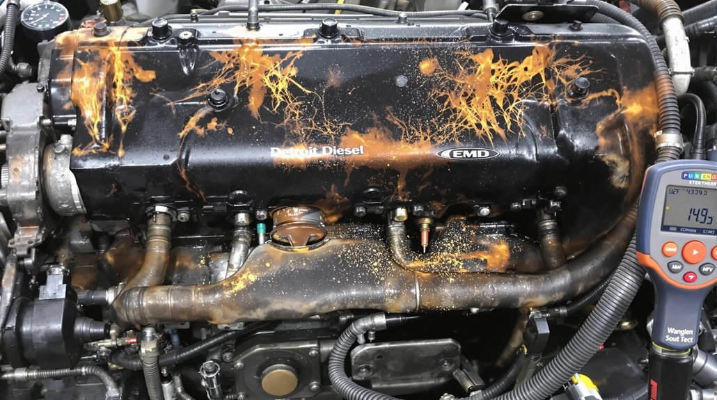
Recognizing deteriorating EMD power assemblies before catastrophic failure requires vigilant monitoring of key indicators. You’ll need to establish systematic inspection protocols focusing on three primary diagnostic categories: cooling system integrity, mechanical vibrations, and fluid characteristics.
| Warning Category | Key Indicators | Action Required |
|---|---|---|
| Cooling System | Pressurized coolant leaks, level fluctuations | Pressure test system, inspect cylinder linings |
| Vibration Patterns | Metallic knocking, lateral oscillations | Conduct vibration analysis at variable RPMs |
| Fluid Integrity | Lube oil contamination, blow-by gas | Sample oil for coolant presence, measure crankcase pressure |
| Thermal Performance | Low cooling pressure, heat exchanger efficiency | Evaluate thermal gradients across components |
| Auditory Signals | Grinding noises, harmonic resonances | Use acoustic monitoring during load shifts |
When you detect coolant leaks combined with visual staining on crankcase components, immediately investigate liner integrity. Implement vibration analysis during speed changes – increased lateral movement typically indicates bearing wear or piston carrier damage. Consider implementing a performance monitoring program that tracks power output and operating temperatures to identify failing power assemblies before they cause operational disruptions.
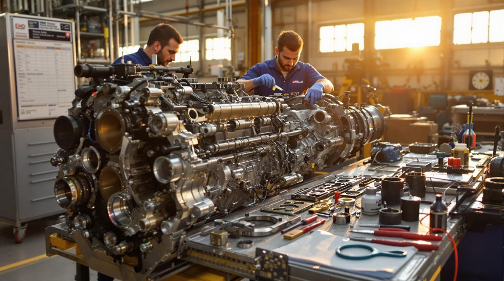
Essential Tools for EMD Engine Diagnostics

Building upon effective detection methods, proper EMD engine diagnostics require specialized equipment for accurate fault isolation and repair. You’ll need advanced diagnostic software like Jaltest or Roadwarrior Diesel Decoder that provides real-time parameter monitoring and actuator testing capabilities.
Essential tools include calibrated torque wrenches for precise component assembly and ultrasonic cleaners for parts restoration. Implement vibration analysis tools to detect rotating component imbalances before catastrophic failure occurs. Recent diagnostic trends emphasize emissions testing equipment integration for thorough performance evaluation. Technicians should incorporate data analysis techniques to utilize historical engine performance for more informed diagnostic decisions.
Precision diagnostics demand calibrated tools, from torque wrenches to vibration analyzers, preventing failures before they cascade into costly repairs.
Software advancements now enable VIN-specific data tracking and system configuration adjustments for peak performance based on operating conditions. Your diagnostic workflow should incorporate live data streaming to compare current readings against established baselines. Fault code interpreters translate cryptic alphanumeric sequences into actionable repair procedures.
For thorough power assembly diagnostics, combine these digital tools with physical inspection equipment like specialized mirrors for hard-to-reach visual assessments of critical components.
Step-by-Step Inspection Procedures

Thorough inspection of EMD power assemblies demands systematic procedures to identify failure points before catastrophic breakdown occurs. Begin by removing airbox and crankcase covers to access critical components, then deploy fiber optic borescopes to examine internal surfaces without full disassembly. Pressurize cooling systems to reveal hidden leaks at cylinder block seals and manifold sleeves. Using a specialized turning jack allows for efficient and safe inspection of moving engine components during the evaluation process.
Comprehensive failure diagnosis requires sequential verification:
- Test cylinder compression to assess ring sealing efficiency and detect breech leaks
- Verify cooling system integrity through pressure testing and contaminant analysis
- Evaluate gear train component alignment, checking backlash between camshaft, idler, and crank gears
Document all inspection findings meticulously, prioritizing repair actions based on severity. After completing repairs, conduct verification testing—particularly cooling system re-bleeding and lateral play assessment—to ascertain proper assembly. These inspection techniques establish a methodical approach that prevents catastrophic failures before they occur.
Oil Analysis and Lubrication Management

Effective oil analysis serves as the cornerstone of EMD power assembly reliability, revealing internal component conditions before catastrophic failures occur. Implement quarterly sampling protocols to track contamination trends and lubricant degradation rates specific to your operational environment.
Proactive oil sampling reveals hidden engine conditions, preventing failures before they manifest in your EMD power assemblies.
Deploy high-efficiency filtration systems to remove metal particles and contaminants that accelerate component wear. Your oil analysis program should monitor viscosity shifts, TBN/TAN values, and particulate counts to establish baseline parameters and detect deviations requiring intervention. Asking the repetitive why when interpreting oil analysis results helps uncover hidden causes of contamination rather than just addressing symptoms.
Integrate lubrication strategies that address EMD-specific requirements, including proper oil change intervals based on operating conditions rather than fixed schedules. Maintain strict documentation of all oil analysis results for pattern recognition across your fleet. When analysis indicates elevated metal content, promptly investigate potential component failures within the power assembly.
Correlate oil sample data with operational metrics to develop predictive maintenance protocols that extend power assembly service life while minimizing downtime.
Proper Bearing Replacement Techniques

Maintaining proper EMD bearing performance requires precise lubrication with OEM-specified SAE 40 oil applied at 15-20% capacity to prevent overheating and guarantee ideal clearance. You’ll need to follow the manufacturer’s torque sequence chart, applying 85-95 ft-lbs to main bearing caps and 45-55 ft-lbs to connecting rod bearings using a calibrated torque wrench with 2% accuracy. When installing new bearings, ensure that proper tooling is used to prevent damage to components. Verify bearing alignment using a dial indicator to measure crankshaft runout (maximum 0.002″ tolerance), then conduct clearance checks with Plastigage strips across each bearing surface to confirm the 0.003″-0.005″ specification.
Bearing Lubrication Requirements
When replacing bearings in EMD power assemblies, proper lubrication serves as the foundation for operational reliability and extended service life. Select appropriate lubricant based on operating conditions—grease types for low-speed applications, oil with correct viscosity for high-temperature environments exceeding 70°C.
Initial greasing requirements demand careful calculation:
- Fill 30-100% of bearing volume depending on application specifics
- Confirm lubrication holes direct grease directly to bearing surfaces without detours
- Verify material compatibility between grease base and bearing components
For EMD applications with high loads or temperatures, implement circulating oil systems to transfer heat away from critical components. Monitor oil levels at 50-80% submergence for vertical shafts. Track temperature fluctuations and adjust relubrication intervals accordingly—reduce intervals by half for every 15°C rise above 70°C. Synthetic oils are recommended when operating in extreme conditions as they offer superior performance at temperature extremes and specific environmental challenges.
Installation Torque Specifications
Beyond proper lubrication, precise torque application represents the cornerstone of successful EMD power assembly bearing replacement. You’ll need to maintain torque accuracy across all critical components to guarantee peak performance.
Apply 1,800 ft-lbs to cylinder head crab nuts on 567-series engines, exercising extreme caution to prevent bearing damage. Main bearing nuts require 500-800 ft-lbs with subsequent retightening after thermal cycling for assembly precision. Fork rod capscrews demand 190-200 ft-lbs, with verification through serration inspection.
Don’t overlook split basket bolts, which require 75 ft-lbs for bottom bolts in multi-piece assemblies. When working with cramped F-units, proper torque wrench positioning becomes especially challenging. For flywheel couplings, maintain 295 ft-lbs on all 3/4″ x 16 bolts. Your adherence to these specifications directly correlates with component life expectancy and system reliability.
Alignment Verification Methods
Proper alignment verification stands as the foundation of successful EMD power assembly bearing replacement. When installing components, you’ll need specialized alignment tools to guarantee critical fits meet specifications and prevent premature failures.
Key verification techniques include:
- Crankcase serration measurement – Utilize gauge #8177167 to verify distortion remains within ±0.003″ tolerance, guaranteeing proper bearing cap seating and frame alignment.
- P-pipe alignment verification – Insert the specialized checker tool into the cooling nozzle during carrier descent to confirm proper oil passage alignment; replace misaligned pipes immediately.
- Shaft-to-bearing fit confirmation – Compare outside shaft diameter to bearing inner diameter using calibrated micrometers to validate proper interference fit before final assembly.
Monitor vibration patterns post-installation to detect any residual misalignment issues that might compromise long-term power assembly performance. Implementing vibration analysis techniques during initial operation provides early detection of potential bearing failure modes.
Master/Slave Rod Configuration Considerations

When configuring master/slave rod assemblies, you’ll need to guarantee equal spacing between slave rods to maintain proper load distribution across the banjo connections. Position slave rod pins with precise angular offsets around the master rod to prevent stress concentration during reciprocating cycles under high loads. Verify dimensional compatibility between master rod bores and slave rod housings, maintaining zero lash while guaranteeing adequate travel characteristics for full actuation. The slave rod pins are typically arranged along a radial line from the master crank pin center, which significantly influences the overall engine geometry and timing.
Rod Alignment Essentials
Master/slave rod configurations present unique alignment challenges that directly impact EMD power assembly reliability. When servicing these assemblies, you’ll need to verify proper rod geometry to maintain cylinder balance across all opposed pairs. Critical articulation points must maintain precise dimensions to prevent elliptical trajectory deviations that introduce harmful vibrations.
During reassembly, confirm:
- Big-end bearings exhibit uniform clearance with replaceable caps properly torqued to specification
- Master rod bearing surfaces show no signs of scoring that could compromise slave rod articulation
- Offset measurements between master/slave stroke lengths remain within 3% tolerance across banks
Check that master rods align precisely with the crankshaft at TDC/BDC positions while slave rods maintain proper angular displacement. This alignment prevents oscillatory stresses that lead to premature failure in high-load conditions.
Load Distribution Mechanics
Understanding load distribution mechanics forms the foundation of reliable EMD power assemblies where fork-blade rod arrangements create unique force transmission challenges. Your fork (master) rod bears primary loads through its basket structure, while the blade (slave) rod functions within this guided mechanism.
During load testing, monitor for improper fitment causing uneven journal wear. The fork rod’s ability to maintain alignment directly affects the blade rod’s operational integrity. Always verify torque sequencing on basket bolts per manufacturer specifications to prevent warped joints.
Rod materials considerably impact durability—inspect fork rod baskets for preload loss and blade journals for alignment shift during maintenance. Document load cycles to identify fatigue-prone configurations. Remember that coolant ingression often precedes catastrophic failures, so prioritize cooling system integrity checks when troubleshooting power assembly issues.
Replacement Compatibility Guidelines
Selecting compatible replacement components for EMD power assemblies requires precise attention to master/slave rod configurations. When sourcing replacement parts, distinguish between straight-pin (master) and rocking-pin (slave) assemblies to maintain proper load distribution across your engine. Compatibility verification must include checking compression ratios before installation.
- Verify pin configuration – Confirm whether you need straight pins (16:01 compression) or rocking pins (14.5:1) based on your EMD model specifications.
- Cross-reference part numbers – Match OEM designations between 645E, 645E3, or 710 series components for proper fitment.
- Check supplier documentation – Ascertain vendor materials explicitly state master/slave compatibility with your specific rod types (fork, blade, or partial pack).
Never intermix incompatible configurations without recalibrating governor settings and fuel injection timing.
Preventive Maintenance Scheduling for Longer Assembly Life
Implementing a structured preventive maintenance schedule dramatically extends EMD power assembly life while reducing catastrophic failures and unplanned downtime. Your preventive strategies should align with operational demands and manufacturer specifications, incorporating daily fluid checks, weekly electrical inspections, and monthly traction motor diagnostics.
| Maintenance Interval | Critical Tasks | Component Focus |
|---|---|---|
| Daily/Weekly | Fluid level monitoring, filter inspections | Lubrication systems, air intakes |
| Monthly/Quarterly | Traction motor diagnostics, EMD power metrics | Drive components, coolant systems |
| Biannual/Annual | Component replacement, turbocharger maintenance | Filters, seals, bearings |
Maintenance frequency optimization requires balancing operational demands with component lifecycle assessments. Conduct coolant condition analysis weekly, perform electrical component cleaning monthly, and execute power assembly diagnostics quarterly. You’ll achieve maximum reliability when integrating EMD diagnostic software utilization with physical inspections, particularly when validating turbocharger efficiency and braking system functionality.
Frequently Asked Questions
Can Power Assemblies From Different EMD Engine Series Be Interchanged?
Limited power assembly compatibility exists between EMD engine series. You’ll find 645-series assemblies can sometimes replace 567D turbocharged units, but you must verify critical dimensions like bore size and head bolt patterns. Consider camshaft counterweight adjustments when interchanging components. Engine series differences in cylinder liner designs, piston ring specifications, and bearing configurations will restrict direct substitutions. Always check OEM specifications before attempting cross-series installations to prevent operational failures.
How Does Ambient Temperature Affect Power Assembly Failure Rates?
Ambient conditions greatly influence power assembly failure rates. In high-temperature environments, you’ll experience accelerated electrolytic capacitor deterioration, reducing lifespan by 50% per 10°C above rating. Temperature effects include PTC-induced efficiency losses in MOSFETs and dielectric breakdown under thermal stress. Conversely, cold ambient conditions decrease capacitance, compromising ripple voltage regulation and increasing inrush current limiter resistance, potentially preventing startup below minimum operational temperatures.
Is Ultrasonic Testing Effective for Detecting Internal Power Assembly Cracks?
Ultrasonic testing detects cracks as small as 30 µm deep—superior to alternative NDT methods. You’ll achieve ideal ultrasonic sensitivity through waveform analysis rather than relying solely on time-of-flight measurements. Deploy longitudinal waves for transverse crack detection and transverse waves for longitudinal defects. Phased array technology, particularly Fermat spiral probes, greatly enhances crack detection precision while requiring appropriate coupling media for maximum effectiveness during your power assembly inspections.
What Emission Modifications Impact Power Assembly Reliability?
Emission modifications greatly impact your power assembly reliability when they alter combustion characteristics. When retrofitting for emission standards, you’ll face increased thermal cycling and cylinder pressures. Monitor fuel injection timing closely as retarded timing reduces NOx but increases thermal stress. Enhanced SCR systems require power assembly design adjustments to handle altered exhaust backpressure. Always recalibrate injectors after modifications to prevent uneven combustion that accelerates component fatigue.
How Do Aftermarket Components Compare to OEM for Power Assembly Longevity?
When comparing aftermarket components to OEM parts, you’ll find significant longevity differences. OEM durability stems from precision engineering, rigorous testing protocols, and material quality standards exceeding aftermarket alternatives. Aftermarket reliability varies substantially between suppliers, with most components utilizing inferior materials that accelerate wear patterns. While initially cost-effective, aftermarket parts typically require 2-3x more frequent replacement cycles and lack warranty protection that OEM components provide, ultimately compromising your power assembly’s operational lifespan.