
You’ll guarantee reliable EMD locomotive performance by inspecting bearings thoroughly during removal, measuring clearances with Plastigage to maintain proper specifications, and aligning camshafts using factory tool 8212763. Position oil holes at 4:00 o’clock for ideal lubrication, apply EP grease to contact surfaces, and clean all galleries entirely. Replace seals with precise 3/32″ protrusion, torque drive plugs to 100-120 ft-lbs per EMD specifications, verify tolerances don’t exceed 0.015″, and document everything meticulously. These procedures form the foundation for extensive bearing maintenance protocols.
Key Takeaways
- Apply 650 ft-lbs torque on EMD 567C main bearings and use Plastigage for accurate oil clearance measurements.
- Position oil holes downward at 4:00 clock position to ensure optimal lubrication flow during operation.
- Use factory-specified alignment tools like tool 8212763 with dial indicators maintaining ±0.001″ accuracy for precise positioning.
- Apply premium-grade EP grease to bearing surfaces before installation to prevent metal-to-metal contact during startup.
- Document six measurements per bore and maintain ≤0.004″ alignment deviation for proper oil distribution compliance.
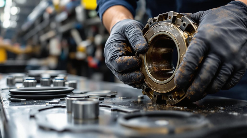
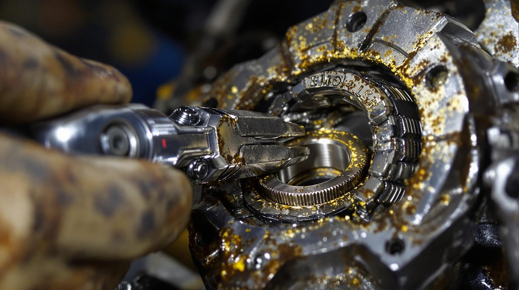
Inspect Bearings Thoroughly During Removal to Assess Replacement Requirements
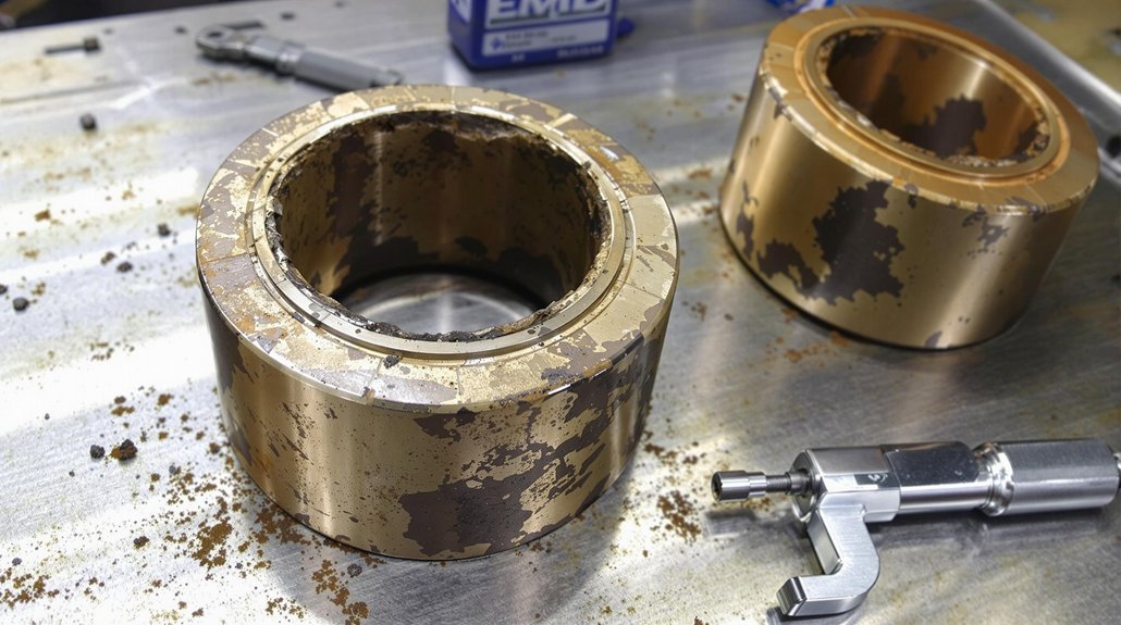
Before you begin camshaft bearing removal, establish a systematic inspection protocol that’ll preserve critical diagnostic information and prevent costly oversights. Use OEM-approved tools like ball micrometers and dial indicators for precise bearing inspection measurements. Compare all findings against EMD-established tolerances to determine replacement criteria.
During visual examination, identify heat discoloration, scoring, pitting, or fretting on bearing surfaces. Check camshaft journal concentricity relative to bearing bores using serration gauges to detect misalignment. Inspect oil feed holes with magnifying glass or borescope, ensuring passages remain clear of carbon buildup.
Mark bearing orientation using center punch before removal to prevent side reversal during reassembly. Match wear patterns with original cap positions using existing fret marks. Reject bearings immediately if they exhibit metal transfer or fretting depth exceeding manufacturer limits. Document all defects systematically in maintenance logs for trend analysis and compliance with EMD protocols. Verify that EP additive lubricant has been properly applied to all bearing surfaces before conducting the final inspection checks.
Measure Bearing Clearance Precisely to Prevent Camshaft Flex Issues
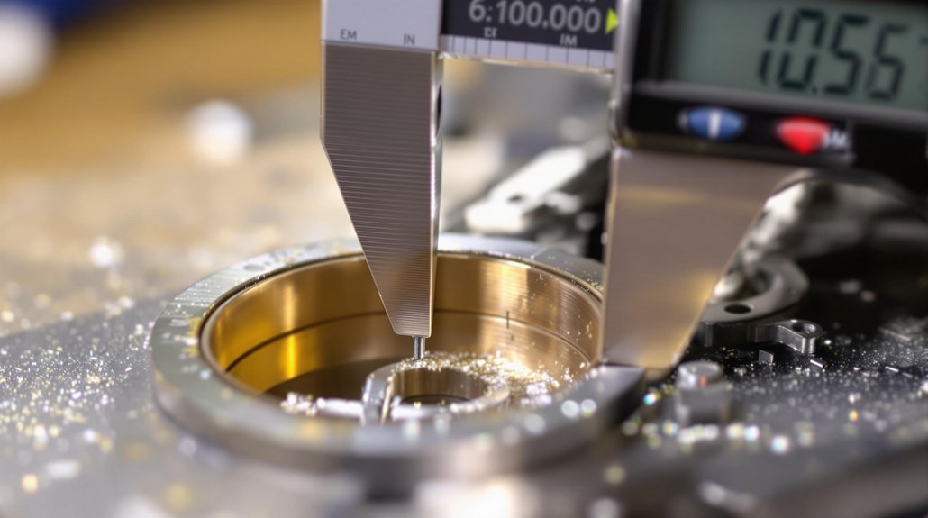
After completing your bearing inspection and documentation, measuring bearing clearance becomes your next critical step in preventing costly camshaft failures. Use plastic gauges (Plastigage) for accurate oil clearance checks, ensuring zero camshaft rotation during measurement. Apply 650 ft-lbs torque on EMD 567C main bearings before taking measurements to assess out-of-round tolerances.
Your bearing measurement techniques must include dial indicators and micrometers to verify journal diameters. Document six measurements per bore—three per end—to calculate accurate averages for compliance with camshaft clearance standards.
| Shell Combination | Expected Clearance | Application |
|---|---|---|
| Half-standard + Standard | 2.5 thou | Ideal fit |
| Half-standard + Standard X | >3 thou | Looser tolerance |
| Full Standard X | >3 thou | Maximum clearance |
| Standard + Standard | Variable | Standard operation |
| Shimmed Configuration | Adjustable | Custom applications |
Calibrate all measurement tools before use and avoid contamination during Plastigage tests to prevent skewed readings that compromise bearing performance. Remember that wider gauge measurements indicate reduced oil clearance, requiring immediate attention to prevent bearing damage.
Align Camshaft With Engine Guides Using Factory-Specified Tools
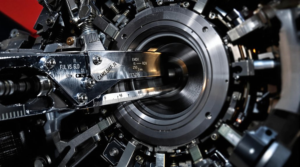
You must use factory-specified tools like tool 8212763 when installing aligning components into engine guides to guarantee precise camshaft positioning. Proper tool assembly requires compressing inserts on puller plates and aligning them with spindle shoulders before driving into position. Following these precision alignment procedures prevents costly misalignment issues that can cause premature bearing failure and excessive vibration. Use dial indicators to measure any radial or angular misalignment during the camshaft installation process to ensure optimal bearing performance.
Factory Tool Requirements
When aligning camshaft components in EMD locomotives, you’ll need factory-specified tools that guarantee precise bearing installation without damaging critical engine components. Tool compatibility becomes critical when selecting equipment like Cloyes Timing Camshaft Gear Installation Tools with spline-drive configurations for 13/16″ hex sizes. JEGS Cam Bearing Tool Set (Part #555-80597) provides specialized adaptors essential for proper installation techniques in EMD applications.
Essential factory tool requirements include:
- Extended alignment bars (24″ & 55″ lengths) for leveraging camshaft guides without bearing damage
- Monaco Tool Cam Bearing Adaptor Kits with engine-specific configurations for locomotive applications
- Precision micrometers and dial indicators maintaining ±0.001″ accuracy for clearance verification
- Woodruff keys ensuring exact shaft-to-drive-gear alignment per EMD timing specifications
Professional installation demands tools manufactured from high-quality materials to ensure consistent performance throughout the bearing installation process. These specifications align with industry standards for locomotive maintenance operations requiring maximum durability and precision tolerances.
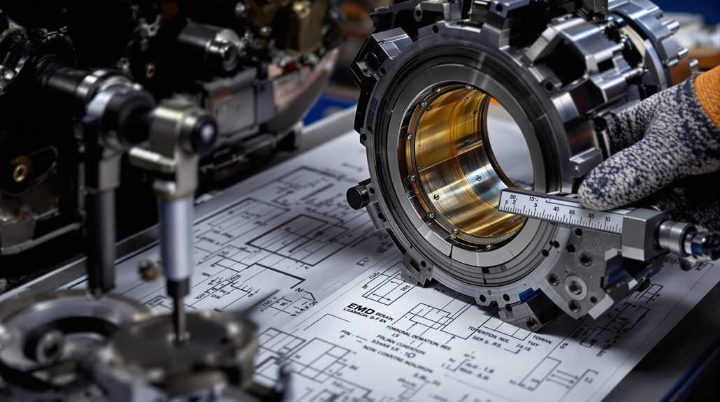
Precision Alignment Procedures
Mount dial indicators on surface gauges to measure vertical bore alignment relative to case line data. Zero your indicators at the No.1 main bearing bore’s accessory end as your reference point. Record readings at main foundation mounting points, ensuring discrepancies remain under 0.25 mm.
Cross-check camshaft positioning against manufacturer guides for cylindrical surfaces and keyways. Your installation tools must integrate with EMD-specific equipment like 8212763/8212764 for precise bore alignment. Calculate case line data mathematically, combining vertical measurements with reference specifications to verify proper camshaft materials positioning before final assembly.
Use precision tools like dial bore gauges and micrometers to verify bearing clearances according to EMD specifications throughout the alignment process.
Position Oil Holes Downward for Optimal Lubrication Flow Distribution
Although proper camshaft bearing installation requires multiple crucial steps, positioning oil holes downward stands as the most important factor for maintaining consistent lubrication flow in EMD locomotives. When you’re installing camshaft bearings, you’ll need to position oil holes at the 4:00 clock position to counter journal downward pressure effectively. This oil hole positioning creates ideal lubrication optimization by working with gravity rather than against it.
Never position holes at 6:00, as this risks complete oil shut-off under load conditions. You must maintain ≤0.004″ deviation during alignment to guarantee proper oil distribution throughout the bearing surface.
Key positioning requirements include:
- Orient holes based on clockwise rotation direction for proper flow dynamics
- Avoid loaded areas where high pressure excludes oil from critical surfaces
- Align with engine feed passages in non-grooved lubrication systems
- Account for centrifugal forces that affect oil distribution at operating speeds
Proper hole positioning prevents premature bearing failure and maintains consistent lubrication under all operating conditions. The 4:00 o’clock position allows oil to be pulled around by cam rotation, ensuring continuous lubrication flow during operation.
Apply EP Grease to Bearing Contact Surfaces Before Installation
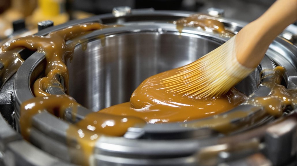
You’ll need to apply premium-grade extreme-pressure (EP) grease to all bearing contact surfaces before installing camshaft bearings in your EMD locomotive. This specialized lubricant provides critical protection during initial startup when oil pressure hasn’t yet established full hydrodynamic lubrication. Proper application technique guarantees uniform coverage across bearing journals and prevents metal-to-metal contact that could damage expensive components. Remember that main bearings should be replaced one at a time to maintain proper oil clearance throughout the engine assembly.
EP Grease Benefits
Three critical performance characteristics make EP (Extreme Pressure) grease essential for EMD locomotive camshaft bearing installations. The sulfur-phosphorus additives in EP grease formulation prevent metal-to-metal contact during startup cycles when oil film hasn’t fully developed. You’ll achieve superior protection against wear under high mechanical stress conditions typical in locomotive duty cycles.
EP grease delivers exceptional heat resistance up to 200°C+, maintaining stable viscosity through repeated thermal cycling. The lithium-based thickener guarantees compatibility with bearing metals while extending lubrication intervals beyond 30,000-mile equivalents. Anti-corrosion additives protect ferrous components in humid environments, while tackiness agents maintain adhesion during high-speed rotation. Proper application prevents engine seizing during the critical initial startup phase when oil pressure systems are still building.
- Base oil stability prevents degradation under extreme temperature fluctuations
- NLGI Class 2 consistency balances pumpability with placement accuracy
- Antioxidants neutralize acidic byproducts from thermal oxidation
- Microscopic fillers provide additional anti-wear protection during boundary lubrication
Proper Application Technique
Before installing camshaft bearings in EMD locomotives, you must apply EP grease with meticulous precision to guarantee peak performance and prevent premature failure. Clean each bearing surface thoroughly with solvent to eliminate contaminants that compromise adhesion. Apply grease exclusively to bearing inner surfaces using calibrated applicator gauges, working in a radial pattern from center to edge. This prevents air pockets while ensuring even distribution across load paths.
Never coat outer diameters or engine block surfaces, as this creates improper fits. Remove excess grease with lint-free cloth to maintain controlled thickness. Work sequentially across surfaces at consistent room temperature to preserve grease viscosity. Verify that oil feed holes are properly aligned and unobstructed by grease to ensure adequate lubrication flow during operation. Post-grease application, inspect all surfaces to confirm proper coating without excessive buildup that could migrate during operation.
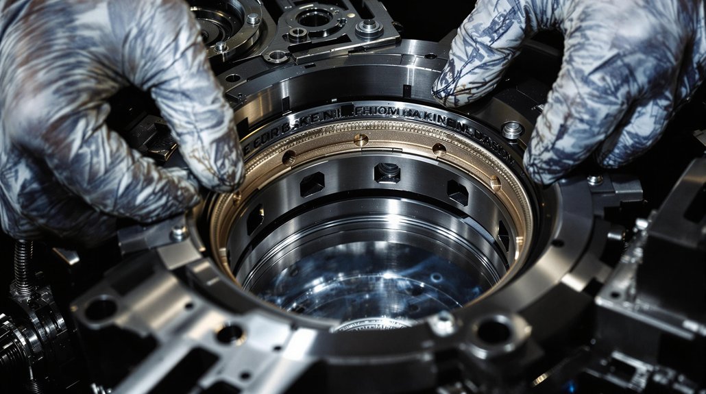
Use Specialized Insert Compressors for Dimensionally Accurate Fitting
Two critical factors determine successful camshaft bearing installation in EMD locomotives: precise diameter reduction and controlled insertion force. You’ll need specialized insert compressor types like tool 8212763 to achieve the dimensional accuracy required for fitting bearings through restricted bore openings. These installation techniques guarantee proper alignment while preventing radial stress damage to camshaft bore surfaces.
Your compressor tool selection directly impacts bearing longevity and engine performance. Component-specific assembly sequences maintain critical alignment tolerances during insertion operations. Prior to bearing installation, main caps should be torqued to manufacturer specifications to ensure proper block stability.
- Use striker-driven force application for controlled thrust, minimizing stress on bore surfaces
- Verify marked positional alignment between tool strike surfaces and bearing boundaries
- Apply multistage spindle preparation with compressing tools (8212764) secured by threaded fasteners
- Confirm insert orientation aligns with cylinder bore geometry for proper shoulder thread engagement
Always perform dimensional clearance verification using precision micrometers after insertion to validate manufacturer specifications before proceeding with reassembly procedures.
Clean All Oil Galleries and Passages to Eliminate Debris Blockages
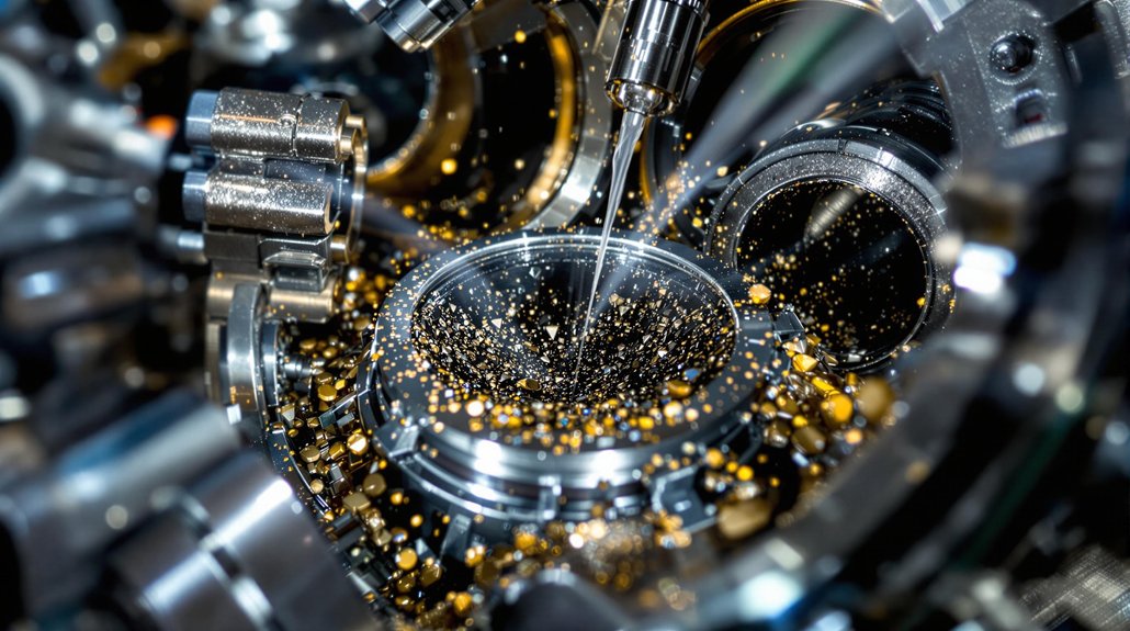
You’ll need systematic debris detection methods to identify contaminants that could compromise camshaft bearing lubrication in your EMD locomotive. Start by conducting thorough oil hole inspections and bore gauging to locate blockages, followed by water contamination checks and dirt impregnation detection on all bearing surfaces. Implement proper gallery flushing techniques using high-pressure washing and pressure testing to guarantee complete debris removal before bearing installation.
Debris Detection Methods
Why do experienced technicians prioritize thorough debris detection before installing camshaft bearings? Contaminated oil galleries create catastrophic bearing failures, making extensive debris detection crucial for successful EMD locomotive maintenance. You’ll need to identify debris sources ranging from metal particles to coolant contamination that compromise bearing longevity. Advanced detection techniques guarantee your installation meets strict cleanliness standards.
Critical debris detection methods include:
- Ferrography analysis – Use bichromatic microscopes to differentiate metallic particles from nonmetallic contaminants in oil samples
- Particle size distribution testing – Monitor debris above 10 microns that indicates worn components or inadequate filtration
- SEM/EDS analysis – Determine particle composition and origin for precise contamination source identification
- Silicon level tracking – Detect airborne contaminants penetrating through compromised seals or vents
Exception testing protocols trigger immediate corrective action when contamination exceeds safety thresholds.
Gallery Flushing Techniques
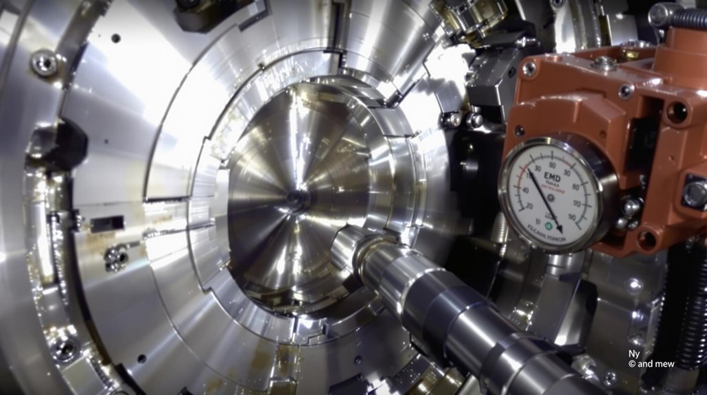
After identifying contamination through thorough debris detection, you must execute systematic gallery flushing to eliminate every trace of debris from EMD camshaft bearing oil passages. Deliver high-speed fluid flows through galleries to maximize flushing efficiency while attaching dedicated tools to penetrate narrow passages and blind spots.
| Flushing Parameter | Specification | Safety Requirement |
|---|---|---|
| Flow Direction | Alternating sequences | Monitor pressure gauges |
| Engine Position | Vertical/horizontal | Secure on reinforced fixtures |
| Gallery Isolation | Temporary blocking | Prevent debris migration |
| Temperature Control | Consistent levels | Avoid thermal expansion |
Sequence operations through interconnected galleries ensuring full coverage. Position engine blocks based on design accessibility and alternate flushing directions for complex geometries. Gallery isolation prevents debris migration during operations. Calibrate pressure gauges within manufacturer-recommended ranges and integrate overflow safety valves.
Replace Seals and Drain Plugs to Prevent Oil Leakage
Three critical seal replacement procedures form the foundation of preventing oil leakage during camshaft bearing installation in EMD locomotives. Your seal material selection directly impacts long-term performance, particularly when using phosphate-treated cast iron inserts for lower liner bores under high rotational stresses. Master these installation techniques to guarantee proper sealing between oil pan, crankcase, and end housing components.
Cut seal cord ends precisely to achieve 3/32″ ± 1/64″ protrusion from end plate faces. Apply sealing compound (P/N 8222724) to insert split lines, preventing air infiltration between lower liner bore inserts and liners. Verify groove cleanliness in lower cylinder liner pilots before inserting new seals.
Essential drain plug maintenance procedures include:
- Inspect drain plugs for cracks, corrosion, or thread damage before reinstallation
- Clean sealing surfaces with lint-free rags after oil drainage
- Replace scavenging pump strainer housing seals and verify drainage valve closure
- Pressure test all drain valve seals and gasket bounding surfaces post-assembly
Torque Drive Plugs to Manufacturer Specifications for Secure Installation
Torquing drive plugs to precise manufacturer specifications prevents catastrophic bearing failures and maintains structural integrity throughout your EMD locomotive’s operational cycle. Use torque wrench 8157121 with extension 8210136 for accurate application, ensuring your 3/8″ drive torque wrench produces an audible click confirmation. Drive plug connections typically require 100–120 ft-lbs torque, following EMD Spec 8091 compliance standards.
Perform torque calibration before each installation sequence to eliminate over-or under-torquing risks that compromise bearing assemblies. Apply torque in graduated increments rather than single applications, checking for proper thread engagement throughout the process. Non-calibrated tools create dangerous installation variables that’ll lead to premature component failure.
Complete installation verification by rechecking torque values after initial setup to confirm stability. Record all torque specifications for future maintenance reference, ensuring FRA-mandated safety tolerances are met. Dynamic testing post-installation verifies secure drive plug positioning and validates proper camshaft bearing operational parameters.
Verify Installation Tolerances and Document for Future Reference
Once you’ve completed the drive plug torque sequence, verify installation tolerances using precision measurement tools to confirm your camshaft bearing assembly meets EMD’s critical specifications. Proper tolerance verification guarantees peak bearing performance and prevents premature failure in locomotive service conditions.
Document all measurements systematically to establish an all-encompassing maintenance baseline. Record bearing clearances, alignment positions, and any dimensional variations that fall within acceptable parameters. Your documentation practices should include serial number tracking, installation dates, and technician identification for complete traceability.
- Bearing clearance measurement: Use precision gauges to verify diametral clearances don’t exceed 0.015″ specifications
- Alignment verification: Confirm camshaft position relative to numbered cylinder banks in V8 configuration
- Seal integrity documentation: Record 3/32″ ± 1/64″ seal height compliance at critical junction points
- Maintenance record integration: Update service history with ISO-standard reporting formats for audit compliance
Store all alignment datasheets with your locomotive’s service documentation for future reference and trend analysis.
Frequently Asked Questions
What Are the Common Signs of Bearing Wear That Indicate Immediate Replacement?
You’ll hear distinct bearing noise like knocking or grinding sounds that signal immediate replacement needs. Watch for oil pressure drops and metal shavings indicating friction damage. Check for engine misfires caused by timing disruptions. Examine bearing surfaces for scoring, pitting, or shiny areas from metal contact. Oil contamination with dark discoloration shows overheating damage. Don’t delay replacement when these critical warning signs appear.
How Often Should Camshaft Bearings Be Replaced in EMD Locomotives?
Coincidentally, bearing wear signs you’ve identified align perfectly with EMD’s established replacement intervals. You’ll replace camshaft bearings every 3 years, 1,367,905 km, or 23,000 MWh during major overhauls on GT46MAC models. Follow maintenance guidelines strictly—don’t rely solely on condition-based decisions. You must adhere to these fixed intervals regardless of apparent bearing condition, as EMD’s procedural requirements guarantee reliability and prevent catastrophic failures through proactive replacement scheduling.
Can Aftermarket Bearings Be Used Instead of OEM Parts for EMD Engines?
You can use aftermarket bearings if they meet strict aftermarket compatibility requirements. Ascertain exact OEM dimensional matching – bore size must be 2.333″ ±0.0005″ for HC-1/HC-2 types. Performance comparison shows aftermarket options like Hamilton Cams’ bearings cost $18.99 versus OEM pricing, but material quality must equal or exceed EMD standards. Verify thermal expansion coefficients, tensile strength, and thickness specifications match exactly to prevent catastrophic engine failure and warranty voidance.
What Causes Premature Camshaft Bearing Failure in Diesel Locomotive Applications?
Like a marathon runner hitting the wall at mile twenty, your camshaft bearings face inevitable breakdown under relentless mechanical stress. You’ll encounter premature failure primarily through camshaft lubrication issues—blocked oil galleries starve bearings of essential film protection. Poor installation creates misalignment, while contaminated oil introduces abrasive particles. Bearing material fatigue accelerates under thermal expansion and excessive loads, causing surface deterioration that compromises your locomotive’s valve timing precision.
Are There Different Bearing Specifications for Various EMD Locomotive Models?
Yes, you’ll encounter distinct bearing specifications across EMD models. Different bearing types include segment bearings in 567C engines versus bracket-integrated bearings in 645 series. You must verify model compatibility since 567C uses segment bearings with flanged caps, while 645 camshafts incorporate bearing brackets within drive gear assemblies. Early models like SW1001 specify Timken tapered roller bearings, whereas later GP40-2 designs require Hyatt roller bearings with crowned rollers for extended service life.
You may also like to read – EMD Owners Group Procedure EMD9314.