
A weak cooling fan can trigger overheating, power loss, and unplanned locomotive downtime. Many operators struggle to link fan speed, airflow, and radiator resistance. The main issue is simple. The fan must move enough air through the radiator core under real operating conditions, not just at rated speed.
- Low airflow reduces radiator heat rejection.
- Excess blade pitch can increase stall risk.
- Poor shroud sealing cuts fan efficiency.
- Large tip clearance increases leakage losses.
- Inlet distortion creates uneven blade loading.
- Wrong RPM shifts the fan away from duty point.
- High ambient temperature reduces cooling margin.
- Air density changes mass flow performance.
- Radiator resistance sets the actual operating point.
| Pain Point | Likely Cause | Practical Check |
|---|---|---|
| Engine overheating | Low airflow through radiator | Verify fan RPM and airflow path |
| Poor cooling at idle | Insufficient fan speed | Check drive performance |
| High fan power draw | Off-design blade loading | Review blade pitch and resistance |
| Uneven performance | Inlet distortion or blockage | Inspect ducts and guards |
| Lower efficiency | Tip leakage and separation | Check shroud and blade clearance |
A 48-inch locomotive cooling fan performs by converting shaft power into airflow and static pressure rise. Its axial blades act like rotating airfoils. They generate lift-based force on the air. That force drives air through the locomotive radiator system.
Blade pitch strongly affects airflow and pressure capability. Higher pitch can increase pressure. It can also raise drag and stall risk. Blade solidity also matters. More blade area usually improves pressure rise. It may also increase power demand.
Tip speed is another key factor. It depends on fan diameter and RPM. Higher tip speed usually increases airflow and pressure. It also raises noise, stress, and loss risk. Incidence angle must stay within a stable range. Poor incidence can cause flow separation.
The operating point does not depend on the fan alone. It comes from the fan curve crossing the radiator-system resistance curve. If system resistance rises, airflow drops. If fan speed rises, the duty point shifts higher.
Fan performance follows the basic fan affinity trends. Airflow changes roughly with RPM. Pressure changes more strongly with RPM. Power demand rises even faster. These trends help predict locomotive cooling performance during speed changes.
Real losses reduce ideal performance. Tip clearance allows leakage around the blade ends. Shroud leakage also lowers useful flow. Flow separation reduces blade efficiency. Inlet distortion creates non-uniform loading across the fan disc.
Air density also affects cooling. Lower density reduces mass flow at the same volume flow. That lowers radiator heat rejection. This is important in hot weather and high-altitude locomotive service.
At Mikura International, we support locomotive operators with genuine parts supply for ALCO, EMD, GE, and WABCO applications. Understanding these aerodynamic principles helps select the right fan-related components and maintain reliable locomotive cooling performance.
Key Takeaways
- The 48-inch axial fan converts shaft power into radiator airflow and pressure rise to overcome core, shroud, and duct resistance.
- Blade-element behavior varies by radius; higher tip speed changes local angle of attack, Reynolds number, loading, and stall margin.
- Airfoil-shaped blades generate lift that resolves into axial thrust, accelerating air and increasing static and total pressure.
- Fan performance is set by the operating point where blade pitch, solidity, and speed meet system resistance and pressure-flow demand.
- Efficiency and stability depend on limiting tip-clearance losses, vortices, and flow separation, which reduce pressure rise and airflow.
Introduction to Locomotive Cooling Fans
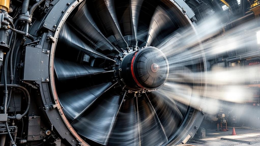
In locomotive thermal management, you rely on the cooling fan to move high air mass flow through the radiator core and reject engine heat at the required rate. Within this setting, the EMD 9518890 functions as a critical 48-inch axial unit whose Locomotive Fan Aerodynamics determine pressure rise, flow uniformity, and operating efficiency. As you analyze heat exchange, you’ll see that the fan converts shaft power into airflow and pressure differential, forcing ambient air across heat-transfer surfaces to maintain acceptable coolant and component temperatures.
Importance of fans in thermal management
Because a diesel locomotive rejects several megawatts of waste heat under load, its cooling fan becomes a primary thermal-management device rather than a simple accessory. You rely on it to sustain radiator airflow, control coolant temperature, and maintain engine, traction, and lube-oil limits across ambient extremes. If airflow drops, Thermal Heat Rejection falls nonlinearly, and component temperatures can rise within minutes.
As a result, you treat fan performance as a system-level variable, not an isolated rotating part. In Cooling System Modeling, you match volumetric flow, pressure rise, radiator resistance, and engine heat load to predict equilibrium temperature. A 48-inch axial fan can move tens of thousands of cubic feet per minute, directly setting convective coefficients and heat-exchanger effectiveness. In practice, fan capacity determines whether you preserve full power output or derate the locomotive under sustained thermal stress.
Overview of the EMD 9518890 as a critical component
That system-level role becomes concrete when you look at the EMD 9518890, a 48-inch axial cooling fan engineered to convert shaft power into high radiator airflow with enough pressure rise to overcome core and duct resistance. You can treat it as the aerodynamic heart of the cooling package, where blade solidity, pitch, and tip speed set the operating point against system resistance.
In Locomotive Fan Aerodynamics, you evaluate the 9518890 through Axial Fan Principles, Fluid Dynamics, and Fan Performance Curves. Its airfoil blades must delay Flow Separation, sustain pressure coefficient, and limit tip losses across a broad RPM band. You also track hub-to-tip loading distribution, because uneven loading cuts efficiency and raises vibration. Effective Noise Reduction depends on controlling turbulence, blade-pass interaction, and clearance-driven vortices under transient locomotive duty cycles.
Brief on how fans facilitate heat exchange
When the diesel engine rejects a large thermal load to coolant and charge-air circuits, the cooling fan enables heat exchange by forcing ambient air through radiator and intercooler cores at a volumetric flow rate high enough to sustain the required convective heat-transfer coefficient. You increase cooling airflow, reduce airside resistance effects, and raise convective cooling effectiveness.
| Variable | Effect |
|---|---|
| Airflow | Increases Heat transfer |
| Pressure rise | Overcomes core losses |
| Core velocity | Raises film coefficient |
| Airside resistance | Limits system flow |
| Fan speed | Sets thermal margin |
You can model removed heat as Q = hAΔT. Higher face velocity typically increases h, so more cooling airflow extracts more waste heat. However, pressure losses scale roughly with velocity squared, so the fan must supply sufficient static pressure for stable radiator performance.
Principles of Axial Fan Operation
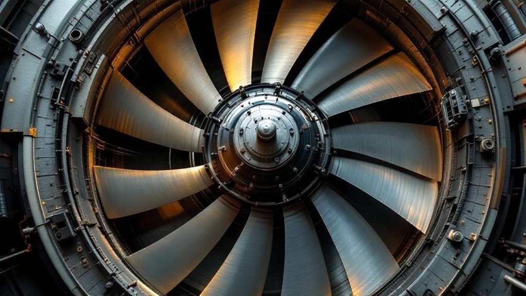
To understand Locomotive Fan Aerodynamics, you can treat each axial blade as a series of radial elements, each seeing a different relative velocity and angle of attack as rotational speed increases with radius. You’ll find that these elements generate lift and an axial thrust component by turning airflow, with Fluid Dynamics governed by local blade speed, pressure differential, and incidence angle. As you evaluate Axial Fan Principles, you can see that blade angle and airfoil shape set the balance between flow rate, pressure rise, and efficiency across Fan Performance Curves.
Blade element theory and airflow interaction
Because a 48-inch locomotive cooling fan doesn’t act as a single uniform surface, blade element theory treats each blade as a series of narrow radial sections, each seeing a different local velocity and angle of attack. You evaluate each strip by radius, relative speed, and incidence, then sum contributions to predict flow and pressure. Blade chord mapping sets local solidity, while Turbulence control preserves attached flow.
| Radius | Relative velocity | Design focus |
|---|---|---|
| Hub | low | stall margin |
| Inner midspan | moderate | chord loading |
| Midspan | higher | efficient incidence |
| Outer midspan | high | loss control |
| Tip | highest | leakage mitigation |
Since tangential speed scales with radius, the tip may run about 2.5× faster than inner sections. That gradient changes Reynolds number, boundary-layer behavior, and local flow turning under radiator resistance.
Generation of lift and thrust by rotating blades
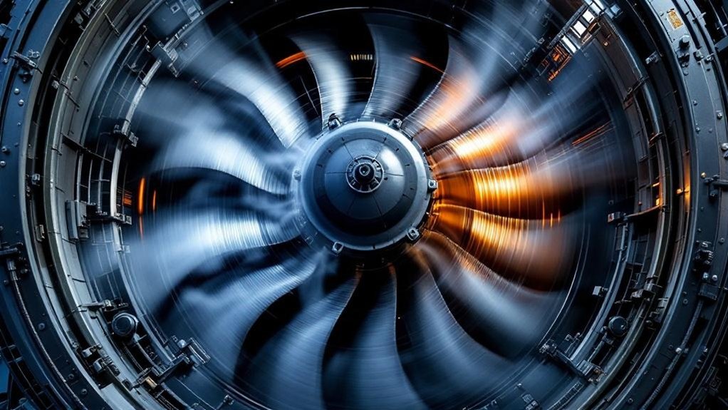
Although an axial locomotive fan appears to simply “push” air, each rotating blade actually works as a moving airfoil that generates lift perpendicular to the local relative airflow and resolves part of that force into axial thrust. As the fan rotates, you combine blade tangential velocity with incoming axial velocity to define relative flow and dynamic pressure, 0.5 rho V^2.
The blade’s lift vector has axial and circumferential components; the axial component accelerates air rearward, while the torque reaction sets power demand. By Newton’s third law, that momentum increase produces thrust and a measurable pressure rise across the fan. Near the tip, higher speed strengthens lift but also intensifies Blade Tip Vortices and induced losses. Consequently preserve Stall Margin so attached flow remains stable under changing locomotive cooling loads and operating conditions.
Role of blade angle and shape in aerodynamic force generation
Blade angle and blade shape determine how efficiently that lift-producing mechanism converts shaft power into airflow and pressure rise in a 48-inch axial locomotive fan. You control local angle of attack through twist, setting higher pitch near the hub and lower pitch near the tip as circumferential velocity increases with radius.
If blade angle is too steep, you raise drag, thicken boundary layers, and trigger stall; too shallow, and you underload the air. Camber, thickness distribution, and leading-edge radius shape pressure recovery and loss generation. Tip speed ratio influences the relative velocity triangle, so your optimum pitch must match rotational speed and required volumetric flow. Chord length effects matter too: greater chord increases solidity and pressure capability, but it also raises skin-friction losses and blockage, shifting Fan Performance Curves and overall efficiency.
Pressure and Flow Rate Dynamics
To analyze Locomotive Fan Aerodynamics, you need to separate static pressure, which overcomes radiator and duct resistance, from dynamic pressure, which scales with air velocity and kinetic energy. You can then relate fan speed to volumetric flow rate through Axial Fan Principles and Fluid Dynamics, where higher RPM generally increases flow and pressure according to Fan Performance Curves. When you compare the fan characteristic curve with system resistance, you identify the operating point that determines whether the 48-inch locomotive cooling fan meets airflow and pressure requirements.
Understanding static and dynamic pressure generation
How does a 48-inch axial fan in a locomotive convert shaft power into both airflow and pressure rise? You can model the blades as rotating airfoils that add energy to the air stream. Static pressure is the potential energy available to overcome radiator core resistance, shroud losses, and downstream duct impedance. Dynamic pressure, q = 1/2 rho V^2, is the kinetic energy associated with air velocity leaving the blade passages. Their sum defines total pressure.
You maximize static pressure when blade loading, camber, and incidence raise air momentum without excessive Boundary Layer growth. If incidence becomes too high, Flow Separation forms, reducing pressure rise and increasing Pressure Losses. Effective Turbulence Mitigation through smooth shroud contours and controlled tip clearance preserves total pressure and stabilizes fan performance under variable cooling-system resistance.
Relationship between fan speed and volumetric flow rate
Once you connect total pressure generation to system resistance, fan speed becomes the main variable that sets volumetric flow rate in a 48-inch axial locomotive fan. If diameter and air density stay nearly constant, you can treat flow rate as roughly proportional to rotational speed: a 10% rpm increase usually yields about 10% more volumetric throughput.
| Speed change | Expected flow change | Practical note |
|---|---|---|
| +5% rpm | +5% flow | Small cooling gain |
| +10% rpm | +10% flow | Common control step |
Blade tip effects weaken that proportionality by increasing leakage and mixing near the shroud. Inlet flow distortion also lowers effective incidence across blade sections, so some passages deliver less air than ideal. As a result, you use rpm as the primary flow lever, while recognizing aerodynamic losses reduce real-world gains at elevated speeds.
The concept of fan characteristic curves and system resistance
While fan speed sets the available airflow, you can’t predict actual cooling performance from rpm alone because the 48-inch locomotive fan operates where its characteristic curve intersects the cooling system’s resistance curve. The fan curve shows static pressure dropping as volumetric flow rises, while system resistance typically increases with flow squared through radiators, shutters, and duct losses.
You can treat the operating point as the equilibrium where fan-generated pressure equals total system backpressure. If fouling or shutter closure shifts resistance upward, flow falls immediately, even at constant rpm. Near the right side of Fan Performance Curves, Blade Tip Vortices intensify, reducing efficiency and pressure margin. Near the left side, low-flow recirculation can trigger Stall Onset. That’s why Locomotive Fan Aerodynamics and Axial Fan Principles depend on matching Fluid Dynamics to the installed system.
Efficiency and Power Consumption
When you evaluate Locomotive Fan Aerodynamics, you should quantify total pressure efficiency as the ratio of useful air power to shaft power, because that metric shows how effectively the 48-inch axial fan converts mechanical input into cooling flow. You can then estimate power consumption from flow rate, pressure rise, and system resistance, since every increment in aerodynamic loss raises the input required to overcome fluid drag and recirculation. As you compare Axial Fan Principles and Fan Performance Curves, you’ll see that blade profile, pitch, tip clearance, and hub-to-tip ratio directly determine energy utilization and operating efficiency.
Aerodynamic efficiency factors (e.g., total pressure efficiency)
How efficiently does a 48-inch axial cooling fan convert shaft power into useful airflow and pressure rise? You evaluate that with total pressure efficiency, the ratio of air power delivered as volumetric flow multiplied by total pressure increase to mechanical input. In Locomotive Fan Aerodynamics, well-designed axial stages often reach roughly 0.70 to 0.85 under design-point conditions, but efficiency drops as incidence, separation, and recirculation intensify.
Tip Clearance strongly affects leakage; even small increases can trigger a stronger Tip Vortex, lower blade loading effectiveness, and reduce pressure rise measurably. You improve Losses Mitigation by optimizing blade camber, stagger, solidity, and Reynolds-number-sensitive surface finish. Control Strategies, including variable pitch or tighter operating-point management using Fan Performance Curves, help you stay near peak efficiency across changing radiator resistance and cooling-air demand conditions.
Power input required to overcome fluid resistance
A 48-inch axial cooling fan must absorb enough shaft power to overcome the locomotive cooling system’s fluid resistance, which rises as airflow increases and typically scales with approximately the square of flow through the radiator, shutters, ducting, and guards. You can estimate demand from (P_{shaft}approx QDelta p/eta); doubling flow can require about eight times power when pressure loss rises quadratically. Tip clearance effects increase recirculation, reducing useful pressure rise and forcing higher torque. Blockage ratio impacts also matter, because obstructions elevate velocity, losses, and operating-point power draw.
| Parameter | Increase | Power consequence |
|---|---|---|
| Airflow (Q) | 2× | ~8× at quadratic loss |
| System resistance | Higher (Delta p) | More shaft power |
| Tip clearance | Larger gap | More recirculation loss |
| Blockage ratio | More obstruction | Higher duct loss |
Impact of fan design on energy utilization
Power demand sets the baseline, but fan design determines how much of that shaft input becomes useful airflow and pressure rise rather than loss. In Locomotive Fan Aerodynamics, you improve efficiency by matching blade chord, twist, and camber to the required duty point on Fan Performance Curves, not by simply increasing rpm.
If your 48-inch axial fan operates near peak efficiency, you convert a larger fraction of input power into static pressure and volumetric flow. Poor blade loading raises profile drag, tip leakage, recirculation, and wake mixing, which increases power consumption disproportionately. Through CFD Optimization, you can refine stagger angle and tip clearance to cut losses by several percentage points. Turbulence Reduction also limits boundary-layer separation, stabilizes Axial Fan Principles, and improves Fluid Dynamics, so you achieve the same cooling with less shaft horsepower overall.
Effects of Environmental Conditions
When you evaluate Locomotive Fan Aerodynamics, you must account for how air density and temperature shift mass flow, pressure rise, and heat-rejection capacity at a fixed fan speed. As ambient pressure drops, especially with altitude, the 48-inch axial fan moves less air mass per revolution, and its Fan Performance Curves and efficiency point shift measurably. You also need to quantify high-altitude and extreme-climate operation, because Axial Fan Principles and fluid dynamics predict different blade loading, power draw, and cooling margin under hot, cold, dry, or thin-air conditions.
Influence of air density and temperature on performance
| Variable | Effect |
|---|---|
| Higher temperature | Lower density, lower mass flow |
| Lower temperature | Higher density, higher torque |
| Warmer intake air | Weaker pressure rise |
| Cooler intake air | Stronger cooling capacity |
In Axial Fan Principles and Fluid Dynamics, density also changes Reynolds number, altering Boundary Layer Control and Tip Vortex Mitigation effectiveness, which slightly modifies blade loading, stall onset, and aerodynamic efficiency.
Impact of ambient pressure variations on fan efficiency
At lower ambient pressure, a 48-inch axial locomotive cooling fan still turns at the same rpm, but it processes less air mass per revolution because inlet density drops with barometric pressure. For you, that means volumetric flow may stay near the fan performance curves, yet mass flow, momentum transfer, and heat rejection decline almost proportionally with pressure ratio. A 10 percent barometric reduction can cut available cooling airflow mass by about 10 percent, while shaft power and pressure rise also shift with Fluid Dynamics scaling.
You should consequently interpret Axial Fan Principles using corrected, not raw, measurements. Altitude correction methods normalize flow, pressure, and power to standard density, letting you compare Locomotive Fan Aerodynamics consistently. Temperature stratification effects further distort inlet conditions by creating nonuniform density fields across the blade annulus and reducing efficiency slightly.
Considerations for high-altitude or extreme climate operation
Environmental conditions build directly on density corrections because high altitude, extreme heat, and severe cold all shift how a 48-inch axial locomotive fan converts shaft power into airflow and pressure rise. At 2,000 meters, you face roughly 20% lower air density, so mass flow and radiator heat rejection drop unless you raise rpm or blade loading.
In extreme heat, inlet density falls further while coolant temperature margins shrink, pushing operation toward steeper Fan Performance Curves and higher stall risk. In severe cold, density increases, but viscosity and icing can thicken boundary layers, alter Axial Fan Principles, and intensify Blade tip vortices. You must also account for material contraction, bearing lubrication changes, and brittle impacts from ice. Proper shrouding, clearance control, and variable-speed control improve Locomotive Fan Aerodynamics and acoustic noise reduction.
Aerodynamic Challenges and Optimizations
In Locomotive Fan Aerodynamics, you improve efficiency by limiting turbulence intensity and delaying flow separation, because even a small drop in attached flow can reduce axial mass flow and static pressure rise. You also cut aerodynamic noise by controlling blade-passing frequency effects, tip-vortex strength, and wake interaction, which directly affect broadband and tonal output. Looking ahead, you’ll optimize Axial Fan Principles through lower-drag blade sections, tighter tip-clearance control, and Fan Performance Curves that shift airflow higher at the same shaft power.
Minimizing turbulence and flow separation
During operation, minimizing turbulence and flow separation is critical to Locomotive Fan Aerodynamics because any detached or highly unstable airflow over a 48-inch axial fan blade reduces lift, increases drag, and lowers pressure rise across the cooling circuit. You control this by keeping blade incidence near the design angle, typically within 2–4 degrees of optimum, so the boundary layer stays attached along most chord length.
You also improve Slipstream management and ducting optimization to suppress inlet distortion, swirl, and recirculation. If inlet nonuniformity exceeds roughly 10 percent, local stall zones can form, cutting volumetric efficiency and shifting Fan Performance Curves downward. Applying Axial Fan Principles and Fluid Dynamics, you use smooth shrouds, tighter tip clearances, and gradual area transitions to reduce secondary flows, stabilize pressure differential generation, and maintain consistent mass flow.
Strategies for reducing aerodynamic noise
Although aerodynamic noise can’t be eliminated in a 48-inch axial cooling fan, you can reduce it by attacking the main fluid-dynamic sources: blade-passing pressure pulses, tip-vortex shedding, boundary-layer turbulence, and flow separation at off-design incidence. First, you lower tip clearance; even a 1% diameter reduction can cut vortex strength and broadband noise measurably.
Next, you reshape blade trailing, edges and stagger to weaken coherent shedding and spread tonal energy across frequencies. You also control surface roughness and Reynolds-number-sensitive boundary layers, because smoother suction-side flow delays transition and suppresses high-frequency content. If operation spans variable RPM, you avoid resonance by shifting blade-pass frequency away from shroud and radiator modes. Finally, Acoustic shielding around the fan ring and optimized inlet screens block line-of-sight propagation, typically trimming perceived noise by several decibels overall.
Future design considerations for improved airflow and reduced drag
As future locomotive fan aerodynamics evolve, designers will target higher flow coefficient and lower loss by optimizing the full rotor–shroud–radiator system rather than the blade alone. You’ll improve Locomotive Fan Aerodynamics by coupling Axial Fan Principles with Fluid Dynamics and measured Fan Performance Curves.
- Tighten tip clearance to cut leakage 15–25%.
- Use Adaptive blade selection for duty-specific incidence control.
- Apply computational drag reduction to shroud and hub contours.
- Match radiator resistance to fan loading near peak efficiency.
- Validate designs with CFD and scaled rig testing.
You should target smoother inlet velocity profiles, weaker secondary vortices, and reduced wake mixing. Quantitatively, even a 3% drag reduction can raise airflow 1–2% at constant power, while a 5-point efficiency gain lowers parasitic load and improves cooling margin under high-ambient, high-altitude operation conditions.
Frequently Asked Questions
How Often Should a 48-Inch Locomotive Cooling Fan Be Inspected?
You should inspect a 48-inch locomotive cooling fan every 250 to 500 operating hours, with a more detailed assessment at 1,000-hour inspection intervals. Shorten intervals if you detect vibration increases, high dust loading, or thermal cycling. You’ll want to check blade condition, fastener torque, alignment, and bearing wear quantitatively through temperature, noise, and vibration trends. If service is severe, you should inspect monthly to reduce failure risk.
What Materials Are Commonly Used for Locomotive Fan Blades?
You’ll commonly find locomotive fan blades made from Metallurgical alloys such as aluminum and stainless steel, plus composite polymers. In many fleets, aluminum cuts blade mass by about 30%, so you get faster response and lower shaft loading. You choose alloys for corrosion resistance and fatigue durability under cyclic stress, while composite polymers reduce inertia and noise. Your material selection balances strength, temperature tolerance, manufacturability, and lifecycle maintenance cost targets.
How Is Fan Noise Reduced in Diesel Locomotive Cooling Systems?
You reduce fan noise in diesel locomotive cooling systems by combining Acoustic lining, optimized blade trailing geometry, smoother ducted airflow, and resonance control. You cut broadband turbulence noise when trailing-edge serrations lower vortex shedding, often by 2–5 dB. You suppress tonal peaks by tuning shrouds, supports, and radiator cavities away from blade-pass frequencies. You also limit tip clearance, reduce flow separation, and maintain balanced blades to minimize vibration and structure-borne noise.
What Causes Vibration in Large Locomotive Cooling Fans?
You get vibration in large locomotive cooling fans mainly from blade imbalance, misalignment, worn bearings, airflow distortion, and resonance induced by operating near a structural natural frequency. As rotational speed rises, even small mass errors create centrifugal forces proportional to rpm squared, sharply increasing vibration amplitude. You’ll also see excitation from blade-pass frequency, shaft runout, looseness, and uneven loading, which degrade fan efficiency, fatigue life, and reliability over time.
Can a Damaged Cooling Fan Blade Be Repaired or Replaced?
Yes—you can often replace a damaged cooling fan blade, while repair works only for minor defects; even a 1% mass imbalance can sharply raise vibration. You should inspect blade integrity, crack depth, and deformation before deciding. If repair is feasible, you must restore aerodynamic profiling and perform precise balance correction. For replacement, you need exact fit at the hub interface, matched mass properties, and post-installation vibration verification under load conditions.